

ZKTeco C3-200 Installation, Instruction And Service Manual
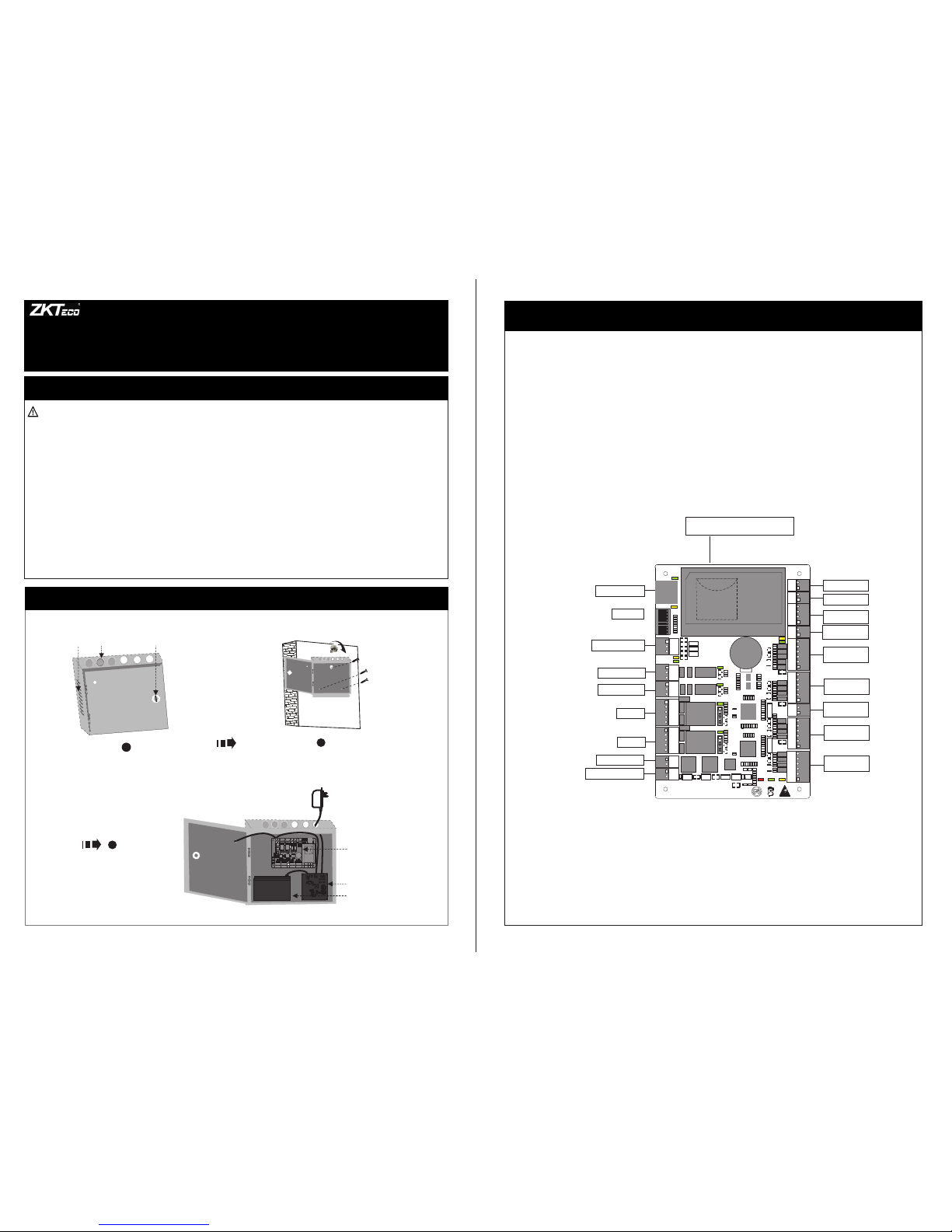
4.LED indicators, Wires, Auxiliary Input and Output
Notes:
1)Meaning of LED indicators:
LINK indicator(green): always(green) indicates TCP/IP
ACT indicator(yellow): flashing indicates data is in transmitting
TX indicator(yellow): flashing indicates it is sending data through
RX indicator(green): flashing indicates it is receiving data through
Auxiliary output indicator(green):always(green) indicates it is in use.
Lock indicator(green):always(green) indicates lock is open.
POWER indicator(red): always(red) indicates control panel power is on.
RUN indicator(green): flashing indicates the system works normally.
CARD indicator(yellow): flashing indicates card is punched on reader.
A Use 2-conducotor power cord
2)Recommended use of wires:
3)The auxiliary input may be connnected to infrared body detectors,
4)The auxiliary output may be connected to door bells,alarms,etc.
B Use 6-conductor wire between wiegand reader and control panel
C Use 4-conducotor lock power cord (RVV 4*0.75mm)
D Use 2-conducotor switch power cord(RVV 2*0.5mm)
communication is proper;
alam switches,etc.
through TCP/IP communication.
RS485 communication.
RS485 communication.
(RVVP 6*0.5mm) (Choose the appropriate cord for the interface
you connect, such as 6,8,10 cord.)
C3-200 Installation Instructions and Connection Guide
Version:1.2
Date: Jan. 2014
1.Cautions
1
2
3
Plea se note t he foll owing c autio ns. Mis -oper ation m ay lead t o perso nal inj ury or
equi pment f ailur e:
1)Do not e nergi ze the sy stem be fore in stall ation i s compl ete; ne ver car ry out
inst allat ion act iviti es when t he syst em is ene rgize d.
2)All pe riphe ral dev ices mu st be gro unded .
3)The co nduit s of wire s under r elay mu st be mat ched wi th meta led con duits , other
wire s can use P VC cond uits.
4)It is st rongl y recom mende d that th e lengt h of expo sed par t of any co nnect ion cab le
shou ld not be l onger t han 4 mm. P rofes siona l clamp ing too ls may be u sed to av oid
unin tenti onal co ntact o f expos ed wire s to avoi d short -circ uit or co mmuni catio n failu re.
5)It is re comme nded th at card r eader s and but tons be i nstal led at he ight of 1 .4m-1 .5m
abov e groun d.
6)It is re comme nded to u se the po wer sup ply for c ontro l panel , and ext ernal p ower
supp ly for ea ch lock .
7)The ap plian ce shal l be inst alled a nd wire d in acco rdanc e with na tiona l elect rical
code a nd by qua lifie d perso nnel on ly.
Desc ripti on of nor mal wor king st ate:
Conn ect the s ystem t o the pow er supp ly. If the s ystem w orks pr operl y, the POW ER
indi cator ( red) is l it cons tantl y and the R UN indi cator ( green ) flash es.
Valve re gulat ed lead -acid b atter y:
Cons tant vo ltage c harge v oltag e regul ation
Cycl e use : 14. 5V~14 .9V(2 5)
Init ial cur rent: l ess tha n 2.88A
Stan dby use : 13.6V ~13.8 V(25)
Capa city: 1 2V, 7.2Ah /20hr,
Batt ery Type: L C-RA1 27R2T 1
Caut ion:
Do not c harge i n a gas tig ht cont ainer.
Do not s hort th e batte ry term inals .
Do not i ncine rate
Flus h with wa ter at on ce if con tact is m ade wit h
elec troly te (Aci d)
Do not a ttemp t to disa ssemb le the ba ttery.
Get through the thread hole Fixed case
Control panel
The charging
circuit board
Backup battery
Heat
dissipation
hole Thread hole Key hole
Wiring the Control Panel, The Charging
Circuit Board and Backup Battery
PO
W
E
R
2.Fixed and Installation
GND
IN
BUTTON2
GND
GND
+12V
+12V
WD1
WD1
WD0
WD0
READER3
GLED
GLED
BEEP
BEEP
GND
+12V
WD1
WD0
READER2
GLED
BEEP
AUX1
AUX2
EXT
BUTTON1
READER1
+12V
GND
WD1
WD0
GLED
BEEP
+12V
GND
485485+
GND
GND
IN
IN
IN
GND
TX
RX
ACT
LINK
POWER
CARD
RUN
LAN
1
1
TX
RX
V+
POWER
PC
NCNCCOM
COMNONO
COM
COMNONONCNC
LOCK1 LOCK2
GND
GND
SEN
SEN
V-
GND
485-
485+
AUXOUT1AUXOUT2
LOCK
GND
+12V
1 2 3 4
ON
5 6 7 8
SD card
Advanced Access Control
READER4
GND
IN
BUTTON2
GND
GND
WD1
WD1
WD0
WD0
READER3
GLED
GLED
BEEP
BEEP
GND
WD1
WD0
READER2
GLED
BEEP
AUX1
AUX2
EXT
BUTTON1
READER1
GND
WD1
WD0
GLED
BEEP
GND
GND
GND
IN
IN
IN
GND
TX
RX
ACT
LINK
POWER
CARD
RUN
LAN
1
1
TX
RX
POWER
PC
NC
NC
COM
COM
NO
NO
COM
COM
NO
NO
NC
NC
LOCK1 LOCK2
GND
GND
SEN
SEN
GND
AUXOUT1 AUXOUT2
LOCK
GND
SD card
Advanced Access Control
READER4
V+
V-
+12V
LAN
485+
485-
+12V
+12V
+12V
+12V
485+
485-
+12V
ON
1
4
6
2
3
5
7
8
A
A
C
C
D
D
D
D
D
B
B
D
B
B
PC RS485 interface
Ethernet interface
Dip switch
Auxiliary output1
Auxiliary output2
Lock 1
Lock 2
Power of lock
Power of control panel
Auxiliary input1
Auxiliary input2
Extended
RS485 output
1# Door Button
1# Door
W iegand reader
1# Door
W iegand reader
2# Door Button
2# Door
W
iegand reader
2# Door
W
iegand reader
Note:
AUX In put (1- 2) conn ect to th e
infr ared hu man bod y induc tion,
wire less ex it butt on, win dows
sens or with d ry cont act (no
volt age);
Note:
AUX In put (1- 2) conn ect way i s
same
Note:
Outp ut Elec trica l
Para meter s:
Rate d Voltag e:
12V( DC)
Rate d Curre nt:
0.5A
Note :
1、Door b utton ( 1-2) co nnect t o Exit
butt on with d ry cont act.( no volt age);
2、Wieg and Rea der (1- 4) conn ect to
WG Rea der;
Port ( +12V) Outpu t Elect rical
Para meter s:
Rate d Voltag e: 12V( DC)
Rate d Curre nt: 0.5 A
Port ( BEEP GL ED) Out put Ele ctric al
Para meter s:
Rate d Voltag e: 5V(D C)
Rage d Curre nt: 0.5 mA
Note :
AUX Ou tput (1 -2)
conn ect to al arm, do or
bell a nd so on;
Port ( NO,CO M,NC)
Elec trica l Param eters :
MAX Vol tage:
36V( DC)
MAX Cu rrent : 1.25A
Note :
AUX Ou tput (1 -2)
conn ect way i s same
SD Car d Inter face;
Func tion: B ackup Ac cess Co ntrol L ogs
Note:
Lock P ower In put
Elec trica l Param eters :
Rate d Voltag e: 36V( DC)
Rate d Curre nt: 2A
Devi ce Powe r Input
Elec trica l Param eters :
Rate d Voltag e: 12V( DC)
Rate d Curre nt: 2A
Note :
Lock (1-2) :
Port ( SEN)c onnec t to door s ensor s ingle w ith
dry co ntact ( no volt age);
Port ( NO, COM , NC) Ele ctric al Para meter s:
MAX Vol tage: 3 6V(DC )
MAX Cu rrent : 2A
Note :
When y ou sele ct Wet mo de, The p ower is L ock
powe r, Lock (1 -2) tot al load d on’t mo re than
Lock p ower Ra ted cur rent (2 A)
Note :
Lock ( 1-2) co nnect w ay is sam e
1 2 3 4
ON
5 6 7 8
1
2
4
8
16
32
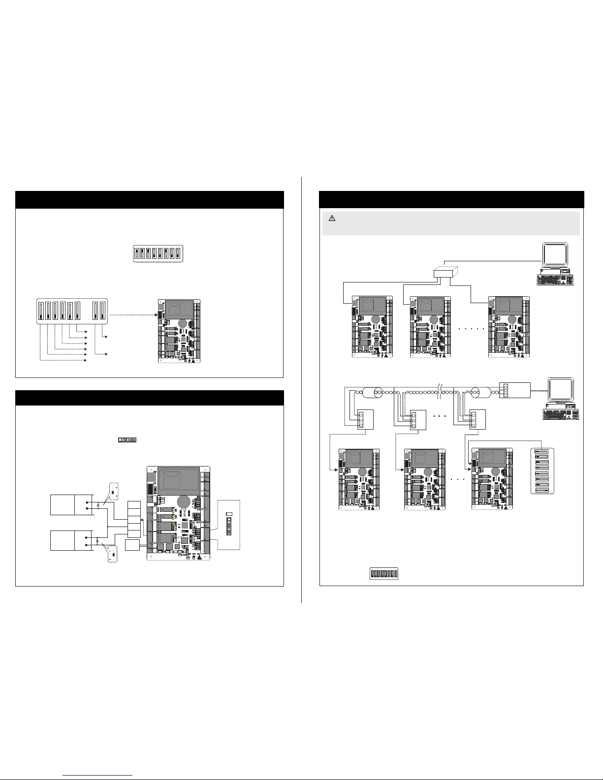
7.Equipment Communication
5、门锁连接
+
+
+
-
-
NC
NO
GND
COM
SEN
+
+
-
-
FR107
FR107
6.Connection Of Lock
-
PC
PC
LED
1
2
3
4
5
1 2 3 4
5 6 7 8
485+
485-
GND
485+
485+
485+
485-
485-
485-
GND
GND
GND
ON
1
2
3
4
5
5.RS485 Address Setting, Restore Factory Setting, Terminal Resistance Setting
1 2 3 4
ON
5 6 7 8
Loca tion of D IP switc h
Set RS 485 add ress th rough D IP swit ch:
1) Pla ce 1-6 on D IP swit ch are for s ettin g the num ber of co ntrol p anels w hen com munic ating t hroug h RS485 , it is ado pted fo r binar y codin g,
and li ttle en dian, t he addr ess rep resen ted by pl ace 1-6 a re show n as figu rue(5 -1).
2) Bef ore set ting th e addre ss, ple ase kee p the sys tem pow er off, J ump pla ce 1-6 to d esire d statu s. The add ress nu mber ca nnot be t he same a s
anot her one i n the net work. F or exam ple: to s et the de vice nu mber as 3 9 (39=1 +2+4+ 32), th e corre spond ing RS4 85 code i s 111001 ,
then J ump pla ce 1,2, 3 and 6 at “O N” stat us.
3) Pla ce 7 is for r estor ing fac tory de fault s ettin gs. Jum p it for th ree tim es with in 10 sec onds an d resta rt the sy stem. Al l infor matio n in
cont rol pan el will b e clear ed and th e syste m resto res fac tory de fault s ettin gs.RAM
4) Pla ce 8 is for s ettin g termi nal res istan ce when c ommun icati ng thro ugh RS4 85. Jum p it at “ON ” statu s, then i t is equi valen t to havi ng
a term inal re sista nce of 12 0 ohm bet ween 48 5+ and 48 5-.
Fig ure( 5- 1 )
Rest ore fac tory se tting
RS48 5 termi nal res istan ce
3) Whe n the Ele ctric al Lock i s conne cted to t he Acces s Contr ol Syst em, you n eed to pa ralle l one FR1 07
diod e (equi pped in t he pack age) to
prev ent the s elf-i nduct ance EM F affec ting th e syste m, do not r evers e the pol ariti es.
1) Con trol pa nel pro vides l ock con trol ou tput in terfa ces. Fo r NO lock , it is ope n when po wer is on , and clo sed whe n power i s off, so C OM and
NO int erfac es shou ld be use d; For NC l ock, it i s open wh en powe r is off, a nd clos ed when p ower is o n, so COM a nd NC int erfac es shou ld be
used .
2) Co ntr ol pan el sup por ts “dr y mod e” and “ wet m ode” b y sett ing t he jum per, i t is “w et mod e” whe n con nect ing “ V+ V-” In put in terf ace s to
sup ply p ower f or loc ks, p leas e sho rten 2 -3 an d 4-5 . Eq uipm ent f acto ry de faul t set ting i s dry mo de. F or set tin g “dry m ode ” and
ple ase r efer t o <<C3 -10 0/20 0/4 00 acc ess c ontr ol pan el in stal lat ion in str ucti ons> >.“we t mod e”,
NO Lock
LOCK
LOCK
“Wet mode” wiring diagram of lock connecting with external power supply.
Enlar ged dia gram
of lock p orts
NC Lock
Lock p ower
inpu t
Diode
Diode
Jump er
term inal
1.TCP/IP Communication
2.RS485 Communication
The backgro und PC software is a ble to communicat e with the system ac cording to two prot ocols(RS485 an d TCP/IP) for data exc hange and
remote management. The communication cable should be as far away from high-voltage lines as possible. Do not keep the communication cable
in parallel with power cords or bind them together.
Swit ch
n# con trol pa nel
seri al line
1# con trol pa nel
2# con trol pa nel
48 5
Conv erter
DIP sw itch
8# con trol pa nel
2# con trol pa nel
1# con trol pa nel
1) Internationally accepted RVSP(shielded twisted-pair) wire s should be used for communication to effectively avoid interference. RS4 85
of bus cascade connection. communication wires should be connected by means
3) One RS485 BUS may hold 63 control panel , but it is not recommended to connect with more than 32 units .units access control panels.
1 2 3 4 5 6 7 8
ON
Not es:
4) To enha nce the s tabil ity of co mmuni catio n it is ne cessa ry to kee p place 8 o f DIP when t he bus is l onger t han 300 m, swit ches of
2) Con sider ing sta bility o f commu nicat ion, it i s recom mende d the len gth of RS 485 bus i s less th an 600m
is pla ced at "O N " stat us.
the f irst a nd the l ast co ntro l pane l at “ON ” stat us. As sh own in t he fig ure ab ove, p lace 8 o f the DI P switc hes of u nits 1 # and 8#
GND
IN
BUTTON2
GND
GND
+12V
+12V
WD1
WD1
WD0
WD0
READER3
GLED
GLED
BEEP
BEEP
GND
+12V
WD1
WD0
READER2
GLED
BEEP
AUX1
AUX2
EXT
BUTTON1
READER1
+12V
GND
WD1
WD0
GLED
BEEP
+12V
GND
485485+
GND
GND
IN
IN
IN
GND
TX
RX
ACT
LINK
POWER
CARD
RUN
LAN
1
1
TX
RX
V+
POWER
PC
NC
NC
COM
COM
NO
NO
COM
COM
NO
NO
NC
NC
LOCK1 LOCK2
GND
GND
SEN
SEN
V-
GND
485-
485+
AUXOUT1 AUXOUT2
LOCK
GND
+12V
1 2 3 4
ON
5 6 7 8
SD card
Advanced Access Control
READER4
GND
IN
BUTTON2
GND
GND
+12V
+12V
WD1
WD1
WD0
WD0
READER3
GLED
GLED
BEEP
BEEP
GND
+12V
WD1
WD0
READER2
GLED
BEEP
AUX1
AUX2
EXT
BUTTON1
READER1
+12V
GND
WD1
WD0
GLED
BEEP
+12V
GND
485485+
GND
GND
IN
IN
IN
GND
TX
RX
ACT
LINK
POWER
CARD
RUN
LAN
1
1
TX
RX
V+
POWER
PC
NC
NC
COM
COM
NO
NO
COM
COM
NO
NO
NC
NC
LOCK1 LOCK2
GND
GND
SEN
SEN
V-
GND
485-
485+
AUXOUT1 AUXOUT2
LOCK
GND
+12V
1 2 3 4
ON
5 6 7 8
SD card
Advanced Access Control
READER4
 Loading...