

ZKTeco C3-100, C3-200, C3-400 User Manual

Control Panel User Manual
Version: 1.2
Date: Jan., 2014
About This Manual
This manual introduces C3-100/200/400 access control panel installation connection
and user manual.

Contents
i
Contents
1 Important Security Instructions...................................................................... - 1 -
1.1 Important Security Instructions................................................................- 1 -
1.2 Installation Cautions........................................................................ ........- 3 -
2 Introduction ......................................................................................................- 5 -
2.1 System Function Parameters....................................................................- 5 -
2.2 Product Technical Parameters..................................................................- 5 -
2.3 Control Operator Panel Indicators...........................................................- 7 -
3 Connection and Installation............................................................................. - 8 -
3.1 Case Installation ......................................................................................- 8 -
3.2 Installation of Access Control Operator Panel Wires...............................- 9 -
3.3 Control Operator Panel System Installation....................... ....................- 10 -
3.4 Control Operator Panel Connection Terminals......................................- 12 -
3.5 Connection with Door Sensors, Exit Switches, and Auxiliary Input Devices15 -
3.6 Connection with Wiegand Readers........................................................- 18 -
3.7 Relay Output Connection ......................................................................- 20 -
3.8 Access Control Operator Panel System Power Supply Structure...........- 25 -
4 Access Control Operator Panel System Networking....................................- 27 -
4.1 Access Control Networking Wires and Wiring..................... .................- 27 -
4.2 TCP/IP Network Communication..........................................................- 29 -
4.3 RS485 Network Communication...........................................................- 29 -
4.4 DIP Switch Setting (485 Address Setting, Factory Setting, and Terminal
Resistance Setting) ......................................................................................- 31 -

Important Security Instructions
- 1 -
1 Important Security Instructions
1.1 Important Security Instructions
1. Read, follow and keep instructions: Before operating the equipment, read and
follow strictly all security and operation instructions. Please keep the
instructions in good condition for future reference.
2. Accessories: Please use the accessories recommended by the manufacturer or
delivered with the product. Any other related product is not recommended as
the major alarming or monitoring system. The major a larming or monitoring
system should comply with the local applicable fire-prevention and security
standards.
3. Installation cautions: Do not place this equipment on any unstable table, tripod
mount, support or base, lest the equipment should fall and get damaged, and
more undesirably cause severe personal injuries.Therefore, it is important to
install the equipment as instructed by the manufacturer.
4. All peripheral devices must be grounded.
5. No external connection wires can be exposed. All connections and idle wire
ends must be wrapped with insulating tapes to prevent accidental contact with
exposed wires from damaging the equipment.
6. Repair: Do not attempt unauthorized repair of the equipment. Disassembly or
detachment is likely to cause shock or other risks. All repair jobs should be
done by qualified repair personnel.
7. Damages in need of repair: In any of the following cases, first disconnect the
AC/DC power supply from the equipment and notify qualified repair
personnel for repairs:
The power cord or connector is damaged.
There is entry of liquid or any other foreign object into the equipment.
The equipment is wetted or exposed to bad weather (rain, snow, etc.).

Control Panel User Manual
- 2 -
If the equipment cannot work normally even though operated as
instructed, please be sure to adjust only the control components specified
in the operation instructions. Incorrect adjustment of other control
components may cause damage to the equipment, and add to
troubleshooting workload of the qualified technicians.
The equipment falls down or its performance changes obviously.
8. Replacing components: If it is necessary to replace a component, the repair
personnel must use only the substitutes specified by the manufacturer.
9. Security inspection: After the equipment is repaired, the repair personnel are
supposed to conduct security inspection to ensure the equipment can work
normally.
10. Power supply: Operate the equipment with only the type of power supply
indicated on the label. Contact the operator for any uncertainty about the type
of power supply.
Violation of any of the following cautions is likely to lead to
personal injury or equipment failure, and any resulting damage will
not be covered by our routine maintenance.
Before installation, switch off the external circuit (that supplies
power to the system), including locks.
Before connecting the equipment to power supply, ensure the
output voltage is within the specified range.
Never connect
p
ower before completion of installation.

Important Security Instructions
- 3 -
1.2 Installation Cautions
1. The conduits of wires under relay must be matched with metaled conduits, other
wires can use PVC conduits, to prevent failure caused by rodent damage. Although a
control panel is designed with good antistatic, lightning-proof, and
leakage-proof functions, ensure its chassis and the AC ground wire are
connected properly and the AC ground wire is grounded physically.
2. It is recommended not to plug/unplug connection terminals frequently when
the system is energized. Be sure to unplug the connection terminals before
starting any relevant welding job.
3. Do not detach or replace any control panel chip without permission, because
unprofessional operation may cause damage to the control panel.
4. It is recommended not to connect any other auxiliary devices without
permission. All non-routine operations must be communicated to our
engineers in advance.
5. A control panel should not share one power socket with any other
large-current device.
6. It is preferable to install card readers and buttons at heights of 1.4-1.5m above
the ground, but the heights are subject to proper adjustment according to
customers’ usual practice.
7. It is advised to install control panels at places easy of maintenance, like a
weak electric well.
8. It is strongly recommended that the exposed part of any connection terminal
should not be longer than 4mm, and specialized clamping tools may be used
to avoid short-circuit or communication failure resulting from accidental
contact with excessive exposed wires.
9. To save access control event records, read data periodically from control
panels.

Control Panel User Manual
- 4 -
10. Get prepared countermeasures according to application scenarios for
unexpected power failure, like selecting power supply with UPS.
11. The connection between a card reader and a control panel should not be
longer than 100m.
12. The connection between a PC and a control panel should be shorter than
1200m for RS485 communications. A length within 600m is recommended to
make communications more stable.
13. To protect the access control system against the self-induced electromotive
force generated by an electronic lock at the instant of switching off/on, it is
necessary to connect a diode in parallel (please us e th e FR107 deli vere d wit h
the system) with the electronic lock to release the self-induced electromotive
force during onsite connection for application of the access control system.
14. It is recommended that an electronic lock and a control panel should use
respective power supplies.
15. It is recommended to use the power supply delivered with the system as the
control panel power supply.
16. In a place with strong magnetic interference, galvanized steel pipes or shielded
cables are recommended, and proper grounding is required.
17. The appliance shall be installed and wired in accordance with national
electrical code and by qualified personnel only.

Introduction
- 5 -
2 Introduction
The access control management s ystem is a new modernized security management
system, which is an effective measure for security and protection management. It is
mainly used to manage entrances and exits of important places, such as banks, hotels,
equipment rooms, offices, smart communities, and factories.
2.1 System Function Parameters
High-speed 32-bit 400MHz CPU, 32M RAM, and 256M Flash.
Embedded LINUX operating system.
One-door/two-door two-way access or four-door one-way access.
A maximum of 30,000 card holders and 100,000 offline event records.
Support of multiple Wiegand card formats and a passwor d keypad, compatible
with various types of cards.
Use of dual communication technologies: the Ethernet plus the RS485
industrial bus, for reliable communications.
With a watchdog (hardware) built in the control panel to prevent crash.
Over-current, over-voltage, and inverse-voltage pr otection for input of power
supply to the control panel.
Over-current protection for the power supply to card readers.
Instant over-voltage protection for all input/output ports.
Instant over-voltage protection for communication ports.
2.2 Product Technical Parameters
Working power supply: Rated voltage 12V (±20%) DC; Rated current 2A.
Working environment: Tempe ra t ure 0° C- 55°C; humidity 10%-80%.
Electronic lock relay output: The maximum switching voltage: 36V(DC); The
maximum switching current: 2A

Control Panel User Manual
- 6 -
Auxiliary relay output: The maximum switching voltage: 36V(DC); The
maximum switching current: 1.25A
With detachable connection terminals made of alloy-steel non-magnetic flange
materials.
Outline dimensions of the control PCB: 160mm (length) × 106mm (width) for
C3-100/200; 216mm (length) × 106mm (width) for C3-400.
External box dimensions: 360mm × 285mm × 75mm.
Valve regulated lead-acid battery:
Constant voltage charge voltage regulation
Cycle use : 14.5V~14.9V(25)
Initial current: less than 2.88A
Standby use: 13.6V~13.8V(25)
Capacity: 12V, 7.2Ah/20hr,
Battery Type: LC-RA127R2T1
Battery Caution:
Do not charge in a gas tight container.
Do not short the battery terminals.
Do not incinera te
Flush with water at once if contact is made with electrolyte (Acid)
Do not attempt to disassemble the battery.
Introduction
- 7 -
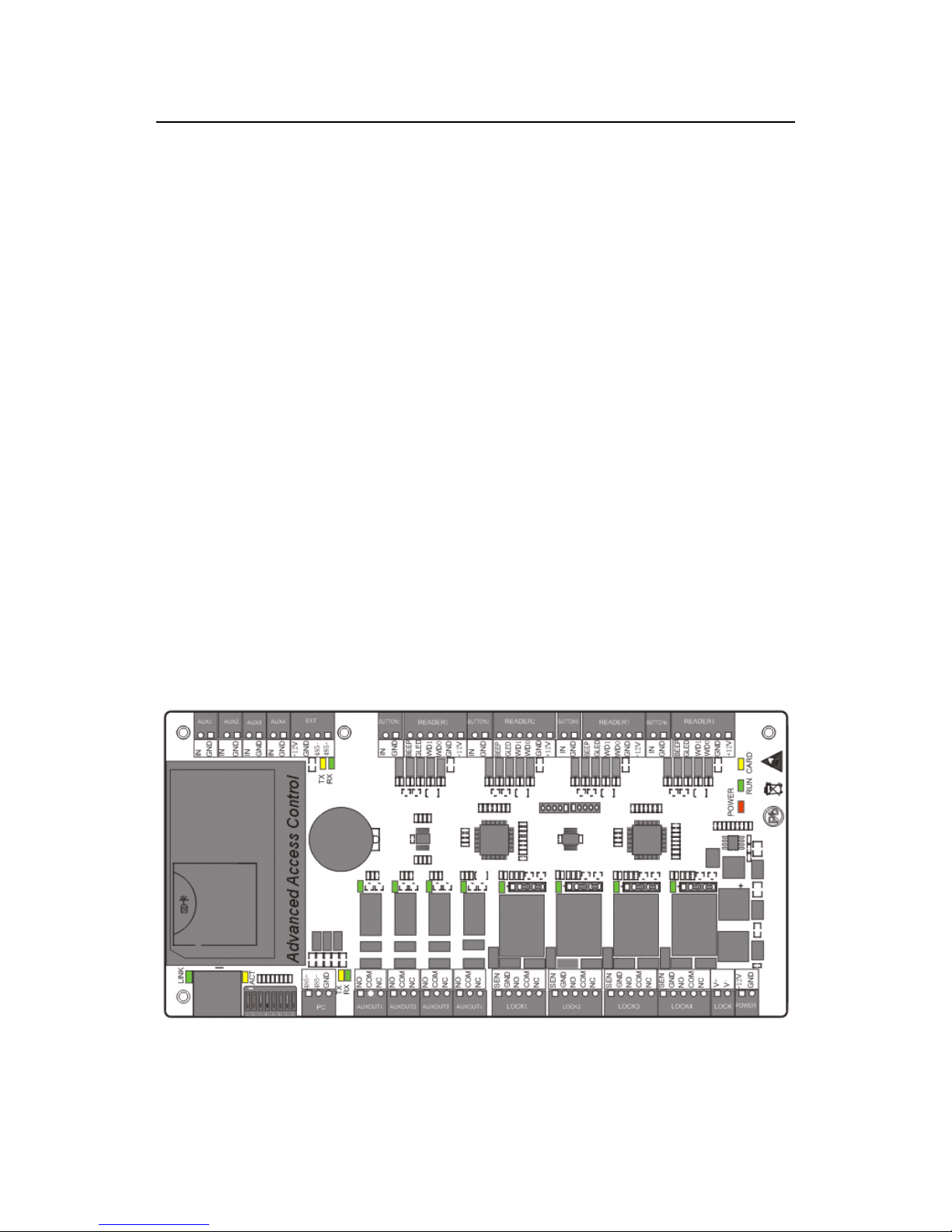
2.3 Control Operator Panel Indicators
When the C3-100/200/400 is powered on, normally the POWER indicator (red) is lit
constantly, the RUN indicator (green) flashes (indicating the system is normal), and
other indicators are all off.
Except the cases as follows:
1. LINK indicator (green): indicates proper TCP/IP connection if it is lit
constantly;
2. ACT indicator (yellow): indicates transmission of TCP/IP data if it flashes;
3. TX indicator (yellow): indicates sending of 485 data if it flashes;
4. RX indicator (green): indicates receiving of 485 data if it flashes;
5. Lock indicator (green): indicates unlocking if it is lit constantly (if the
auxiliary output indicator is lit in green constantly, it indicates the auxiliary
device is enabled);
6. CARD indicator (yellow): indicates input of Wiegand signal if it is lit.
See the indicators in the following figure:
Figure 2-1 Indicators in the C3-400
Control Panel User Manual
- 8 -
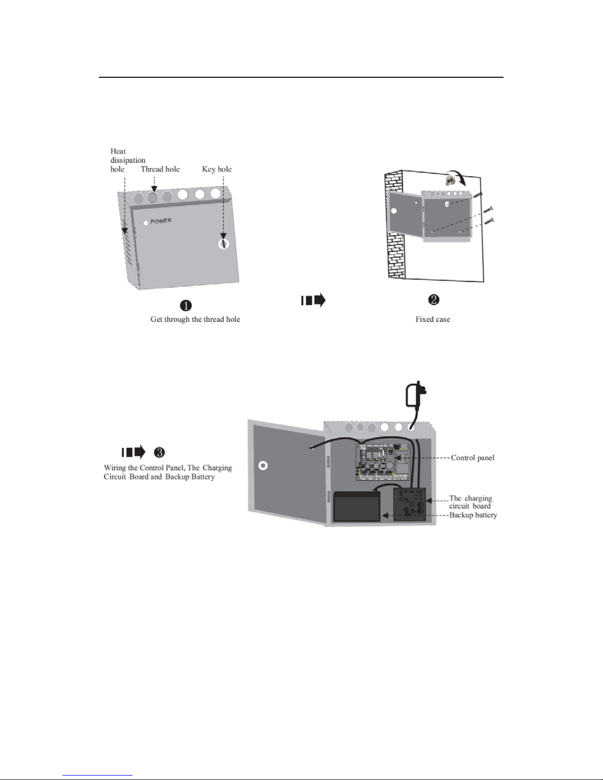
3 Connection and Installation
3.1 Case Installation
Connection and Installation
- 9 -
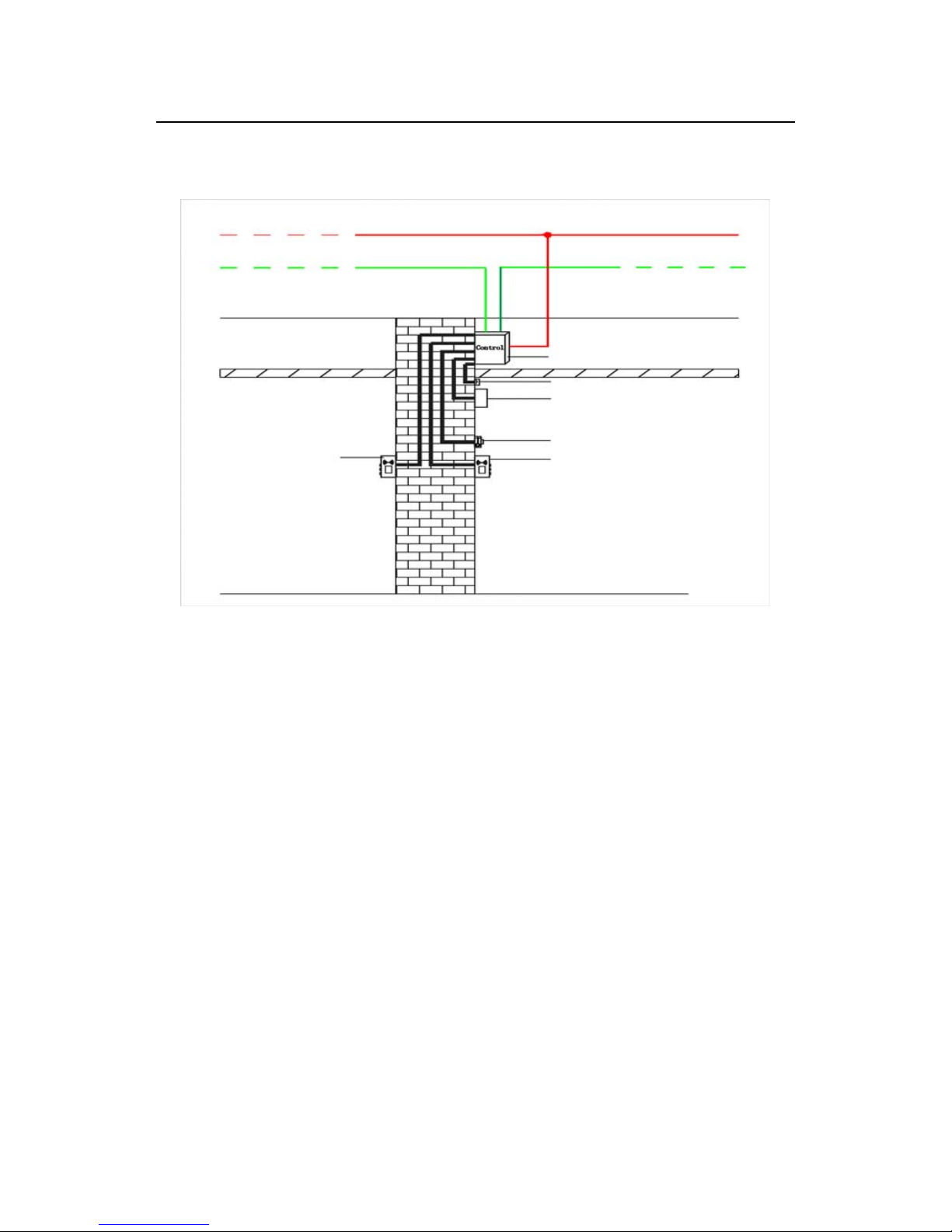
3.2 Installation of Access Control Operator Panel
Wires
220V input
TCP/IP network communication wire
RS485 network
communication wire
C3 access control
operator panel
Ceiling
Door sensor
Electronic lock
Exit button
Outdoor Wiegand
card reader
Indoor Wiegand card reader
Outdoor
Indoor
Figure 3-1 Access Control Operator Panel Wire Installation Diagram
Notes:
1. Before connection, make sure the power supply is disconnected, because
connection with power connected will cause severe damage to the equipment.
2. The access control wires must be separated according to heavy and light
current; the control panel wires, electronic lock wires, and exit button wires
must run through their respective casing pipes.
 Loading...