

ZKTeco Atlas x60 Installation Manual

Installation Guide
Atlas x60 Series
Access Control Panels

2
What’s in the Box
NC
RUN
PWR
GND
COMM
+12V
GND
PWR
485B
485A
+12V
RUN
GND
D0
D1
RETURN
HOLD
SHIELD
RETURN
GLED
HOLD
SHIELD
COMM1
GLED
RLED
BEEP
COMM2
+12V
WLAN
GND
D0
D1
DOOR
RLED
BEEP
NC
NO
SEN
BUT
GND
COM
NO
COM
485A
SEN
GND
4
5
3
6
2
7
1
8
0
9
F
A
E
B
D
C
485B
GNDNCCOMNOAUX1
NC
BUT
NC
NO
COM
NO
SEN
GND
SEN
BUT
GND
AUX2
BUT
GND
COM
+12V
GND
D0
D1
RETURN
GLED
RLED
BEEP
HOLD
SHIELD
+12V
GND
D0
D1
RETURN
GLED
RLED
BEEP
HOLD
SHIELD
BREAK
GND
AC FAIL
BAT FAIL
+12V
GND
4 Diodes4 Screws & Anchors 1 Screwdriver
Atlas x60 Series Access Control Panels Installation Guide

CONTENTS
What’s in the Box .......................................................................2
Optional Accessories ..............................................................4
Safety Precautions
Product PIN Diagram
LED Indicators ..............................................................................7
Product Dimension ..................................................................8
Installation of Panel & Cabinet .........................................9
Wiring Legend ..........................................................................10
Power Wiring Diagram ......................................................11
Wiegand Connection ..........................................................12
OSDP Connection ..................................................................13
FR1500A Connection ..........................................................14
DIP Switch Setting for FR1500A Device ID ..........15
REX Connections ....................................................................16
Lock Connection ....................................................................17
AUX. I/O Connection ...........................................................18
Ethernet Connection ..........................................................19
Typical Installation .................................................................20
Troubleshooting .....................................................................21
Reader 485 Setting Table ..................................................22
Electrical Specifications ....................................................24
Introduction ..............................................................................27
Understanding the Atlas Series Network ............28
Initial Controller Setup .......................................................29
Connect the Controller to the Network ...............35
Complete the Configuration ........................................36
Add a User and Test Access ...........................................40
Add Secondary Controllers ...........................................43
Mobile App ...................................................................................44
Special Considerations for Complex Networks
Where to Go Next .................................................................48
.....................................................................5
..............................................................6
.......48
3
Web Management Application
Programming Guide starts at
page 26
Atlas x60 Series Access Control Panels Installation Guide
4
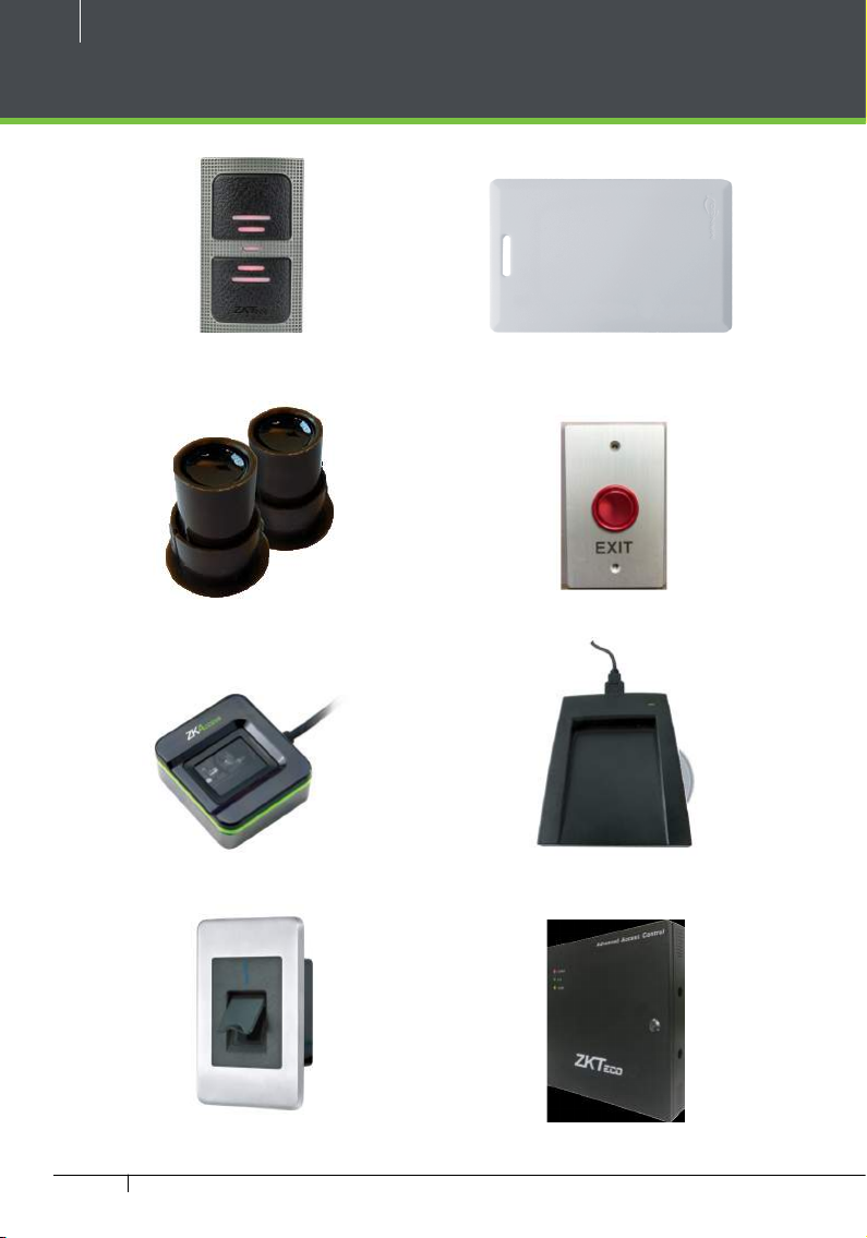
Optional Accessories
Wiegand Card Reader
Door Sensor
SLK20R Enrollment reader
Prox Card
Exit Button
CR10E Card Enrollment Reader
FR1500A FP & Prox Reader
Atlas x60 Series Access Control Panels Installation Guide
Atlas x60 Metal Cabinet
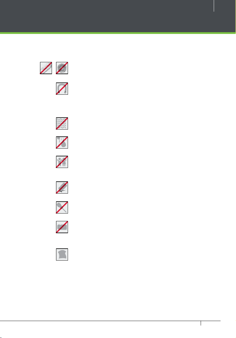
Safety Precautions
The following precautions are to keep user’s safe and prevent any damage.
Please read carefully before installation.
Do not expose to direct sunlight, water, dust and soot.
Do not place any magnetic objects near the product.
Magnetic objects such as magnets, CRT, T V, monitors or
speakers may damage the device
Do not place the device next to heating equipment.
Prevent water, drinks or chemicals leaking into the device.
This product is not intended for use by children unless they
are supervised.
5
Do not drop or damage the device.
Do not disassemble, repair or modify the device.
Do not use the device for any purpose other than those
specied.
Remove dust or dirt regularly. While cleaning, wipe dust o
with a smooth cloth or towel instead of water.
Contact your supplier in case of any problem!
Atlas x60 Series Access Control Panels Installation Guide
6
SHIELD
SHIELD
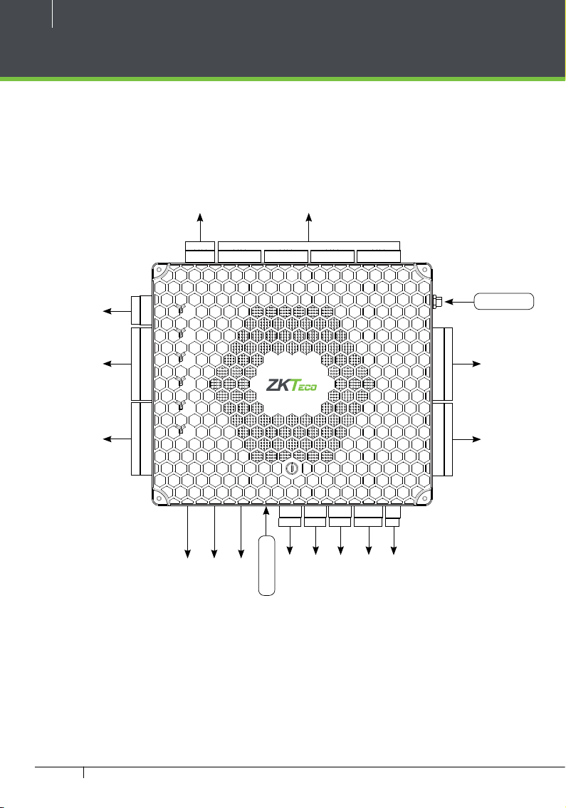
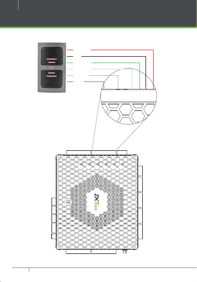
Product PIN Diagram
Status Indicator
4 Lock & Door Sensor
RS485 Reader
Wiegand
Reader 1
Wiegand
Reader 2
+12V
GND
485B
485A
+12V
GND
D0
D1
RETURN
GLED
RLED
BEEP
HOLD
+12V
GND
D0
D1
RETURN
GLED
RLED
BEEP
HOLD
(POE)
PWR
RUN
COMM1
COMM2
WLAN
DOOR
Ethernet Port
NC
RUN
PWR
GND
COMM
NC
NO
SEN
BUT
GND
COM
NC
NO
SEN
BUT
GND
COM
NC
NO
COM
NO
SEN
SEN
BUT
GND
BUT
GND
COM
WIFI
+12V
GND
D0
(not used)
D1
RETURN
GLED
RLED
BEEP
HOLD
SHIELD
+12V
GND
D0
D1
RETURN
GLED
RLED
4
5
3
6
2
7
1
8
0
9
F
A
E
B
D
C
485A
485B
GNDNCCOMNOAUX1
GND
AUX2
BREAK
GND
AC FAIL
BAT FAIL
+12V
RESET
Reader Ethernet Port
USB Port
(not used)
Aux Input
Aux Output
RS485 Communication
Power Detection
Atlas Power
BEEP
HOLD
SHIELD
GND
Wiegand
Reader 3
Wiegand
Reader 4
Figure 1
The function of reset button (once reset button is pressed, LED will blink fast):
1. Press reset button for about 2-5 seconds, zk firmware will check if there is a USB disk which stores an upgrade package
inserted into controller, if yes, then controller will do firmware upgrade automatically.
2. Press reset button for about 5-10 seconds, zk firmware will temporarily set IP to default 169.254.202.242.
Atlas x60 Series Access Control Panels Installation Guide
COMM
RUN
GND
PWR
NC
COM
NO
SEN
GND
BUT
NC
COM
NO
SEN
GND
BUT
NC
COM
NO
SEN
GND
NC
COM
NO
SEN
GND
BUT
PWR
RUN
COMM1
COMM
RUN
GND
PWR
NC
COM
NO
SEN
GND
BUT
NC
COM
NO
SEN
GND
BUT
NC
COM
NO
SEN
GND
NC
COM
NO
SEN
GND
BUT
PWR
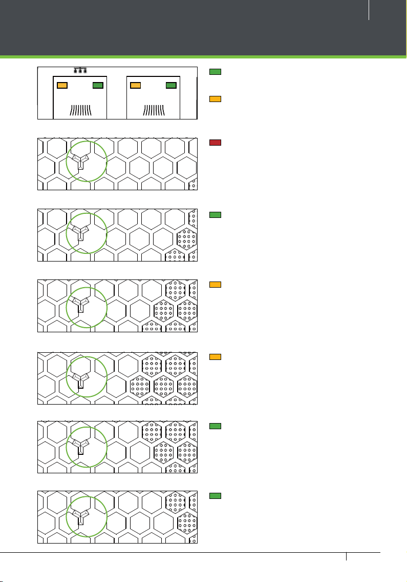
LED Indicators
COMM
RUN
GND
PWR
NC
COM
NO
SEN
GND
BUT
NC
COM
NO
SEN
GND
BUT
NC
COM
NO
SEN
GND
NC
COM
NO
SEN
GND
BUT
PWR
RUN
COMM
RUN
GND
PWR
NC
COM
NO
SEN
GND
BUT
NC
COM
NO
SEN
GND
BUT
NC
COM
NO
SEN
GND
NC
COM
NO
SEN
GND
BUT
PWR
RUN
COMM1
COMM2
WLAN
COMM
RUN
GND
PWR
NC
COM
NO
SEN
GND
BUT
NC
COM
NO
SEN
GND
BUT
NC
COM
NO
SEN
GND
NC
COM
NO
SEN
GND
BUT
PWR
RUN
COMM1
COMM2
COMM
RUN
GND
PWR
NC
COM
NO
SEN
GND
BUT
NC
COM
NO
SEN
GND
BUT
NC
COM
NO
SEN
GND
NC
COM
NO
SEN
GND
BUT
Figure 2
PWR
Figure 3
RUN
7
LINK Solid Green LED indicates TCP/IP
communication is normal
Flashing (ACT )Yellow LED indicates
data communication is in progress
Solid (POWER) Red LED indicates the
panel is powered on.
Flashing (RUN) Green LED indicates
that panel is in normal working state.
COMM1
COMM2
WLAN
DOOR
Figure 4
Figure 5
Figure 6
Figure 7
Figure 8
COMM1 Flashing Yellow indicates the
devices (for example, the PC).
system is communicating with upper-level
COMM2 Flashing Yellow indicates the
system is communicating with lower-level
devices (for example, readers).
Flashing (WLAN) Green LED indicates
the system is communicating in wireless
(Wi-Fi) mode.
Flashing (DOOR) Green LED indicates
a door opening signal (a door is opened).
Atlas x60 Series Access Control Panels Installation Guide
8
GND
COMM
GND
485B
485A
RETURN
GLED
RLED
BEEP
HOLD
SHIELD
+12V
GND
RETURN
GLED
RLED
BEEP
HOLD
SHIELD
485A
485B
GND
BREAK
GND
AC FAIL
BAT FAIL
+12V
GND
+12V
GND
D0
D1
RETURN
GLED
RLED
BEEP
HOLD
SHIELD
MM
RUN
GND
R
NC
COM
NO
SEN
GND
BUT
NC
COM
NO
SEN
GND
BUT
485A
485B
GNDNCCOMNOAUX1
GND
AUX2
BREAK
GND
A
BAT FAIL
+12V
GND
+12V
GND
D0
D1
RETURN
GLED
RLED
BEEP
HOLD
SHIELD
+12V
GND
D0
D1
RETURN
GLED
RLED
BEEP
HOLD
SHIELD
MM
RUN
GND
R
NC
COM
NO
SEN
GND
BUT
NC
COM
NO
SEN
GND
BUT
NC
COM
NO
SEN
GND
BUT
NC
COM
NO
SEN
GND
BUT
RETURN
SHIELD
RETURN
SHIELD
485A
485B
GNDNCCOMNOAUX1
GND
AUX2
BREAK
GND
A
BAT FAIL
+12V
GND
+12V
GND
D0
D1
RETURN
GLED
RLED
BEEP
HOLD
SHIELD
+12V
GND
D0
D1
RETURN
GLED
RLED
BEEP
HOLD
SHIELD
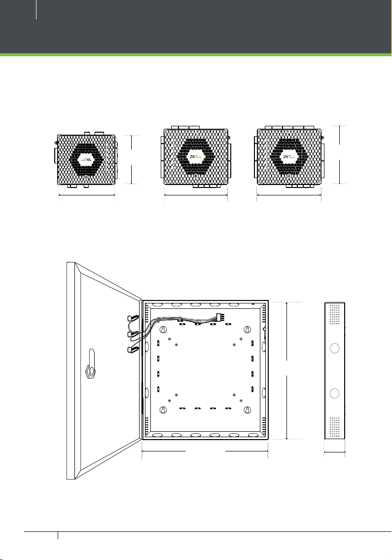
Product Dimension
Atlas-160 Atlas-260 Atlas-460
PW
NC
NO
SEN
BUT
GND
GND
COM
AUX1
AUX2
4
5
3
6
2
7
1
8
0
9
F
A
E
B
D
C
PWR
RUN
COMM1
COMM2
WLAN
DOOR
PWR
RUN
4.17in
(106mm)
D0
D1
CO
+12V
GND
PWR
485B
485A
+12V
RUN
GND
D0
D1
COMM1
RETURN
GLED
RLED
BEEP
COMM2
HOLD
SHIELD
+12V
WLAN
GND
D0
D1
DOOR
RETURN
GLED
RLED
BEEP
HOLD
SHIELD
4
5
3
6
2
7
1
8
0
9
F
A
E
B
D
C
C FAIL
PW
CO
+12V
GND
PWR
485B
485A
+12V
RUN
GND
D0
D1
COMM1
GLED
RLED
BEEP
COMM2
HOLD
+12V
WLAN
GND
D0
D1
DOOR
GLED
RLED
BEEP
HOLD
4
5
3
6
2
7
1
8
0
9
F
A
E
B
D
C
6.73in
(171mm)
C FAIL
7.75in (197mm)7.75in (197mm)6.3in (160mm)
Figure 9
Atlas x60 Metal Cabinet
11in
(280mm)
15in (380mm)
3.15in
(80mm)
Figure 10
Atlas x60 Series Access Control Panels Installation Guide
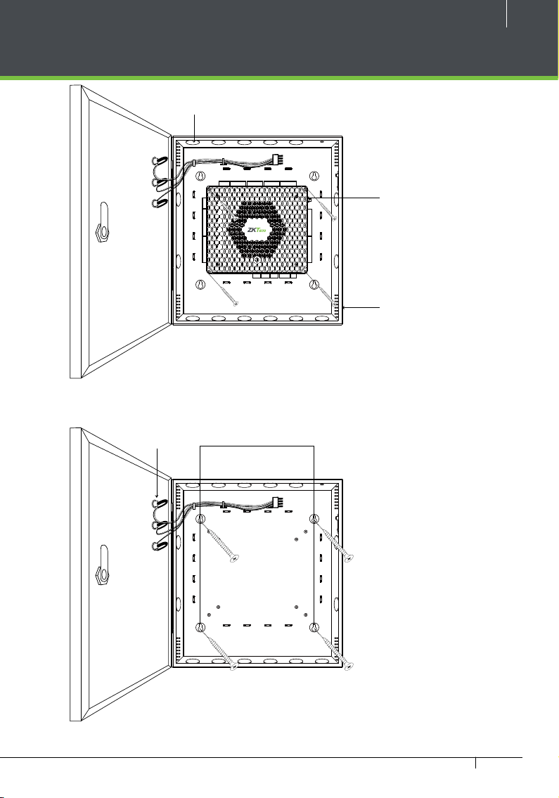
Installation of Panel & Cabinet
RETURN
SHIELD
RETURN
SHIELD
485A
485B
GNDNCCOMNOAUX1
GND
AUX2
BREAK
GND
A
BAT FAIL
+12V
GND
+12V
GND
D0
D1
RETURN
GLED
RLED
BEEP
HOLD
SHIELD
+12V
GND
D0
D1
RETURN
GLED
RLED
BEEP
HOLD
SHIELD
Cable Conduit
(Punch hole for cables)
9
Step 1
Pass the cable through holes
NC
NC
NC
NC
NO
NO
NO
SEN
SEN
SEN
BUT
BUT
RUN
PWR
GND
COM
COMM
+12V
GND
PWR
485B
485A
+12V
RUN
GND
D0
D1
COMM1
GLED
RLED
BEEP
COMM2
HOLD
+12V
WLAN
GND
D0
D1
DOOR
GLED
RLED
BEEP
HOLD
BUT
GND
GND
GND
COM
COM
COM
4
5
3
6
2
7
1
8
0
9
F
A
E
B
D
C
Figure 11
Step 2
Mount the Metal Cabinet
Mounting HolesState Indicators
NO
SEN
BUT
GND
Atlas x60 Panel
C FAIL
Heat Dissipation Grill
Step 3
Fasten the Panel with four screws.
Figure 12
We recommend drilling the mounting plate screws into solid wood (i.e. stud/beam). If a stud/beam cannot be
found, then use the supplied drywall plastic mollies (anchors).
Atlas x60 Series Access Control Panels Installation Guide
10
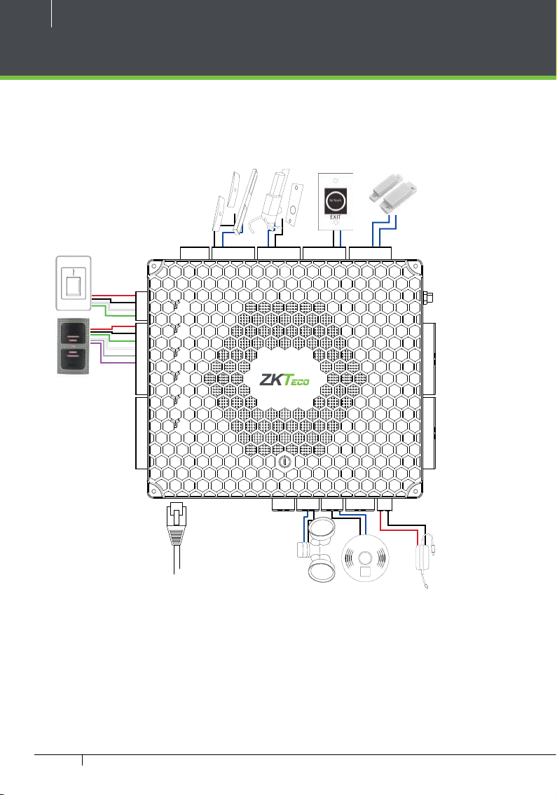
Wiring Legend
FR1500A/OSDP
Reader
+12V
GND
485B
485A
+12V
GND
D0
D1
RETURN
GLED
RLED
BEEP
HOLD
Card Reader
SHIELD
+12V
GND
D0
D1
RETURN
GLED
RLED
BEEP
HOLD
SHIELD
PWR
RUN
COMM1
COMM2
WLAN
DOOR
Door Sensor
Normally
SEN
BUT
GND
Open Lock
Normally
NC
NO
SEN
GND
COM
4
5
3
6
2
7
1
8
0
9
F
A
E
B
D
C
Close Lock
NC
NO
RUN
PWR
GND
COM
COMM
Exit Button
NC
BUT
NC
NO
COM
NO
SEN
SEN
BUT
GND
BUT
GND
COM
+12V
GND
D0
D1
RETURN
GLED
RLED
BEEP
HOLD
SHIELD
+12V
GND
D0
D1
RETURN
GLED
RLED
BEEP
HOLD
SHIELD
485A
485B
GNDNCCOMNOAUX1
GND
AUX2
BREAK
GND
AC FAIL
BAT FAIL
+12V
GND
P
Y
U
L
S
K
H
E
E
T
O
W
T
Ethernet Cable
POE
Floodlight
Detector
T
E
S
S
E
T
T
W
O
T
E
E
H
K
S
L
U
Y
P
ALARM
FIRE
12V DC
Power Supply
The auxiliary input may be connected to infrared motion sensors, fire alarms, or smoke detectors. The auxiliary
output may be connected to alarms, cameras or door bells, etc.
Figure 13
Atlas x60 Series Access Control Panels Installation Guide
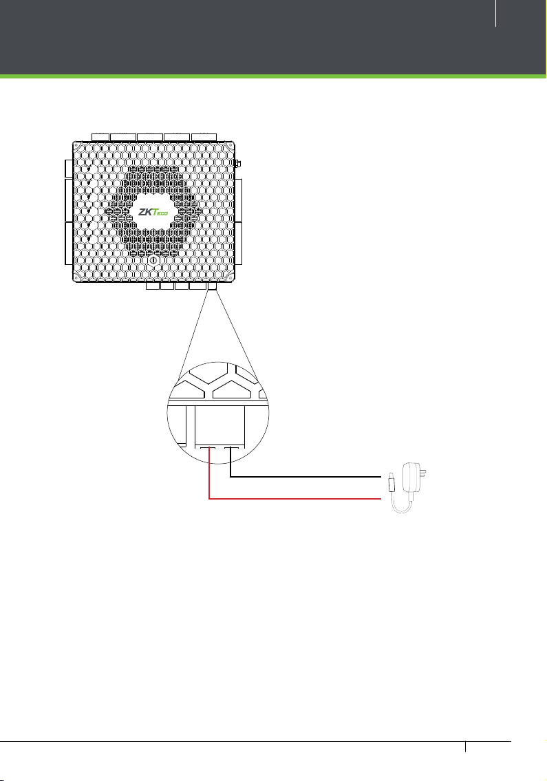
Power Wiring Diagram
RETURN
SHIELD
RETURN
SHIELD
+12V
GND
D0
D1
GLED
RLED
BEEP
HOLD
SHIELD
+12V
GND
D0
D1
GLED
RLED
BEEP
HOLD
SHIELD
BAT FAIL
+12V
GND
+12V
GND
D0
D1
RETURN
GLED
RLED
BEEP
HOLD
SHIELD
+12V
GND
D0
D1
RETURN
GLED
RLED
BEEP
HOLD
SHIELD
NC
NC
NO
NO
SEN
SEN
BUT
RUN
PWR
GND
GND
COM
COMM
+12V
GND
PWR
485B
485A
+12V
RUN
GND
D0
D1
COMM1
GLED
RLED
BEEP
COMM2
HOLD
+12V
WLAN
GND
D0
D1
DOOR
GLED
RLED
BEEP
HOLD
COM
4
3
2
1
0
F
E
D
485A
485B
BUT
GND
5
6
7
8
9
A
B
C
GNDNCCOMNOAUX1
NC
COM
NO
SEN
GND
GND
NC
BUT
COM
AUX2
BREAK
GND
AC FAIL
NO
SEN
BAT FAIL
BUT
GND
RETURN
RETURN
+12V
GND
11
Figure 14
12V DC
Atlas x60 Series Access Control Panels Installation Guide
12
+12V
GND
485B
485A
+12V
GND
D0
D1
RETURN
GLED
RLED
BEEP
Wiegand Connection
DC+(6-14V)
GND
Wiegand D0
Wiegand D1
Green LED
Beeper
Wiegand Card Reader
485A
485B
GND
NC
COM
NO
AUX1
GND
AUX2
BREAK
GND
AC FAIL
BAT FAIL
+12V
GND
Atlas x60 Series Access Control Panels Installation Guide
RETURN
DOOR
RETURN
D1
SHIELD
RETURN
HOLD
GND
D0
D1
WLAN
SHIELD
+12V
GND
D0
D0
D1
COMM1
COMM2
RETURN
HOLD
GLED
RLED
BEEP
D0
D1
GLED
+12V
RLED
BEEP
+12V
+12V
485A
485B
GND
GND
PWR
RUN
+12V
GND
COMM
RUN
GND
PWR
NC
COM
NO
SEN
GND
BUT
NC
COM
NO
SEN
GND
BUT
NC
COM
NO
SEN
GND
BUT
NC
COM
NO
SEN
GND
BUT
SHIELD
HOLD
GLED
RLED
BEEP
0
1
F
2
E
3
D
4
C
5
B
6
A
7
9
8
SHIELD
HOLD
GLED
RLED
BEEP
Figure 15
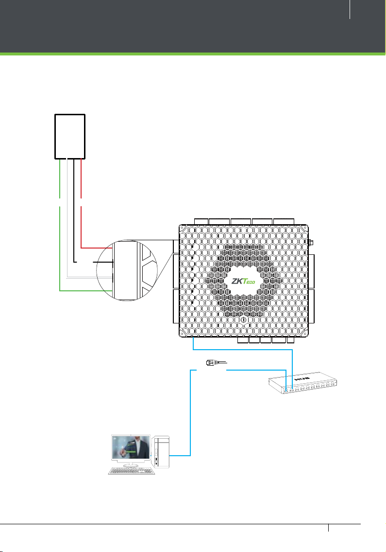
OSDP Connection
RETURN
SHIELD
RETURN
SHIELD
COMM
RUN
GND
PWR
NC
COM
NO
SEN
GND
BUT
NC
COM
NO
SEN
GND
BUT
NC
COM
NO
+12V
GND
485B
485A
PWR
NOTE: OSDP and ZKTeco RS485 (FR1500A readers) cannot both be connected to one control panel.
OSDP Reader
D0 D1
DC
NC
NC
NC
NO
NO
SEN
BUT
SEN
BUT
BUT
GND
COM
GND
COM
4
5
3
6
2
7
1
8
0
9
F
A
E
B
D
C
GND
NO
SEN
RUN
PWR
GND
GND
COM
COMM
+12V
GND
PWR
485B
485A
+12V
RUN
GND
D0
D1
COMM1
GLED
RLED
BEEP
COMM2
HOLD
+12V
WLAN
GND
D0
D1
DOOR
GLED
RLED
BEEP
HOLD
13
NC
NO
SEN
BUT
GND
COM
+12V
GND
D0
D1
RETURN
GLED
RLED
BEEP
HOLD
SHIELD
+12V
GND
D0
D1
RETURN
GLED
RLED
BEEP
HOLD
SHIELD
485A
485B
GNDNCCOMNOAUX1
GND
AUX2
BREAK
GND
AC FAIL
BAT FAIL
+12V
GND
ETHERNET
Figure 16
Atlas x60 Series Access Control Panels Installation Guide
14
COMM
RUN
GND
PWR
NC
COM
NO
SEN
GND
BUT
NC
COM
NO
SEN
GND
BUT
NC
COM
NO
+12V
GND
485B
485A
PWR
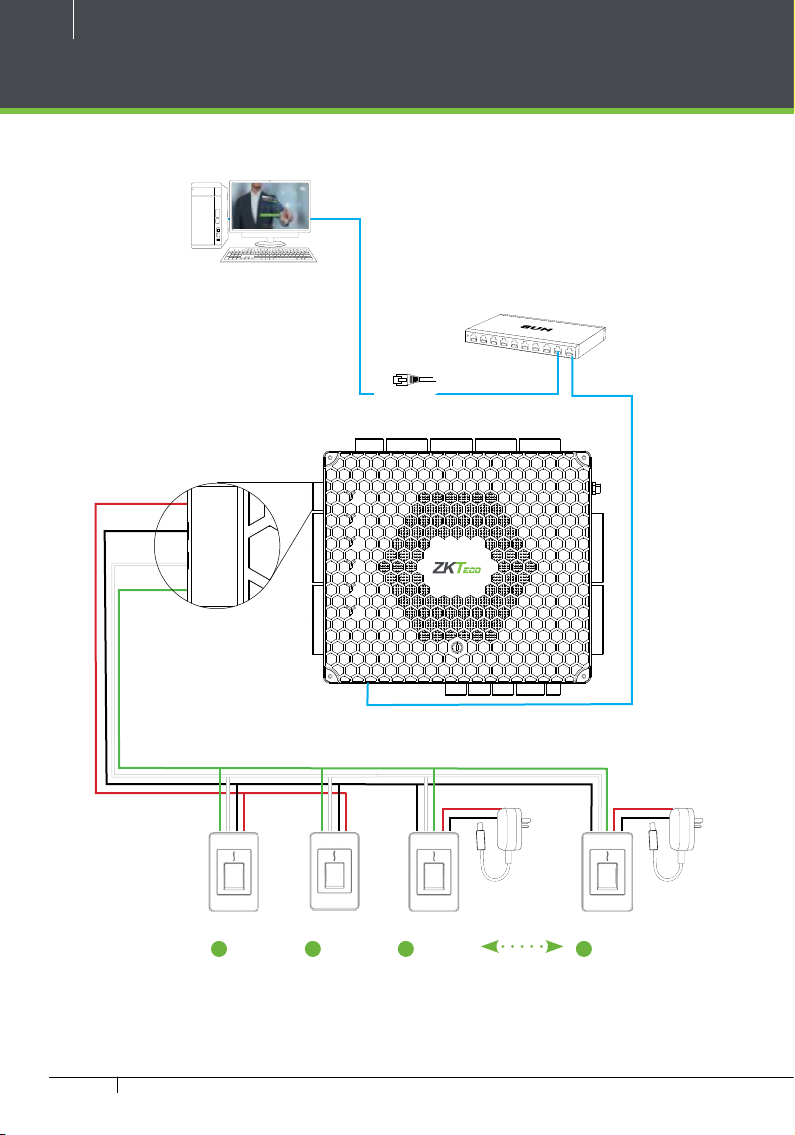
FR1500A Connection
+12V
GND
485B
485A
+12V
GND
RETURN
GLED
RLED
BEEP
HOLD
SHIELD
+12V
GND
RETURN
GLED
RLED
BEEP
HOLD
SHIELD
ETHERNET
NC
NC
NO
NO
SEN
SEN
BUT
RUN
PWR
GND
GND
COM
COMM
PWR
RUN
D0
D1
COMM1
COMM2
WLAN
D0
D1
DOOR
GND
COM
4
5
3
6
2
7
1
8
0
9
F
A
E
B
D
C
NC
NC
NO
NO
SEN
SEN
BUT
COM
BUT
BUT
GND
GND
COM
+12V
GND
D0
D1
RETURN
GLED
RLED
BEEP
HOLD
SHIELD
+12V
GND
D0
D1
RETURN
GLED
RLED
BEEP
HOLD
SHIELD
2
FR1500A
1
FR1500A
Atlas x60 Series Access Control Panels Installation Guide
3
FR1500A
Figure 17
485A
485B
GNDNCCOMNOAUX1
12V DC
GND
AUX2
BREAK
GND
AC FAIL
BAT FAIL
+12V
GND
12V DC
8
FR1500A
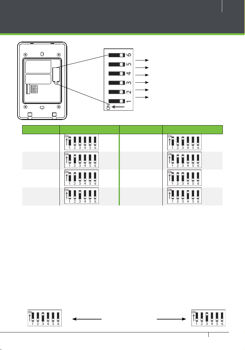
DIP Switch Setting for FR1500A Device ID
RS485 Terminal Resistance
8
4
2
1
DIP Switch
18
Figure
Address Switch Settings Address Switch Settings
1 5
2 6
3 7
15
4 8
Important Notes
1. There are six DIP switches on the
back of FR1500A, Switches 1-4 is for
RS485 address, switch 5 is reserved,
switch 6 is for reducing noise on long
RS485 cable.
2. Set the odd number for IN reader,
and the even number for OUT reader
(for eg. For two readers for one doorthe RS485 address 1 is for IN reader,
RS485 address 2 is for OUT reader)
Distance: More than 200 meters
3. If FR1500A is powered from Atlas-460
panel ,the length of wire should be
less than 100 meters or 330 ft.
4. The External RS485 interface can
supply maximum 500mA current,
The FR1500A’s startup current is
240mA. So Atlas-460 only can only
power two FR1500As.
5. If the cable length is more than
200 meters or 600 ft , the number 6
switch should be ON as below
Atlas x60 Series Access Control Panels Installation Guide
 Loading...