

Page 1

User Manual
Atlas Series
Version: 1.0
Date: July, 2019
Page 2

Page 3

Table of Contents
Foreword 0
3Contents
Part I Introduction
1 Home Screen and Menus ..................................................................................................... 7
2 Using List Views ................................................................................................................ 12
3 Using Property Views ........................................................................................................ 14
4 Logging In and Passwords ................................................................................................ 15
5 Product Registration and Licenses ................................................................................... 15
6 Notifications ...................................................................................................................... 17
7 Emergency Features ......................................................................................................... 20
Part II Monitoring
1 Events ............................................................................................................................... 22
2 Alarms ............................................................................................................................... 24
Door Status ....................................................................................................................... 26
3
4 Maps .................................................................................................................................. 28
5 Muster ............................................................................................................................... 30
6 Audits ................................................................................................................................ 31
Event History .................................................................................................................... 33
7
8 Alarm History .................................................................................................................... 34
9 User Access Level Report ................................................................................................. 36
10 User Door Report .............................................................................................................. 36
6
21
Part III Access Control
1 Users ................................................................................................................................. 38
User Properties .............................................................................................................................................. 40
Printing Cards ................................................................................................................................................ 45
Importing Users from a CSV File ................................................................................................................... 45
2 Shared Access Codes ....................................................................................................... 46
3 Emergency Codes ............................................................................................................. 48
4 Access Levels .................................................................................................................... 48
5 Schedules .......................................................................................................................... 49
6 Door Mode Schedules ....................................................................................................... 50
7 Special Days ...................................................................................................................... 51
8 Multi-User Access .............................................................................................................. 52
Part IV Configuration
1 Understanding Controllers and Doors ............................................................................... 55
Copyright©2019 ZKTECO CO., LTD. All rights reserved.
37
54
3
Page 4

Atlas Series User Guide4
2 Hardware ........................................................................................................................... 56
Models and Configurations ............................................................................................................................ 57
Modifying Controller Configuration ............................................................................................................... 60
Hardware Properties ..................................................................................................................................... 61
Adding Controllers ......................................................................................................................................... 70
Firmware Updates ......................................................................................................................................... 71
Resync Secondary Controllers ....................................................................................................................... 73
3 Doors ................................................................................................................................ 73
Door Properties ............................................................................................................................................. 75
4 Locations .......................................................................................................................... 79
5 Areas ................................................................................................................................. 80
6 Maps .................................................................................................................................. 82
7 Card Designs ..................................................................................................................... 83
8 Card Formats .................................................................................................................... 85
9 User Groups ...................................................................................................................... 87
10 Alarm Triggers ................................................................................................................... 87
11 Door Templates ................................................................................................................. 88
12 Hardware Templates .......................................................................................................... 90
Part V Administration
1 User Roles ......................................................................................................................... 92
Backup and Restore .......................................................................................................... 99
2
3 System Settings .............................................................................................................. 100
4 Network ........................................................................................................................... 103
5 Date and Time .................................................................................................................. 105
Email Settings .................................................................................................................. 106
6
7 Archive Downloads .......................................................................................................... 107
8 Firmware Settings ........................................................................................................... 107
9 Web Server Settings ....................................................................................................... 108
Authorized Mobile Devices ............................................................................................... 108
10
Part VI Features and Tasks
1 Lockdown ........................................................................................................................ 111
2 Emergency Unlock ........................................................................................................... 113
3 Duress ............................................................................................................................. 114
4 Reports and Printing ....................................................................................................... 115
5 Manual Commands .......................................................................................................... 115
6 First Credential Unlock .................................................................................................... 116
7 Card Enrollment Points ................................................................................................... 117
8 Anti-Passback .................................................................................................................. 118
9 Password Reset .............................................................................................................. 120
10 Factory Reset .................................................................................................................. 121
92
111
Copyright©2019 ZKTECO CO., LTD. All rights reserved.
Page 5

5Contents
11 Setup Wizard ................................................................................................................... 122
Part VII Reference
1 Glossary .......................................................................................................................... 128
2 Event Categories and Types ............................................................................................ 134
3 Door Modes ..................................................................................................................... 142
Index 145
128
Copyright©2019 ZKTECO CO., LTD. All rights reserved.
5
Page 6
Atlas Series User Guide6
The topics in this Introduction explain how to use the Web Management Application
generally.
The four main sections correspond to the four main navigation menus: Monitoring ,
Access Control , Configuration , and Administration . These topics provide general
guidance, and have a sub-topic for each menu item.
Features and Tasks describes special features that are not centralized, and explains
tasks that are common to several screens.
Reference includes the Glossary and other reference material.
1 Introduction
The Atlas Series by ZKTeco is a powerful, yet intuitive, electronic door access-control
system supporting the latest innovations in physical security and biometric access. Atlas
Series provides:
·
Secure and convenient fingerprint access using ZKTeco's industry-leading biometric
technology (Biometric Atlas Series models only)
·
Support for industry-standard Wiegand and OSDP card readers, with flexible card
format definitions
·
Powerful, intuitive, Web Management Application built in to the Controller — all you
need is a web browser; no PC software to install or maintain.
·
Scalability up to 84 Doors by adding Secondary Controllers, quickly and easily using
network-based discovery
·
Critical emergency functions : global lockdown , global emergency unlock , alarm
management , duress PINs , emergency codes , and muster reporting
·
Mobile app for iOS and Android
24 114 48 30
20 111 113
Using this Guide
21
37 54 92
111
128 128
Copyright©2019 ZKTECO CO., LTD. All rights reserved.
Page 7

Getting Started
Your Primary Controller should already be installed and configured. (If the Setup Wizard
appears when you log in, configuration is not complete. Complete the configuration
before continuing.)
To get started:
1. Open a web browser and log in to the Web Management Application.
2. Register the product and add any additional licenses you purchased. Registration is
required if you ever need to reset your system password, and optionally allows ZKTeco
to contact you about software updates and other information. Additional licenses
expand the capacity of your system.
3. Review the Home Screen and Menus .
4. Understand List Views and Property Views . Most screens use one of these views.
5. Take a look at the configuration of your Doors , particularly the Default Mode and
the Door Mode Schedule.
6. Learn about the different ways you can assign door access to Users.
7. Consider setting up access for mobile devices .
You now have a fully functioning access control system. Read about Monitoring and
Notifications so you can see what's going on in your system.
Important: After getting started, learn to use the Atlas Series Emergency Features .
Some of these require significant setup before you can use them to protect your Users.
15
Introduction 7
122
15
7
12 14
73
108
37
17
1.1 Home Screen and Menus
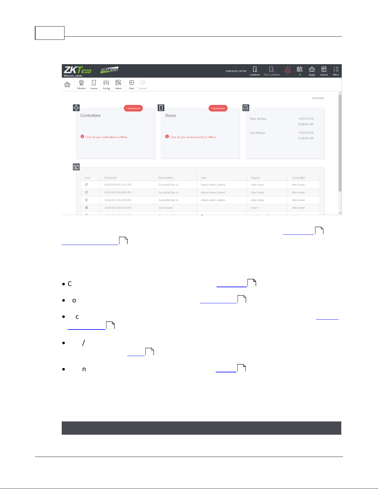
The Home Screen displays a dashboard-style summary of your system, including recent
Event activity. The Menu Bar is available on this screen, as it is on every screen in the
application.
21
20
Home Screen Dashboard
Copyright©2019 ZKTECO CO., LTD. All rights reserved.
Page 8
Atlas Series User Guide8
click to enlarge
Potential security issues and problems are highlighted in red, including Lockdown and
Emergency Unlock counts. You can click the links for more information. You can always
return to this screen using the Home button towards the upper right on the Main Menu.
The dashboard summary squares include:
·
Controllers status summary — link takes you to Hardware
·
Doors status summary — link takes you to Door Status
·
Backup status (next scheduled backup, most recent backup) — link takes you to Backup
and Restore
·
Web/Mobile connected client count, and whether the Admin password has been
secured (Go to the Users module and change the Admin password to secure it.)
·
Recent Events — + View More link takes you to Events
The exact summary squares visible depend on your User Role. Also note that when
logging into a Secondary Controller, the summary squares are extremely limited due to
the fact that the Secondary Controller gets its data from the Primary Controller.
113
56
26
99
38
22
111
Main Menu
Copyright©2019 ZKTECO CO., LTD. All rights reserved.
Page 9
Introduction 9
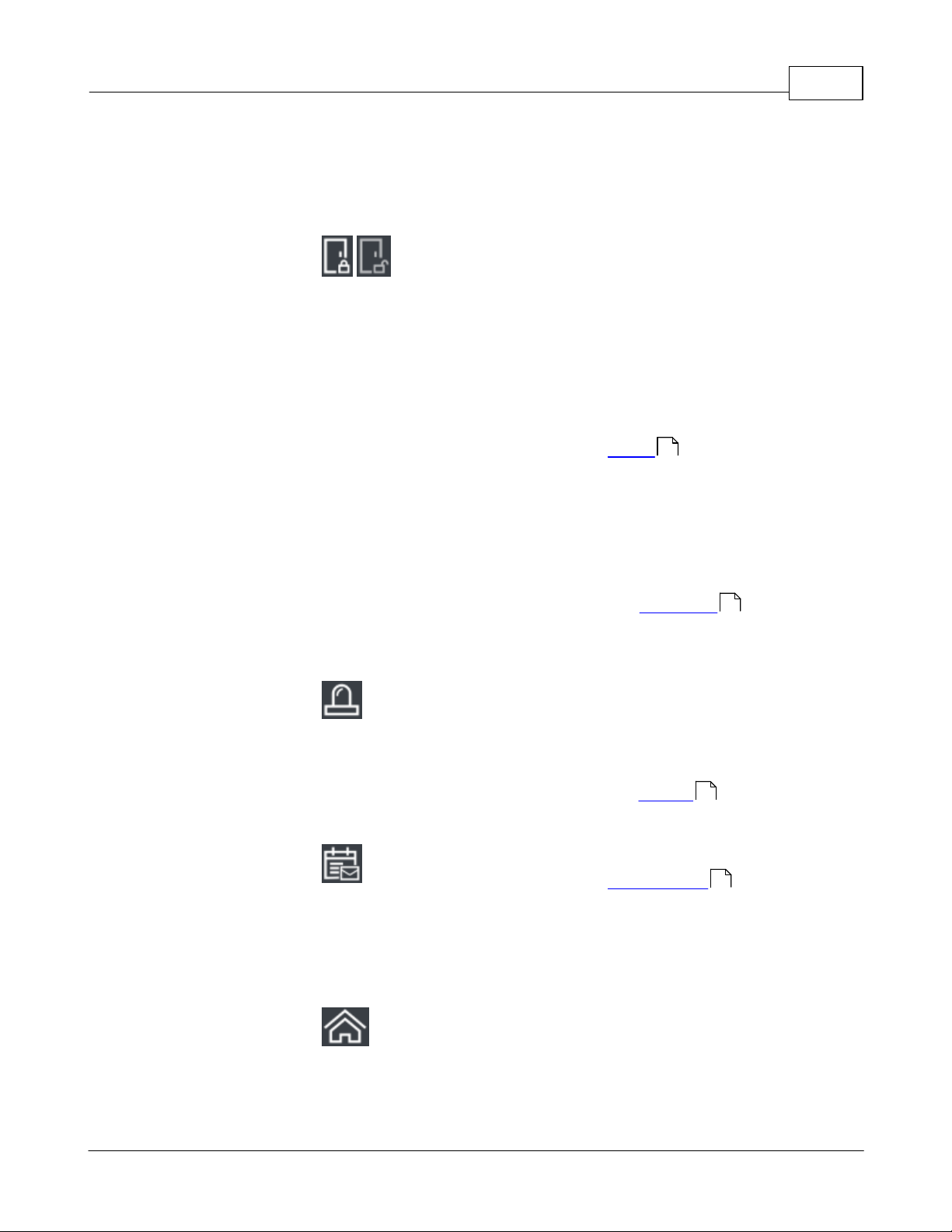
The Main Menu bar is at the top right of all screens.
Lockdown and
Clear
Lockdown
Click Lockdown to quickly lock
all Doors in an emergency
situation. When a global
lockdown is in effect, a
message is displayed
prominently in the Menu Bar.
Note that initiating a
lockdown will create an
Alarm by default.
Click Clear Lockdown to reenable access and return
Doors to their default or
Scheduled Door Mode.
See Lockdown for more
information.
Alarms
When there are active Alarms,
this icon will be red or yellow
and show the number of
current Alarms. Click to go to
the Alarms screen.
Notifications
Click to view the
Notifications you have
subscribed to. The number of
Notifications waiting for you is
displayed under the icon.
Home
Return to the Home Screen.
24
111
24
17
Copyright©2019 ZKTECO CO., LTD. All rights reserved.
Page 10
Atlas Series User Guide10
Layouts
Layouts allow you to view
multiple features or screens at
a time. For example, select a
3-panel layout to work on
Access Levels and
Schedules while viewing
live Events . Each panel has
its own navigation menu.
Select the single-pane layout
to return to the standard
view.
Menu
Opens a menu showing several
miscellaneous options. See
below.
The exact Main Menu items available depend on your User Role . Also note that
when logging into a Secondary Controller, the menu items are extremely limited,
because it is mostly managed by the Primary Controller.
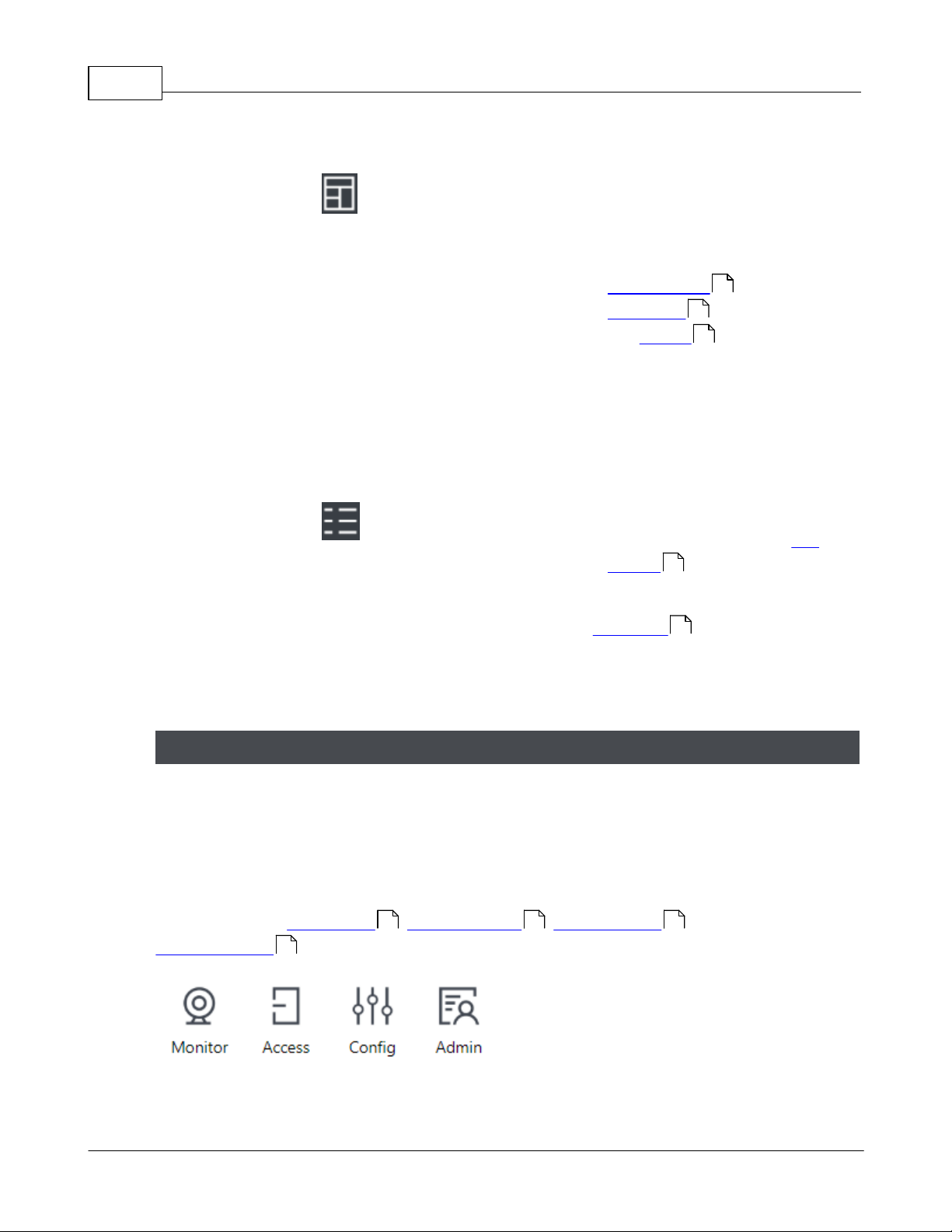
The Navigation Menu contains items for all of the main screens in the application,
organized under four subject buttons. The Navigation Menu is repeated in every panel of
multiple-panel layouts. This help manual is organized like the menu—four main sections
containing a subtopic for each menu item.
The subjects are Monitoring , Access Control , Configuration , and
Administration .
48
49
22
7
92
Navigation Menu
92
21 37 54
Copyright©2019 ZKTECO CO., LTD. All rights reserved.
Page 11
Use the Back and Forward buttons to navigate through your own history of accessing the
screens. (The browser's navigation buttons do not work inside the Web Management
Application).
The exact Navigation Menu items available depend on your User Role . Also note that
when logging into a Secondary Controller, the menu items are extremely limited, because
it is mostly managed by the Primary Controller.
Menu Button Items
Language
Set's the language for the current User. Saved as the default for
this User.
Available languages depend on your software license . Contact
your authorized ZKTeco representative for license upgrades.
Preferences
Set's the preferences for the current User. Saved as the default for
this User. The preferences are
·
"Items per Page", the number of items shown in one page of a
list , and
·
"Card Enrollment Point ."
Save Logs...
Creates a file containing program logs and other information for
investigating problems. Use when asked to by technical support. If
possible, save the logs right after you see a problem, and have it
available when contacting technical support.
Help
Opens this Help.
Introduction 11
92
12
117
15
Copyright©2019 ZKTECO CO., LTD. All rights reserved.
Page 12
Atlas Series User Guide12
About
Opens a window showing product information, including your
current version and licenses. Register or add licenses on this
screen.
Sign Out
Log out of the Web Management Application, returning to the
Login Screen.
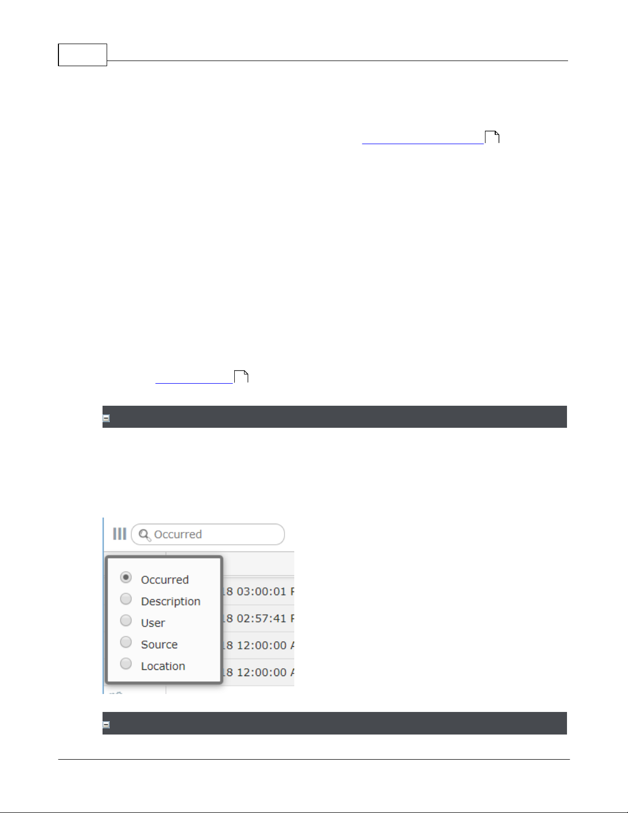
To search in a column, enter the text in the box at the top of the list.
The default, gray text is the column that will be searched. Click the magnifying glass to
change the column.
1.2 Using List Views
List Views show a list of items in columns. In many cases, the columns can be changed,
moved around, and searched.
15
Note that Property Views also display a list on the left, which has the same controls.
14
Searching
Column Selection
Copyright©2019 ZKTECO CO., LTD. All rights reserved.
Page 13
Introduction 13
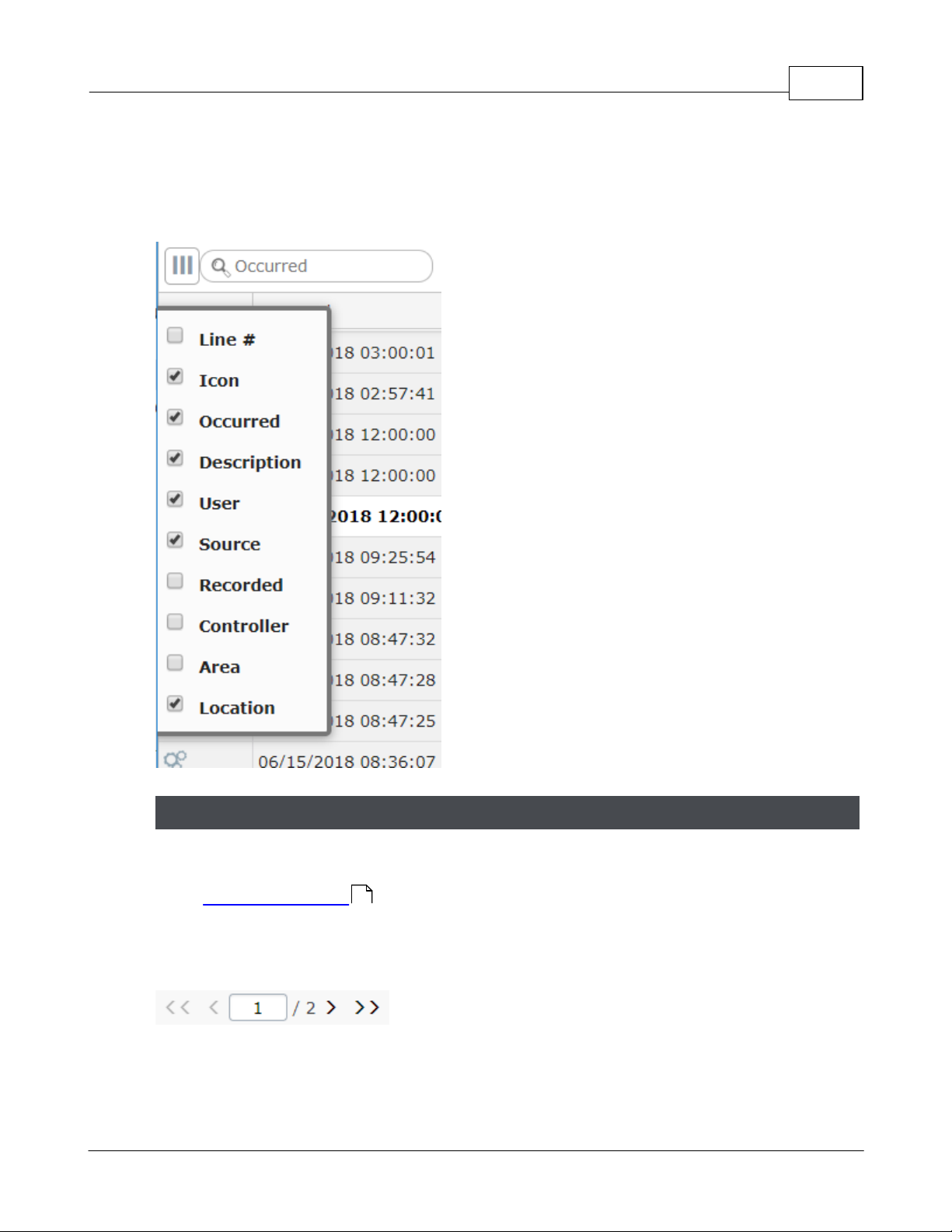
You can move the displayed columns by clicking and dragging on the column title.
Click the triple bar icon to select which columns to show.
Lists run to extra pages when the number of items exceed your personal Items per Page
set in Menu: Preferences .
This box appears at the bottom of the list when there are pages. You can go forward or
back a page, go to the end or beginning, or enter a page number.
Paging
7
Copyright©2019 ZKTECO CO., LTD. All rights reserved.
Page 14
Atlas Series User Guide14
click to enlarge
1.3 Using Property Views
Most configuration is viewed or changed in Property Views. These screens display a list of
items you have created on the left, with their properties on the right.
The list can be searched using the same tools as in List Views .
12
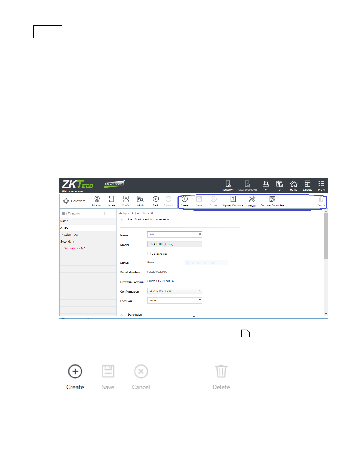
Use the buttons above the properties to create new items, save changes, or delete items.
Many Property Views add additional action buttons to the menu bar. These are generally
specific to the kind of screen they are displayed on, and their functions are described in
Copyright©2019 ZKTECO CO., LTD. All rights reserved.
Page 15
the documentation for the specific screens. These are shown in gray if they don't apply to
the currently selected item.
1.4 Logging In and Passwords
To access the Web Management Application, open a web browser and enter the IP
address of the Primary Controller provided by your Atlas Series administrator. (In some
browsers, you must type "https://" before the address.) You should "bookmark" this link.
Your browser might display an insecure site warning. The means to bypass this varies
among browser applications, but should be shown on the error page as a link labeled
"Advanced", "Details", "More Information", or something similar. You can prevent this
warning for all Users by installing a signed HTTPS certificate .
Introduction 15
108
Enter the username and password provided by your administrator. If you have lost the
password for the "admin" user, see Password Reset .
You cannot change your password unless you have access privileges to edit Users . Ask
your administrator for password changes.
1.5 Product Registration and Licenses
Registration is required if you ever need to reset your system password , and optionally
allows ZKTeco to contact you about software updates and other information.
Additional licenses let you increase the capacity of your Atlas Series system. You can
·
increase the number of Doors or Secondary Controllers allowed,
·
increase the number of mobile device connections, and
120
38
120
·
add to the languages the system supports.
(Note that "Out" Doors are not counted towards your maximum authorized doors.)
Copyright©2019 ZKTECO CO., LTD. All rights reserved.
Page 16

Atlas Series User Guide16
Follow these steps to register for the first time or to update your registration information.
1. Registration can be started in two ways:
a. When you log in the first time, click Register Now in the Register Your Product pop-
up window, or
b. Select Menu: About, and click the Register button. (If you have previously
registered, the link is Update Registration.)
2. Click the New Registration button in the next pop-up window. (If you have previously
registered, the button is View/Update Registration.)
3. Fill in the registration information. Asterisks indicate required information. The email
address you enter must be able to receive your registration information.
4. Submit your registration automatically or by email.
a. For automatic registration, click the Submit Online button. You will see a progress
window followed by a success message.
b. For email registration:
i. Click the Offline Registration button. Read the instructions in the following
window.
ii. Click the Download registration file link, and save the registration data file to
your computer.
iii. Create and send an email message by clicking the email link or entering it in your
email program. Your email must contain the registration data file as an
attachment, with its original name. The subject and text of the email do not
matter.
You will receive a registration confirmation file by reply email. When you do,
1. Open the email and save the attachment to your computer.
Contact your authorized ZKTeco representative for license upgrades. Current license
information can be viewed on the About screen.
7
How to Register
Copyright©2019 ZKTECO CO., LTD. All rights reserved.
Page 17

2. Click the Upload Confirmation button. (If you have already exited from registration,
then return to this option by selecting Menu: About and clicking the Register button.)
3. Find and open the registration confirmation file you saved.
You should see a "Registration successful" message window.
How to Add Licenses
When you acquire an additional license, you will receive a license file from ZKTeco. Save
this file on your computer, then:
1. Select Menu: About.
2. Click the Upload Additional Licenses button.
3. Click on the Browse button, and Open the license file you received.
4. Click OK. Your new capabilities should be listed on the About screen.
·
Home Screen and Menus
·
Password Reset
Introduction 17
Related Topics
7
120
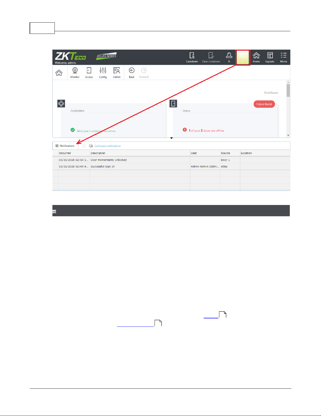
1.6 Notifications
Notifications allow each user to select certain Events they wish brought to their
attention. When one of these Events occurs, it will appear in the Notification window of
that User, and remain there until acknowledged.
Notifications can be copied to you by email.
Click the Notifications icon in the Menu Bar to open and close the Notifications Window
at the bottom of the screen.
22
Copyright©2019 ZKTECO CO., LTD. All rights reserved.
Page 18
Atlas Series User Guide18
click to enlarge
Configure Notifications to select the Events that generate Notifications for the current
User. No Notifications are created unless you select them.
1. Click Notifications on the Menu Bar.
2. Click the Configure notifications link in the Notifications Window.
3. If desired, check Send a Copy of Notifications by Email.
? Otherwise, Notifications are displayed in the Web Management Application
only.
? You must have an email address configured in Users and an email server
configured in Email Settings .
4. Check the Event categories and types you wish to receive Notifications for.
? Select a category to receive Notifications for all Event Types in that category, or
? Expand the category and select specific Event Types.
Configuring Notifications
106
38
Copyright©2019 ZKTECO CO., LTD. All rights reserved.
Page 19
5. Click Save.
Clearing Notifications
To clear Notifications in the list, click one of the buttons next to Configure notifications.
— Select one or more Notifications and click this to clear them.
— Click to clear all Notifications.
Note that since Notifications are on a per-User basis, if one User clears a Notification,
other Users' Notifications are unaffected.
To receive copies of all Notifications by email, you must configure email for the system
and for yourself.
1. Configure the Web Management Application Email Settings .
2. Enter an Email Address on your User page.
3. Select Send a Copy of Notifications by Email under Configure notifications, above.
To define the maximum number of Notifications per User:
1. Go to System Settings .
2. Enter the Maximum Notifications per User.
3. Click Save.
The oldest Notifications are deleted when the maximum number is reached.
·
Email Settings
Emailing Notifications
Introduction 19
106
38
Maximum Number of Notifications
100
Related Topics
106
Copyright©2019 ZKTECO CO., LTD. All rights reserved.
Page 20

Atlas Series User Guide20
·
System Settings
100
1.7 Emergency Features
Your Atlas Series system is designed with a number of important features used to aid in a
variety of emergency situations.
·
Lockdown can be configured and used to secure facilities against an active intruder
111
or threat.
·
Emergency unlock can be configured and used to aid access by emergency personnel
113
in the event of an active emergency condition signaled from another system
·
Duress PINs can be used to allow users to signal a duress condition during their
114
otherwise normal access
·
Emergency Codes can be configured and used to allow access to emergency or
48
security personnel using a PIN-code only, regardless of Door Mode (including lockdown),
or Multi-User Access Rules.
·
Muster can be used to aid in the tracking of users during an evacuation, or
30
evacuation drill
·
Alarms and Notifications can be configured and used to make sure the correct
24 17
personnel are aware of potential emergency situations
Important: All emergency functions intended to be used in your system should be tested
ahead of time, to ensure that everything is configured and working correctly.
Important: These emergency functions are designed as a supplement to, but not a
replacement for, life-safety infrastructure for your facility. Life-safety functions are
regulated by country- and region-specific fire codes. Please refer to these when designing
and configuring your system to ensure compliance.
Copyright©2019 ZKTECO CO., LTD. All rights reserved.
Page 21
2 Monitoring
Events is a live view of everything that happens in the system.
Alarms shows Events that you have determined should be immediately reviewed and
action taken. Each Alarm must be acknowledged and cleared by someone who has
resolved the problem. Note that Events do not become Alarms until you set up Alarm
Triggers .
Door Status shows the current state of every Door, whether it be on line, locked,
alarmed, and so forth.
Maps show similar status as Door Status, with visual indicators displayed on a Map of
your facilities. The Maps must first be created in Maps (Configuration) .
Muster is a special report that can show you where Users are in an emergency or an
evacuation drill. To use the Muster report, you should first designate Muster Areas. Users
must check in at the Muster Areas to indicate that they are safely out of the facility.
The remaining menu items are simple reports.
Audits shows configuration changes and actions performed by Users logged into the
Web Management Application.
Event History is a report view of Events, with the ability to display a larger number
Events and export to CSV and PDF.
Alarm History shows all Alarms, including those that have been resolved (resolved
Alarms are not shown on the live Alarms screen).
User Access Level Report shows which Users have a specific Access Level .
Monitoring gives you live views of what's occurring in the system, and printable reports of
configuration and history.
Live Monitoring
22
24
87
26
Monitoring 21
28
Reports
30
31
33
34
36 48
82
Copyright©2019 ZKTECO CO., LTD. All rights reserved.
Page 22
Atlas Series User Guide22
User Door Report shows which Users have access to a specific Door. This report
includes Doors directly assigned to the Users as well as those assigned via an Access
Level .
·
Reports and Printing
Filter
Opens a panel where you can restrict the Events you wish to see in
the list view. Your filters remain in place each time you log in.
Settings take effect when you click the Search button, at the
bottom of the panel. The Reset button clears all filters.
User and Device Filters
The display shows only the Events that match all the filters you
specify. Note that the Name filters are case-insensitive, and will
find partial matches. For instance, if you enter "john", the display
will also show Events for "John", or "Johnny".
Event Type Filter
The display shows Events that match any of the Event Types you
have checked. If nothing is checked, all Events are displayed.
48
Related Topics
2.1 Events
Events displays a real-time list of Events occurring within the system. Events that trigger
Alarms are displayed in a configurable color.
36
115
24
To receive an email when important Events occur, see Notifications .
Up 1000 Events can be displayed. To view more Events, use Event History .
Menu Buttons
17
33
Copyright©2019 ZKTECO CO., LTD. All rights reserved.
Page 23

Clear
Clear the current list of Events from the display, so only new Events
appear. Events are hidden, but not deleted.
Events Columns
Some columns will be empty for certain types of Events.
Icon
Category of Event
Occurred
When the Event actually occurred (determined by the Controller
on which it occurred)
Description
Text of the Event
User
The User associated with the Event. This could also be a Shared
Access Code , Emergency Code , or credential (card, PIN) that is
not assigned to a single User.
Source
The device that recorded the Event. For door access Events, this is
a Door. For other Events, this may be a Controller, input, output,
or other device.
Recorded
(Hidden by default) The time the Event was received and recorded
by the Primary Controller. This only differs from Occurred if the
Secondary Controller where it occurred was offline with the
Primary Controller at the time of the Event.
Controller
(Hidden by default) Controller where the Event occurred
Area
(Hidden by default) If the Event is associated with an Area (for
example a Door entering an Area), the Area is indicated here.
Monitoring 23
38
46 48
80
Copyright©2019 ZKTECO CO., LTD. All rights reserved.
Page 24
Atlas Series User Guide24
Location
(Hidden by default) If the source is associated with a Location , it
is indicated here.
The oldest Events are are automatically archived to CSV files on the Primary Controller
when the maximum number is reached. To download the archived data, see Archive
Downloads .
To change the maximum number of Events in the system, go to System Settings and set
the Maximum Events in Database.
·
Using List Views
·
System Settings
·
Event History
Event Archiving
107
Related Topics
79
100
2.2 Alarms
Alarms are issues that may indicate a potential security threat or other problem. They
cause a warning display on the Main Menu bar, and they remain in effect until they
are resolved by a User.
Alarms are triggered by Events . Some Event Types are set to trigger Alarms by
default. You can make more Events trigger Alarms, or change the defaults, in Alarm
Triggers .
To receive an email when an Event causes an Alarm, see Notifications .
12
100
33
7
22 134
87
17
The color of an Alarm is determined by its state, which can be:
·
New (Red) — this means the Alarm is active.
Copyright©2019 ZKTECO CO., LTD. All rights reserved.
Page 25

Monitoring 25
Acknowledge
Indicates that a User is aware that the Alarm has occurred,
changing its state to "Acknowledged." The User is indicating they
have accepted an agreed level of responsibility for resolving the
issue.
Resolve
Indicates that any problem has been dealt with, changing its status
to "Resolved." The Alarm will be removed from this screen, but can
be viewed in Alarm History . Alarms must be acknowledged
before they can be resolved.
Acknowledge
All
Acknowledges all Alarms that are in the "New" state
Resolve All
Resolves all Alarms that are in the "Acknowledged" state
Description
Description of the triggering Event
Source
The device that recorded the Event. For door access Events, this is
a Door. For other Events, this may be a Controller, or other device.
·
Acknowledged (Yellow) — this means that some User has acknowledged the Alarm.
Resolved Alarms are removed from the list. They can be viewed in Alarm History .
Repeated Alarms are merged into a single Alarm. The Count column shows how many
times it has occurred, and Last Recorded shows the most recent time it occurred. Alarms
are merged when they are identical in all ways except for the date and time. Once
resolved, any new occurrence will make a new Alarm.
34
Menu Buttons
34
Alarms Columns
Copyright©2019 ZKTECO CO., LTD. All rights reserved.
Page 26
Atlas Series User Guide26
Priority
The priority of this Alarm (as configured in Alarm Triggers )
Count
The number of times the triggering Event has occurred and merged
into one Alarm
First Recorded
Time of the first triggering Event
Last Recorded
Time of the most recent duplicate triggering Event
State
"New" or "Acknowledged". The "Resolved" state is only visible in
Alarm History . The state determines the color (see above).
Location
Location where the triggering Event occurred
Area
(hidden by default) Area where the triggering Event occurred
·
Using List Views
·
Alarm Triggers
·
Alarm History
·
Emergency Features
87
34
Related Topics
2.3 Door Status
79
80
12
87
34
20
Door Status displays a real-time list of all Doors and their status. You can also use Manual
Commands to unlock a Door temporarily or change the Door Mode.
Menu Buttons
115
Copyright©2019 ZKTECO CO., LTD. All rights reserved.
Page 27
Manual
Commands
Send a Manual Command to the selected Door, such as to
temporarily unlock it or change its Door Mode.
Door Status Columns
Door
The name of the Door
Communicatio
ns
"Online" or "Offline"
Door Mode
The Door Mode , such as "Card Only" or "Card and PIN"
Status
Whether the Door is "Locked" or "Unlocked" and "Open" or
"Closed"
Errors
Shows "Door Forced" or "Door Held", "Reader Offline", and
"Tamper" errors
Alarm
Indicates if an active Alarm exists for the Door
Type
The type of Door
·
In
·
Out
·
Muster Point
·
Card Enrollment Point
Location
The Door's Location
Monitoring 27
115
142
Copyright©2019 ZKTECO CO., LTD. All rights reserved.
24
79
Page 28
Atlas Series User Guide28
·
Using List Views
·
Manual Commands
Related Topics
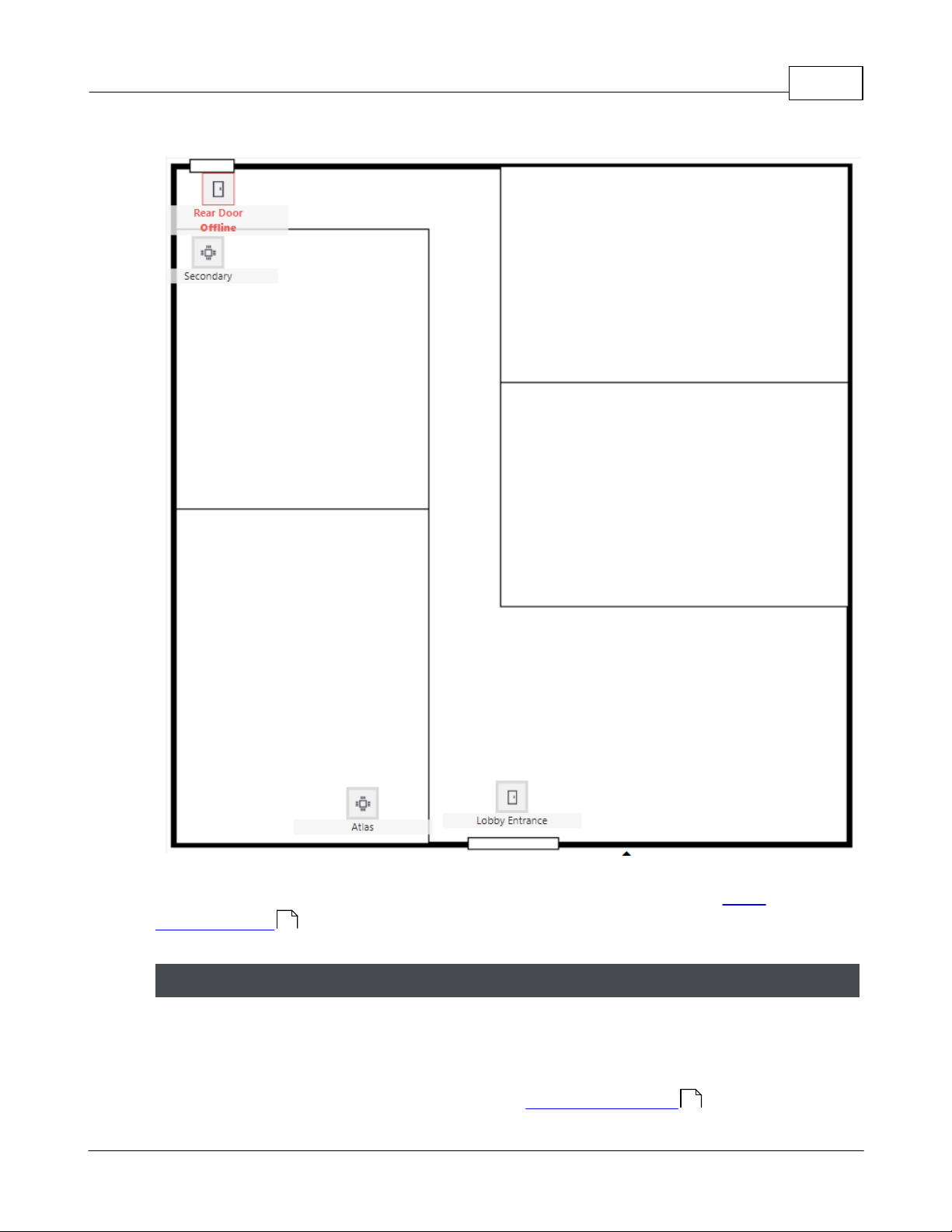
2.4 Maps
The Maps view is used to show the status of your Doors and Controllers on graphical
backgrounds, for example, on Maps of your building or campus. It highlights all problems
in red, and allows sending commands to Doors. Maps may also have links to other Maps
for easy navigation.
In this example there are two Doors and two Controllers. The "Rear Door" is offline and
should be checked on. They gray icons represent normal operation.
12
115
Copyright©2019 ZKTECO CO., LTD. All rights reserved.
Page 29
Monitoring 29
Click to enlarge.
Manual
Commands
Click on a Door to enable the Manual Commands button,
allowing commands such as temporarily unlocking it, or
changing its mode. See Manual Commands .
Before they can be viewed, Maps must be created and configured in the Maps
(Configuration) screen.
82
Menu Buttons
Copyright©2019 ZKTECO CO., LTD. All rights reserved.
115
Page 30

Atlas Series User Guide30
Zoom In / Zoom
Out
Make the Map larger or smaller. When zoomed in, you can click
and drag on the Map to see different areas.
·
Using List Views
·
Maps (Configuration)
·
Manual Commands
Muster points can be created when creating 1-door model Controllers .
1. Go to Hardware .
2. Select a 1-door model.
3. For Configuration, select a Muster option, such as In Only + Muster Point.
You can also modify 1-door or 2-door Controllers or enrollment points into Muster Points.
For example:
1. Go to Hardware .
Related Topics
2.5 Muster
The Muster report shows the last known location of Users who are not registered in a safe
Area. Use this report when evacuating a building or buildings or performing an evacuation
drill. This lets security personnel know who is still inside the building(s).
12
82
115
Users counted as "safe" are
·
Users who have exited to Global Out or reported at a Muster Point and
·
Users who have not used any Door within 24 hours.
Muster reports may or may not include Users who have used a Shared Access Code or
Emergency Code.
Creating a Muster Point
56
70
56
Copyright©2019 ZKTECO CO., LTD. All rights reserved.
Page 31

2. Select a 1-door or 2-door Controller.
3. Turn the spare readers into Muster Points.
Generating a Muster Report
1. Go to Muster. A list of existing muster points is displayed at the bottom.
2. Select List By — Last Name or Area.
3. Select Orientation — Landscape or Portrait.
4. Click Generate.
·
Reports and Printing
·
Hardware
·
Emergency Features
Orientation
Displays the report in "Portrait" or "Landscape" view
Audit Type
·
Database Change — shows changes to items in the database
(Users, Doors, Access Levels, etc.), and enables further filtering
Related Topics
Monitoring 31
2.6 Audits
Audit reports list configuration changes and actions performed by Users of the Web
Management Application. Use these reports to see who unlocked a Door, gave access to a
User, configured Access Levels, and other system operations.
When generating the report, you are prompted for the following options. Options vary
based on the Audit Type selected. Click Generate to create the report.
Report Options
115
56
20
Copyright©2019 ZKTECO CO., LTD. All rights reserved.
Page 32

Atlas Series User Guide32
options.
·
Manual Command — shows Manual Commands executed on
Doors, and enables further filtering options.
·
Any/All — both of the above
User
If selected, the report will only show actions taken by a specific
User.
From / To
Limits the report to a date range
Change Type
For Database Change, which types of changes to include:
·
Inserted
·
Updated
·
Deleted
·
Any/All
Object Type
For Database Change, which types of items to include (User, Door,
etc.)
Manual
Command
For Manual Command, limits the report to one command type
Device
For Manual Command, limits the report to a single Door
·
Reports and Printing
·
Users
115
Related Topics
38
115
Copyright©2019 ZKTECO CO., LTD. All rights reserved.
Page 33

·
Manual Commands
2.7 Event History
Export CSV
Export the displayed Events to a data file appropriate for importing
into program like Excel. ("CSV" designates the "comma separated
values" file format.)
Export PDF
Save the displayed Events as a printable report in PDF format.
Settings take effect when you click the Search button, at the bottom of the panel. The
Reset button clears all filters.
Date and Time Filter
Shows only Events from the specified time period.
User and Device Filters
The display shows only the Events that match all the filters you specify. Note that the
Name filters are case-insensitive, and will find partial matches. For instance, if you enter
"john", the display will also show Events for "John", or "Johnny".
Event Type Filter
The display shows Events that match any of the Event Types you have checked. If nothing
is checked, all Events are displayed.
Event History displays a list of Events according to a filter, and allows export to CSV and
PDF. The maximum number of Events in this screen is limited only by the number of
Events in the database. For a real-time view, see Events .
Menu Buttons
Monitoring 33
115
22
Filter Pane
Events Columns
Copyright©2019 ZKTECO CO., LTD. All rights reserved.
Page 34

Atlas Series User Guide34
See Events .
The oldest Events are are automatically archived to CSV files on the Primary Controller
when the maximum number is reached. To download the archived data, see Archive
Downloads .
To define the maximum number of Events in the system, go to System Settings and set
the Maximum Events in Database.
·
Using List Views
·
Reports and Printing
·
System Settings
·
Events
Filter
Opens a panel where you can define the kind of Alarms you wish to
see.
22
Event Archiving
107
Related Topics
100
22
2.8 Alarm History
Alarm History displays all Alarms, including resolved ones. Resolved Alarms are hidden in
the Alarms screen. This view does not update in real-time or allow you to acknowledge
24
or resolve Alarms.
Menu Buttons
12
115
100
Copyright©2019 ZKTECO CO., LTD. All rights reserved.
Page 35

Monitoring 35
Settings take effect when you click the Search button, at the
bottom of the panel. The Reset button clears all filters.
Date and Time Filter
Display Alarms from a range of dates and times.
User and Device Filters
The display shows only the Events that match all the filters you
specify. Note that the Name filters are case-sensitive. For instance,
if you enter "john," the display will not show Events for "John."
Event Type Filter
The display shows Alarms that match any of the Event Types you
have checked. If nothing is checked, all Alarms are displayed.
Export PDF
Save the displayed Alarms as a printable report in PDF format.
See Alarms .
·
Using List Views
·
Reports and Printing
·
Alarms
·
Alarm Triggers
·
Emergency Features
Alarms Columns
24
Related Topics
12
24
87
115
20
Copyright©2019 ZKTECO CO., LTD. All rights reserved.
Page 36

Atlas Series User Guide36
·
Reports and Printing
·
Users
·
Access Levels
·
Reports and Printing
·
Users
·
Access Levels
2.9 User Access Level Report
User Access Level Report creates a report of all Users who have a selected Access
48
Level .
This report does not include Shared Access Codes or Emergency Codes .
Related Topics
38
48
2.10 User Door Report
User Door Report creates a report showing which Users have access to a specific Door.
This report includes Doors directly assigned to the Users as well as those assigned via an
Access Level.
This report does not include Shared Access Codes or Emergency Codes .
38
46 48
115
38
46 48
This report also excludes Users with no credentials (no cards, PIN, or biometrics).
Related Topics
115
38
48
Copyright©2019 ZKTECO CO., LTD. All rights reserved.
Page 37

3 Access Control
Create Users to provide door access to individual Users who use a credential such as a
card, a PIN, or a biometric fingerprint. This is the most common door access method and
allows you to track who comes and goes. You can simply give each User unrestricted 24/7
access to Doors, or further restrict their access using the following features.
Set up Schedules to allow access only at certain times, such as during business hours.
Create Access Levels to predefine a set of Doors and Schedules that can be quickly
assigned to multiple Users.
Specify Special Days to restrict access more than usual for holidays, corporate events,
or other days when access rules should differ. Special Days are used in Schedules.
Create Shared Access Codes , which creates PIN codes that anyone can use to unlock
deisgnated Doors.
The following features are used in special situations:
Emergency Codes are PIN codes that unlock Doors in an emergency.
Multi-User Access requires more than one User to present credentials to unlock
sensitive areas. For example, a rule could be created such that three Users must present
their card to open a Door.
Door Mode Schedules function like normal Schedules but are used in the Doors
configuration to schedule Door Mode changes.
The Access Control menu is primarily for determining who can open Doors, when, and
how (cards, PINs, and biometrics).
You can also perform related tasks such as creating Users for the Web Management
Application and creating Door Mode Schedules .
Access to Doors
38
Access Control 37
50
49
48
51
46
Special Features
48
52
50 49 73
Copyright©2019 ZKTECO CO., LTD. All rights reserved.
Access to the Web Management Application
Page 38

Atlas Series User Guide38
Web Management Application Users are added in the same Users configuration
screen. A User can have both Door access and web application access.
Filter
Displays a panel above the list where you can search for a User on
several properties. Users are displayed if they match all filters.
Settings take effect when you click the Search button, at the
bottom of the panel. The Reset button clears all filters.
Import
See Importing Users from a CSV File .
Forgive
Resets the selected User's anti-passback status. Use this when antipassback rules are preventing a User's access, and this needs to be
overridden.
For the complete list and more details see User Properties .
First Name
and
Last Name
The User’s first and last name. Both required, maximum 32
characters each.
3.1 Users
Users can be created for the following purposes:
·
Cardholders who can access Doors.
·
Users who can log into the Web Management Application.
A single User can have both Door and application access.
Menu Buttons
38
45
Key Properties
40
Copyright©2019 ZKTECO CO., LTD. All rights reserved.
Page 39

Access Control 39
Photo
A photo of the User. This is shown here, and can be printed on a
card . To add or change the photo, click the photo image and
select an image from your computer. Supported image formats are
PNG, JPEG, and GIF.
Role
Cardholder Only for cardholder. The other Roles provide access to
the Web Management Application. Each Role provides a different
level of access; see User Roles . Users with the ability to log in
also can have Door access.
Username and
Password
If Role is not Cardholder Only, this is the username/password used
to log in to the web application.
Cards
Add any number of cards that will be used for access. You can use
a Card Enrollment Point to add a card number.
Adding a card does not provide access; the User will also need
Access Levels or Doors assigned, below.
Fingerprints
Shows whether the User has any fingerprints enrolled, and allows
them to be enrolled. (Fingerprints are only available if the Primary
Controller supports biometrics.)
PIN
PIN (Personal Identification Number) for the User, numeric only.
Click Create New to generate a random, unique PIN. The length
must match the PIN length defined in System Settings . (The
default is 4 characters).
Access Levels,
Door Access
·
Add Access Levels that have been defined, and/or
·
Add Door Access entries to customize access for this User.
Card Design
Use to print cards .
45
92
117
100
48
45
Copyright©2019 ZKTECO CO., LTD. All rights reserved.
Page 40

Atlas Series User Guide40
·
Using Property Views
·
User Properties
·
User Roles
·
Duress
·
Access Levels
·
Anti-Passback
·
Printing Cards
Status
Displays whether the current User's status is Valid or Invalid. The
status will be Invalid if the current date is outside of the and Valid
To range, or if Disable User is checked.
First Name and
Last Name
The User’s first and last name. Both required, maximum 32
characters each.
Photo
A photo of the User. This is shown here, and can be printed on a
card . To add or change the photo, click the photo image and
select an image from your computer. Supported image formats are
PNG, JPEG, and GIF.
Related Topics
40
92
114
48
118
45
14
3.1.1 User Properties
The following are the properties available on the Users screen:
38
Identity
45
Copyright©2019 ZKTECO CO., LTD. All rights reserved.
Page 41

Access Control 41
Personnel ID
A unique identifier, such as an employee ID. Maximum 32
characters
Role
Cardholder Only for cardholder. For Users with the ability to log in,
select another Role. See User Roles . Users with the ability to log
in also can have cards.
User Group
Select a User Group which will be used when applying Multi-User
Access rules . This is used if multiple Users are required to
present their credentials to open a Door.
Username
If Role is not Cardholder Only, this is the username used to log in to
the web application.
Password
If Role is not Cardholder Only, this is the password used to log in to
the web application.
Language
The User's preferred language, which will be
·
displayed on card readers that support multiple languages (such
as some OSDP readers), and
·
the User's default language in the Web Management Application.
Available languages depend on your software license . Contact
your authorized ZKTeco representative for license upgrades.
Valid From
The date when access should begin. The default is the current date.
This applies to both Door access and Web Management Application
access.
Until Further
Notice, Valid
To
If Until Further Notice is checked, then the User's access never
expires. If it is unchecked, then the Valid To date must be provided,
which determines when the User's access expires. This applies to
both Door access and Web Management Application access.
92
87
52
Copyright©2019 ZKTECO CO., LTD. All rights reserved.
15
Page 42

Atlas Series User Guide42
Disable User
If checked, the User's access is disabled. This applies to both Door
access and Web Management Application access.
Vacation From,
Vacation To
If this date range is entered, it is a vacation date range during which
the User's Door access is suspended. Web Management Application
access is not affected by vacation dates.
Email
The User’s email address. This is required for the User to receive
system emails such as Notifications .
Mobile Phone
The User’s mobile phone number.
Custom 1-4
Custom fields corresponding to those configured in System
Settings .
Cards
Click Add to add card numbers for Door access. Click Enabled to
enable or disable a card. To enter a card number by swiping the
card, see Card Enrollment Points .
Fingerprints
Shows whether the User has any fingerprints enrolled, and allows
them to be enrolled.
Fingerprint enrollment requires a ZKTeco USB enrollment reader
and its Fingerprint Driver software (available on the Downloads
page at ZKTecoUSA.com).
Additional Information
17
100
Access
117
Copyright©2019 ZKTECO CO., LTD. All rights reserved.
Page 43

Access Control 43
PIN
The PIN (Personal Identification Number) used for Door access.
Numeric only. The length must match the PIN length defined in
System Settings (default is 4 characters).
·
PIN numbers must be unique, including Duress PIN codes, Shared
Access Codes , and Emergency Access Codes .
·
Click Create New to generate a random unique PIN number.
·
Click Clear to clear the PIN.
Duress PIN
The duress PIN generates a duress access Event when used in place
of the normal PIN. Access is still granted if all other normal access
conditions are met. See Duress for more details. For Duress PIN
Type:
·
Select None if the Duress PIN is not used.
·
Select Add 1 to Last Digit to add one to the last digit, only, of the
normal PIN. For example, a normal PIN of 1111 would then have a
duress PIN of 1112, and a normal PIN of 9999 would have a duress
PIN of 9990.
·
Select Explicit to enter an specific Duress PIN for this User.
Numeric only. The length must match the PIN length defined in
System Settings (default is 4 characters).
Use Extended
Door Times
If checked, extended Door unlock and held times are used when this
User is granted access. This is for Users requiring additional time to
get through a Door, for example a person with a disability. The
amount of extra time is set on each Door .
Anti-passback
Exempt
If checked, the User is not subject to anti-passback rules.
100
46 48
114
100
Copyright©2019 ZKTECO CO., LTD. All rights reserved.
75
118
Page 44

Atlas Series User Guide44
Access Doors in
No Access
Mode
If checked, the User can access Doors in No Access mode. This is
typically only for administrators and security personnel.
Access Doors in
Lockdown
Mode
If checked, the User can access Doors in Lockdown mode. This is
typically only for administrators and security personnel.
Access Levels
Access Levels assigned to the User for Door access.
Door Access
Grants this User access to individual Doors during the selected
Schedule. This is in addition to any Access Levels assigned.
Card Design
Select a card design . If selected, a preview is displayed.
Click Print Card to print. When printing, if the card number is a
part of the design, the card number must be selected.
Click Print Receipt if the card is printed to a remote location, and
the recipient must go pick it up.
·
User Roles
·
User Groups
·
Card Enrollment Points
·
Access Levels
111
48
Card Design
83
45
Related Topics
92
87
117
48
Copyright©2019 ZKTECO CO., LTD. All rights reserved.
Page 45

·
Printing Cards
3.1.2 Printing Cards
·
Users
·
Card Designs
·
Reports and Printing
You can print to a specialized printer that writes ID cards. You can also print a paper
receipt for your use as a record or to authorize pickup at a remote printer.
Access Control 45
45
To do either, you must first create Card Designs .
83
To print, select a User, and:
1. Select a card design. (Your choice will be saved for this User.)
2. Click Print Card or Print Receipt.
3. Select a card number from the list.
4. Click Print and follow the prompts.
To complete the prompts, see Reports and Printing .
115
Related Topics
38
83
115
3.1.3 Importing Users from a CSV File
Copyright©2019 ZKTECO CO., LTD. All rights reserved.
A CSV (comma-separated value) file can be add any number of Users using data from
another software program. The other program must be able to export to CSV or a format
you can convert to CSV. The CSV itself must be modified to exactly match the Atlas Series
import format using software such as a spreadsheet editor.
On the Users screen:
38
Page 46

Atlas Series User Guide46
·
Users
·
User Properties
1. Click Import.
2. Click the link to download a template file that includes a sample of the required data
format.
In your own software:
3. Open the file and read the included instructions.
4. Create a copy of the file.
5. Modify the file with data for the users you want to create.
6. Save the file in CSV format.
a. Make sure the file is in plain text and does not include any additional characters or
encoding.
b. For example, if using any non-ASCII characters, the file must be encoded as UTF-8.
On the Users screen:
38
7. Click Import.
8. In the dialog, click Import.
9. Select the file from your computer. The file must have the ".csv" extension.
10.Click Yes to verify and import the file.
11.The number of imported Users is displayed. Click OK, and you will see the newly
imported Users.
Related Topics
38
40
3.2 Shared Access Codes
A Shared Access Code is a PIN that multiple people can use to access specified Doors.
Copyright©2019 ZKTECO CO., LTD. All rights reserved.
Page 47

Access Control 47
Name
Required. Maximum 32 characters.
PIN
The Shared Access Code itself. Numeric only. Click Create New to
generate a random, unique code.
Enabled
Checked to enable, unchecked to disable
Description
Description or comments
Access Rights
·
Add Access Levels , and/or
·
add Door Access entries to directly assign Door/Schedule pairs for
access.
·
Using Property Views
·
Emergency Codes
·
Access Levels
These codes only work when the current Door Mode allows a PIN by itself to open the
142
Door. For example, PIN-Only or any mode that says "or PIN", such as "Card or PIN".
Shared Access Codes do not work with:
·
Doors that are in Card-only mode, Card and PIN, etc.
·
Doors with Multi-User Access rules (because a user group cannot be assigned to a
52
shared access code).
Shared Access Codes are always exempt from anti-passback .
Use of Shared Access Codes will impact the accuracy of a Muster report.
118
30
Shared Access Code Properties
Related Topics
14
48
48
Copyright©2019 ZKTECO CO., LTD. All rights reserved.
48
Page 48

Atlas Series User Guide48
·
Using Property Views
·
Shared Access Codes
·
Access Levels
·
Emergency Features
3.3 Emergency Codes
An Emergency Code is a PIN that allows access to Doors regardless of other settings,
including the Door Mode. (Compare to Shared Access Codes ). It is intended to be used
by emergency and security personnel to gain access in emergency situations.
46
This means that an Emergency Code can access a Door which is under Lockdown .
111
The successful use of an Emergency Code generates an Emergency Code Presented Event.
The Emergency Code Presented Event is configured as an Alarm Trigger by default,
generating an Alarm . The Emergency Code Presented Event can also be used as a
24
Linkage to trigger the activation of an auxiliary output on the Hardware screen.
Emergency Codes are exempt from anti-passback and Multi-User Access . (Compare
to Shared Access Codes .)
46
118 52
Emergency Codes otherwise have the same properties as Shared Access Codes .
Use of Emergency Codes will impact the accuracy of a Muster report for the emergency
30
87
61
46
personnel who use them.
Related Topics
14
3.4 Access Levels
46
48
20
An Access Level is a predefined list of Doors paired with the Schedules during which
access is allowed for each Door. When an Access Level is changed, the new definition
immediately applies to each User or code assigned that Access Level.
Access Levels can be applied to Users , Shared Access Codes , and Emergency
Codes . On each of those screens you can apply one or more Access Levels, and you can
48
38 46
provide customized access to individual Door/Schedule pairs.
Copyright©2019 ZKTECO CO., LTD. All rights reserved.
Page 49

Using the Screen
Click the Add and Remove buttons to add and remove Doors from the list.
Use the ellipsis buttons (...) to change the selected Doors and Schedules.
You can include the same Door multiple times with different Schedules. Access will be
allowed for a given Door during all the Schedules associated with it.
·
Using Property Views
·
Schedules
·
Users
·
Shared Access Codes
·
Emergency Codes
Access will be allowed during all the time periods you create. Click the Add and Remove
buttons to add and remove time periods from the list.
Times (Start-
Stop)
The left-side bar shows the time period access is allowed in
green. You can drag the ends of the green bar to change the time
range. You can also enter the exact times you want in the boxes
Related Topics
49
Access Control 49
14
38
3.5 Schedules
Schedules are used to limit access to certain days and times. They can be used in Access
Levels and anywhere Door access is assigned.
By default, access is not allowed on Special Days .
The built-in "24/7" Schedule allows access at all times, including Special Days.
Using the Screen
46
48
51
Copyright©2019 ZKTECO CO., LTD. All rights reserved.
Page 50

Atlas Series User Guide50
under the bar. Times are entered and shown using a 24-hour
clock (as opposed to "a.m". and "p.m.") Each bar can only have
one time range; to have two time ranges on the same days, add
another entry. The All day button is a convenience to reset the
bar.
Days
The middle bar shows the days that access is allowed in green.
You can click each day to change access, or you can use the
convenience buttons to change the current selection. The
convenience buttons are Weekdays, All days, and Weekend.
Special Days
The right bar appears green if you have included any Special Days
for that time period. Click the bar to select Special Days to
include. In the Special Days selection screen, you may check one
or multiple Special Day types.
Access is normally denied on Special Days. Access will be allowed
if you include the Special Days in the Schedule. For more
information, see Special Days .
·
Using Property Views
·
Special Days
Related Topics
14
51
3.6 Door Mode Schedules
Door Mode Schedules are used to change the mode of Doors at different times. For
instance, they are commonly used to automatically unlock public Doors during business
hours.
See Door Modes for a list of possible Door Modes.
142
51
Copyright©2019 ZKTECO CO., LTD. All rights reserved.
Page 51

Access Control 51
Click the Add and Remove buttons to add and remove time periods from the list.
In the left column, select a single Door Mode. A Door will automatically change to this
mode during the time period defined.
The time periods are defined the same way they are for Schedules. See Schedules .
·
Using Property Views
·
Door Modes
·
Special Days
·
Schedules
Door Mode Schedules are assigned to Doors on the Doors screen.
73
A Door Mode Schedule can have multiple time intervals with different associated modes.
Note that emergency Door Modes cannot be scheduled.
Using the Screen
49
Related Topics
14
142
51
49
3.7 Special Days
Special Days are single calendar days (such as May 5th) where access is denied by default,
even if it would normally be allowed by a Schedule . They can be added to Schedules so
that certain Users do have access on those days.
Special Days are used for holidays, corporate events, and other cases where you do not
want your usual access to be granted. For instance, you might use Door Mode Schedules
to automatically unlock Doors during business hours Monday-Friday, but you do not want
to do that on holidays.
Note that the special Schedule, "24/7", allows access at all times and is not affected by
Special Days.
49
Special Day Types
Copyright©2019 ZKTECO CO., LTD. All rights reserved.
Page 52

Atlas Series User Guide52
Special Days are grouped into a number of Special Day Types. A type is essentially a
calendar. For instance, one type might include all government holidays, while another
might be teacher work days. You can then set different access rules for the different
calendars.
Only Special Day Types can be added to a Schedule. So, you could add access on all
government holidays, but not on a single one, unless you made a type with just that one
day.
In the first section, Special Day Types, you can change the names of the types to
something useful, such as "Government Holidays" or "Teacher Workdays". You may also
change the color assigned to each type. The color has no effect except on this screen.
The second section, Special Days, shows a calendar highlighting all Special Days of all
types in their color. To add or remove a day, click on it.
The two options above the calendar change what happens when you next click on a day.
They cannot change the properties of current Special Days.
·
Select Special Day Type: days added on the calendar will be this type. You cannot add
days if no type is selected.
·
Set as Repeating: when checked, days added on the calendar will be repeating. This
means they will occur every year on the same calendar date. They are displayed with a
small "R", and can be seen on every year.
Note that any single day can only be in one Special Day Type.
·
Schedules
·
Door Mode Schedules
Using the Screen
Related Topics
49
50
3.8 Multi-User Access
Multi-User Access is used to require multiple Users to present their credentials to open a
Door. This is often used for high security areas. For example, an area might require two
Copyright©2019 ZKTECO CO., LTD. All rights reserved.
Page 53

Access Control 53
You must first create one or more User Groups whose members can cooperate to
access a specific Door.
Click the Add and Remove buttons to add and remove User Groups from the Rules list. If
multiple rules are created, they all must be satisfied in order for access to be granted. If
there are no rules in a specific Multi-User Access definition, associated Doors will behave
as if they have no Multi-User Access restriction.
Apply the Multi-User Access rule on the Doors screen .
·
Using Property Views
·
User Groups
·
Doors
managers and one security guard to present their credentials. The credentials they may
submit are those required by the Door's current Door Mode.
Shared Access Codes cannot access Doors with Multi-User Access rules in effect.
Emergency Codes are exempt from Multi-User Access rules.
46
48
Using the Screen
87
73
Related Topics
14
87
73
Copyright©2019 ZKTECO CO., LTD. All rights reserved.
Page 54

Atlas Series User Guide54
Before doing any configuration, it's important to read the brief topic, Understanding
Controllers and Doors . It is particularly useful for any Web Management Application
User to understand the definition of "Door" in the Atlas Series software.
Hardware is where the physical equipment (Controllers and their readers, inputs, and
ouputs) is added and configured. Hardware configuration is usually done by an expert
who installs the system.
Door configuration is the starting point for all access control. Most importantly, this is
where you specify if and when Doors are locked and how they can be opened. All Access
Control settings are affected by Door configuration.
Hardware Templates and Door Templates can be used to quickly set up multiple
Sub-controllers (I/O) or Doors with the same settings.
Locations are labels that can be applied to Doors, Controllers, Maps, and other items.
Locations appear in Events and Alarms .
4 Configuration
Use the Configuration menu to:
·
Connect and configure hardware and Doors.
·
Organize your hardware into locations and Areas, and plot it on Maps.
·
Configure general settings for the Monitor and Access Control features.
Users with the System Administration Role can add and configure Controllers and
21 37
92
Doors. Access Control Management Users can only configure Doors. Other built-in User
Roles can do neither.
See Administration for configuring system settings such as the time or network
92
connection.
Configuring Hardware and Doors
55
56
73
37
90 88
Organizing Hardware
79
22 24
Copyright©2019 ZKTECO CO., LTD. All rights reserved.
Page 55

Areas are used with anti-passback and airlock. They define physical regions where
you can restrict access using those features. The Muster Report also relies on Areas to
determine whether each User is at a known, safe Area (Muster or Global Out).
You can also create Maps of your buildings and campus. Monitor these Maps to watch
the live status of Doors and Controllers on an actual map of your facility.
Card Designs allows you to create the print layouts for Printing Cards .
Card Formats define what kind or brand of cards you use. Your Atlas Series system
includes all of the card formats you will likely need. Use this screen to create a format for
an unusual type of card, or to enter a "facility code" as instructed by your card vendor.
Create User Groups to use with Multi-User Access .
Set up Alarm Triggers to define which Events trigger Alarms .
Each system includes one Primary Controller. This is the one you log in to with your web
browser to manage or monitor the entire system. It maintains all the data and
configuration, and directs all Secondary Controllers.
Secondary Controllers are added to manage additional Doors. They receive their
configuration from the Primary Controller. However, they keep a copy of the data, so they
continue operate if the primary is not on line. You can log in directly to a Secondary
Controller through a link on its Hardware page, but only to change a few local values,
such as the Network settings .
Important: The Primary Controller must support biometrics if any biometric Controller
will be used in the system.
80 118
General Settings
83 45
85
Configuration 55
30
82
87 52
87 24
4.1 Understanding Controllers and Doors
Controllers
103
Copyright©2019 ZKTECO CO., LTD. All rights reserved.
Sub-controllers (I/O)
Page 56

Atlas Series User Guide56
Every Controller has a built-in Sub-controller (I/O). It is displayed under the Controller in
Hardware with the additional label, "I/O", meaning "input/ouput". The Sub-controller
manages the advanced details of the readers, inputs, and outputs of the hardware.
Every card, PIN, and biometric reader in the system is represented as a Door—though you
might not think of some as doors at all! A Door in the Web Management Application
might represent one of many things:
·
A real, physical door that can be entered
·
A second reader that allows exit through a physical door. Notice that this means an
In/Out physical door is represented by two Doors, one for "In", and one for "Out".
·
Something that functions like a physical door, such as a turnstile or garage gate
·
A reader by itself, with no physical door, used as a Muster Point or Card Enrollment
Point
Doors are created on the Hardware screen, either automatically when the Controller is
created, or by customizing the Controller.
·
Hardware
·
Doors
Doors
57
30
117
56
60
Related Topics
56
73
4.2 Hardware
Hardware represents the system's Controllers and all their physical connections to
readers, locks, door contacts, and other inputs and outputs. This is where you configure
electrical connections and Controller settings. Door behavior, such as Door Mode or
opening times, are configured in Doors .
73
Hardware Topics
Copyright©2019 ZKTECO CO., LTD. All rights reserved.
Page 57

·
Models and Configurations
·
Modifying Controller Configuration
·
Hardware Properties
·
Adding Controllers
·
Firmware Updates
·
Resync Secondary Controllers
Related Topics
·
Doors
·
Hardware Templates
Model
Type
Wiegand
Ports
RS-485
Slots
Number of
"In" Doors
Max
"Secondar
y" Doors
Default
Reader
Type
Default
Type for
Secondary
Readers
Atlas 100
1 Door
2
2 OSDP
1
1
Wiegand
Wiegand
Atlas 200
2 Door
4
4 OSDP
2
2
Wiegand
Wiegand
Atlas 400
4 Door
4
4 OSDP
4
4
Wiegand
OSDP
Atlas 160
1 Door
Biometric
2
2 OSDP
OR
2 ZKTeco
RS-485
1
1
ZKTeco RS-
485
ZKTeco RS-
485
Atlas 260
2 Door
Biometric
4
4 OSDP
OR
2
2
ZKTeco RS-
485
ZKTeco RS-
485
73
Configuration 57
57
60
61
70
71
73
90
4.2.1 Models and Configurations
Atlas Series Models
Copyright©2019 ZKTECO CO., LTD. All rights reserved.
Page 58

Atlas Series User Guide58
4 ZKTeco
RS-485
Atlas 460
4 Door
Biometric
4
8 OSDP
OR
8 ZKTeco
RS-485
4
4
ZKTeco RS-
485
ZKTeco RS-
485
Important: The Primary Controller must support biometrics if any biometric Controller
will be used in the system.
"In" Doors are automatically created and are permanent, though they need not be used.
Secondary Doors are Out Doors, Card Enrollment Points, and Muster Points. The Readers
of Secondary Doors are always paired with the Readers of In Doors in a defined way.
Controller
Type
"In" to
"Secondary"
Reader
Pairings
1 door
1 to 2
2 door
1 to 3
2 to 4
4 door
1 to 5
2 to 6
3 to 7
4 to 8
For example, on a 4 door Controller, Door 2 always uses reader #2 and is an "In" Door. If it
has an "Out" Door, that Door will always use reader #6.
The reader number is not necessarily the same as its address. For Wiegand, the reader
number is the same as the labels on the hardware, but any reader can be changed to use
any available RS-485 address.
Copyright©2019 ZKTECO CO., LTD. All rights reserved.
Page 59

Notice that 4 door Controllers only have enough Wiegand reader ports for the "In" Doors.
Any secondary Doors must use RS-485.
Configuration Property
The Configuration property of a Controller determines what the Controller's Doors will be
used for: authorizing Door entry, perhaps Door exit, or as special purpose readers.
Configuration options available depend on the Controller model. Each option will involve
one or more of the following possibilities. Each possibility determines the function of the
card, PIN, or biometric readers connected to the Controller.
In Only
This the most common configuration, where a reader is used to
gain entry, but no credentials are required to exit (although an exit
button may be configured for opening the Door from the inside).
In/Out
The physical door will have a reader both inside and outside.
Authorization is required to pass either direction.
+ Muster Point
The second reader will serve as a Muster Point , where Users can
register that they have reached a safe location.
+ Card
Enrollment
Point
The second reader will be used to easily enter card numbers when
adding Users. See Card Enrollment Points .
The available options do not cover all possibilities. For instance, 2 and 4 Door Controllers
do not offer Muster Points or Enrollment Points as standard Configurations. To tailor the
configuration to your needs, see Modifying Controller Configuration . Modifying might
be easier if you start with "In Only" as a baseline.
·
Adding Controllers
Configuration 59
117
30
60
Related Topics
70
Copyright©2019 ZKTECO CO., LTD. All rights reserved.
Page 60

Atlas Series User Guide60
·
Modifying Controller Configuration
Change to
In/Out
Select the number of the "In" Door which will have an "Out" Door
paired with it.
Add Muster
Point
Enter a Name for the new Door, and select the "In" Door number
to pair it with.
Add Card
Enrollment
Point
Enter a Name for the new Door, and select the "In" Door number
to pair it with.
Remove
Secondary,
Muster, or
Card
Enrollment
Point
Select the number of the "In" Door that will have its paired Door
removed.
4.2.2 Modifying Controller Configuration
60
The "Modify" button on the menu bar is used to customize the Configuration property
of a Controller. You will need to understand Models and Configuration to effectively
customize a configuration.
Clicking "Modify" brings up a list of options. Some options will be disabled when they
cannot be applied to the Controller as its readers are currently configured.
All options present a dialog to enter specifics for your change. The options are:
57
57
Related Topics
Copyright©2019 ZKTECO CO., LTD. All rights reserved.
Page 61

·
Models and Configuration
4.2.3 Hardware Properties
Name
The name of the Controller. Required, maximum 32 characters.
Model
The model of the Controller.
IP address
(Secondary Controllers only) IP address or hostname of the
Controller.
Port
(Secondary Controllers only) Port number for the Controller.
Disconnected
If checked, the Secondary Controller is treated as if it does not exist,
and communication is not allowed. This cannot be checked on the
Primary Controller.
This can be useful during the installation of hardware.
Status
Displays the current status of the device, including Online/Offline. If
any tamper, power, or battery problems are present, these will be
The body of the Hardware screen allows Controller configuration and displays data about
the Controller. Each Controller is represented by two components: (1) the Controller itself
for general configuration, and (2) a Sub-controller (I/O) for detailed settings of readers,
locks, door contacts, and other inputs and outputs.
Sub-controllers can be configured to a saved group of settings using Hardware
Templates .
90
Configuration 61
57
Door behaviors, such as Door Modes and opening times, are configured in Doors .
73
Controller Properties
Copyright©2019 ZKTECO CO., LTD. All rights reserved.
Page 62

Atlas Series User Guide62
indicated here as well. Lockdown or Emergency Unlock will be
indicated here, when active.
Serial Number
The serial number of the Controller. This is displayed only if the
device is online.
Firmware
Version
The firmware version of the Controller. This is displayed only if the
device is online.
Configuration
See Models and Configuration .
Location
The Location of the Controller.
Description
Description or comments
Language
Set's the default language for
·
the Web Management Application on the Primary Controller,
·
the simplified management application on a Secondary Controller,
and
·
multi-language OSDP readers connected to this Controller, if they
have displays.
Available languages depend on your software license . Contact
your authorized ZKTeco representative for license upgrades.
Time Zone
(Secondary Controllers only) The time zone of the Secondary
Controller. The time zone for the Primary Controller is set in Date
and Time .
111 113
57
79
105
15
Copyright©2019 ZKTECO CO., LTD. All rights reserved.
Page 63

Configuration 63
Managed
Doors
A list of the Doors managed by the Controller, with links to their
configuration screens .
Managed Sub-
controllers
A list of Sub-controllers managed by this Controller, with links to
their hardware configuration.
Firmware
Download
(Secondary Controllers only) Select a previously uploaded firmware
file and download it to the Controller. Primary Controller firmware
is updated under Firmware Settings .
"Open admin
web page in
new window"
Click the link to log in directly to a Secondary Controller. You will
enter a simplified web management application allowing limited
Controller configuration options, such as Network settings .
Reboot Button
(Secondary Controllers only) Reboots the Controller
Resync Button
(Secondary Controllers only) Refreshes the configuration of this
Secondary Controller.
Name
(Read-only) The name of the Sub-controller.
Disconnected
(Read-only) Always unchecked and cannot be changed.
Status
(Read-only) Always Online for Atlas Series built-in Sub-controllers.
Model
(Read-only) The device model.
73
107
Sub-controller (I/O) Properties
103
73
Copyright©2019 ZKTECO CO., LTD. All rights reserved.
Page 64

Atlas Series User Guide64
Description
Description or comments
Hardware
Template
Select an existing template and click Apply Template. Deselect Apply
Template to edit the settings.
Click Create Hardware Template to create a new template from the
current settings. The template contains most of the Sub-controller
configuration. See Hardware Templates .
Address
If Wiegand, the address label printed on the Controller. Otherwise,
Address is an arbitrary label.
Managed By
The Door that the device is associated with
Model
The device model:
·
Custom — for Wiegand or OSDP readers
·
ZKTeco — for ZKTeco RS-485 readers
Reader Type
·
Data0/Data1 (Wiegand)
·
OSDP — for model Custom
·
ZKTeco RS-485 — for model ZKTeco. This is only available on
biometric Controller models.
Keypad Type
For Data0/Data1 (Wiegand) readers only.
·
If Auto, then PIN digits are accepted over Wiegand, automatically
decoding the format.
Reader Properties
90
Copyright©2019 ZKTECO CO., LTD. All rights reserved.
Page 65

Configuration 65
·
“None” is displayed for no PIN pad. (It generally makes sense to
leave this on Auto, unless you want to specifically disable a PIN
pad on a Wiegand reader.)
·
OSDP and ZKTeco RS-485 readers send their PIN data differently,
so this setting is not used for them.
Tamper
The type of tamper detection. Only OSDP is supported on OSDP
readers.
LED Type
The LED control type:
·
For Wiegand, this is either:
oNone — select this to disable LED control completely
o1-Wire (Green) — one wire wired to the green LED (red LED
generally lit when green is not)
o2-Wire (Red and Green) — Biometric Atlas Controllers only
·
For OSDP readers, this is OSDP.
OSDP/RS-485
Address
The "polling address" of the OSDP or ZKTeco RS-485 reader.
For most OSDP readers the default is 0. See Reconfigure, below, and
installation instructions from the reader manufacturer, for how to
change the address.
ZKTeco RS-485 readers have a DIP switch to configure the address.
Please refer to the ZKTeco RS-485 reader installation instructions on
how to set the address.
Reconfigure
Change the OSDP address that the reader itself is configured to use.
This is not the OSDP/RS-485 Address the Sub-controller is set to use,
though they must ultimately have the same value.
1. Set the OSDP/RS-485 Address to the reader's current address
setting.
Copyright©2019 ZKTECO CO., LTD. All rights reserved.
Page 66

Atlas Series User Guide66
2. Click Save.
3. Click the Reconfigure button. Select a new address number for
the reader.
4. Change the OSDP/RS-485 Address to the new number.
5. Click Save.
Some OSDP readers might not support Reconfigure.
Address
The printed address on the board.
Name
The name of the input. Required, maximum 32 characters.
Enabled
Check to enable, uncheck to disable.
Normally Open
Whether the input is normally open (NO). Normally open inputs are
active when the wires are normally not connected (open circuit).
This is generally true for exit buttons. Most other inputs like
tamper, power, and battery failure sensors are normally closed
(NC).
Function
What the input is used for. Not all options are available for all
inputs, and some cannot be changed. The Functions are:
·
Exit Button
·
Door Sensor
·
Tamper
·
Power Monitor
·
Battery Monitor
Input Properties
Copyright©2019 ZKTECO CO., LTD. All rights reserved.
Page 67

Configuration 67
·
Linkage
·
Not Used
Managed By
For exit buttons and door sensors, this is the Door that the input is
a part of. For tamper, power monitor, and battery monitors, this is
the Controller they are a part of. For Linkage inputs, this is the
device affected by the policy. (See Policy Type.)
"Out" Doors cannot be used in linkages, nor to manage hardware.
Policy Type
For Linkage inputs, this is the policy to be executed when the input
becomes active. The options depend on the Managed By setting
·
Input-Triggered Alarm (Managed By: empty) — This will cause an
Alarm to be generated when the input becomes active. Do not
confuse this with a relay activating an audible alarm, which can be
configured for an output, below.
·
Input-Triggered Lockdown (Managed By: a Controller) — When
the input is activated, a Global Lockdown is initiated. The
lockdown will only end when a User clicks Clear Lockdown on the
Main Menu (with some exceptions*).
·
Input-Driven Emergency Unlock (Managed By: a Controller) —
Whenever the input is active, a Global Emergency Unlock
condition will be active. The emergency unlock will only end when
the input returns to inactive (with some exceptions*).
·
Input-Triggered Momentary Unlock (Managed By: a Door) — This
will cause a momentary unlock of the Door when the input
becomes active.
*Important: As with all emergency functions, you should thoroughly
understand the relevant topics before relying on lockdown and
emergency unlock.
24
7
111
113
20
Copyright©2019 ZKTECO CO., LTD. All rights reserved.
Page 68

Atlas Series User Guide68
Schedule
(Linkage only) If a Schedule is selected here, the Linkage will only be
applied during this Schedule.
Address
The printed address on the board.
Name
The name of the output. Required, maximum 32 characters.
Function
What the output is used for: Not all options are available for all
outputs, and not all can be changed. The options are:
·
Reader Beeper
·
Reader LED (Green)
·
Reader LED (Red)
·
Lock
·
Linkage
·
Not Used
Managed By
For Lock, Reader Beeper, and LEDs this is the Door they are used
for.
For Linkage, this is the device whose Events can trigger this output.
"Out" Doors cannot be used in linkages, nor to manage hardware.
Event /
Condition
(Linkage only) Defines the Event or condition that triggers an
output.
Controller triggers:
·
Tamper
Output Properties
Copyright©2019 ZKTECO CO., LTD. All rights reserved.
Page 69

Configuration 69
Door triggers:
·
Access Denied
·
Access Granted
·
Door Forced Open
·
Door Held Open
·
Duress
·
Emergency Code Presented
Input triggers:
·
Input Active
Toggle / Pulse
(Linkage only) If Pulse, the Event activates this output briefly. If
Toggle, this output is active until the Event is "ended" by its reverse
Event. For example, "Door Held Open" is reversed by "Door Held
Open Restored". Toggle is not an option when the Event has no
reverse Event.
Pulse Time
(Linkage only) The pulse time in seconds.
Schedule
(Linkage only) If a Schedule is selected here, the Linkage will only be
applied during this Schedule.
·
Using Property Views
·
Understanding Controllers and Doors
·
Hardware Templates
·
Models and Configuration
Related Topics
Copyright©2019 ZKTECO CO., LTD. All rights reserved.
14
55
90
57
Page 70

Atlas Series User Guide70
·
Locations
·
Doors
There are two important qualifications about Discovery.
·
When using Discovery, you should connect and discover Controllers one at a time. This
is the only way you can know which one is which.
·
Discovery only works if all Controllers are networked on the same subnet. If you have a
simple network, this will almost always be true. In a larger corporate environment, you
might need to add Secondary Controllers manually.
To Discover Controllers:
1. Click Discover Controllers on the menu bar.
2. In a few moments, a form will display all Controllers discovered.
3. Click the link to add a Controller. The create controller screen will appear.
a. Select a Configuration .
79
73
4.2.4 Adding Controllers
Secondary Controllers can be automatically found and added by the Web Management
Application. This is called “Discovery.” When Discovery cannot be used, you can add
Controllers manually. You can also use manual installation to add Controllers that have
not yet been installed.
Once a Secondary has been added, it cannot be reassigned to a new Primary, or a factory
reset Primary, until it itself has had a Factory Reset .
121
The number of Secondary Controllers you can add and the number of Doors you can
create are limited by your license. Contact your authorized ZKTeco representative for
license upgrades .
15
Discovering Secondary Controllers
57
Copyright©2019 ZKTECO CO., LTD. All rights reserved.
Page 71

b. Enter a Name, and select Custom Door Names so you can name the doors in the
box, below.
c. Leave all other settings as they are. These are the settings that were discovered.
4. Click Save on the menu bar.
Manually Adding Secondary Controllers
To add a Controller manually:
1. Click Create on the menu bar. The create controller screen will appear.
2. Select a Model .
3. Select a Configuration .
4. Enter a Name, and select Custom Door Names so you can name the doors in the box,
below.
5. Enter the Controller's IP Address.
6. Enter the default Port number, 443.
1. Click Save on the menu bar.
·
Models and Configuration
·
Modifying Controller Configuration
57
57
Configuration 71
Related Topics
57
60
4.2.5 Firmware Updates
"Firmware" means all the software running on a Controller, including both the Web
Management Application and the software that operates the Doors. Updating the
firmware installs upgrades received from ZKTeco.
Copyright©2019 ZKTECO CO., LTD. All rights reserved.
Page 72

Atlas Series User Guide72
1. Go to Firmware Settings .
2. Click Upgrade Firmware.
3. Click Browse and select the firmware file from your computer.
4. Wait while the file transfers to the Controller.
5. When it completes, click Okay. There will be a delay while the update installs, then the
Controller will go offline while it reboots.
This method involves two steps: (1) send the update file to the Web Management
Application, then (2) download the file to Secondary Controllers.
1. Go to Hardware .
2. Click Upload Firmware in the menu bar.
3. Click Browse and select the firmware file from your computer.
4. Follow the prompts and the firmware image will be uploaded, but not applied to any
Controller.
5. Select a Secondary Controller.
6. Scroll down to Firmware Download and select the update file.
7. Click Download.
8. Follow the on-screen prompts to upgrade the firmware on the Secondary Controller
you selected.
You can update firmware in two ways: (1) log in to any Controller and update it directly,
or (2) use the Web Management Application to update any Secondary Controller
remotely. Note that only method 1 is used for the Primary Controller.
In either case, you must have an update file available on your own computer.
Both methods cause the updated Controller to reboot.
Upgrading the Firmware On The Controller You Are Logged Into
107
Upgrading the Firmware of a Secondary Controller from the Primary
56
Copyright©2019 ZKTECO CO., LTD. All rights reserved.
Page 73

Related Topics
·
Firmware Settings
Manual
Commands
Allows direct control of the selected Door using Manual
Commands to change Door Mode or unlock the Door.
For the complete list and details, see Door Properties .
107
4.2.6 Resync Secondary Controllers
The Resync Secondary Controllers button on the menu bar causes a major reset of all
Secondary Controllers. All configuration from the Web Management Application (on the
Primary Controller) is freshly updated on all secondaries. This includes all hardware, Door,
and access configuration, including Users data. It does not include Network or Firmware
settings.
Individual Secondary Controllers can be resynced under Maintenance on their
61
Hardware
pages.
Configuration 73
4.3 Doors
Every card, PIN, and biometric reader in the system is represented as a Door (see
Understanding Controllers and Doors ).
Doors are automatically created to match the Configuration property of Controllers in
Hardware . The number of Doors you can create are limited by your license. Contact
your authorized ZKTeco representative for license upgrades .
Menu Buttons
Key Properties
55
56
15
115
Copyright©2019 ZKTECO CO., LTD. All rights reserved.
75
Page 74

Atlas Series User Guide74
Name
The name of the Door. Required, maximum 32 characters.
Type
Shows the Door's function: "In", "Out", "Card Enrollment Point", or
"Muster Point". This is determined in Hardware .
Door Template
Used to configure this Door with a template , which overrides
and disables some properties on this screen.
Default Mode
The Door Mode for this Door whenever not altered by a
Schedule, manual command, or Event. Door Mode determines
whether a Door is locked, and what kinds of access can unlock it.
Door Mode
Schedule
Pick a Door Mode Schedule to change the Door Mode according
to the day and time of day.
Multi-User
Access
See Multi-User Access .
Areas and Anti-
passback
See Areas .
·
Using Property Views
·
Door Properties
·
Door Modes
·
Door Templates
·
Manual Commands
·
Door Status
56
88
142
Related Topics
75
142
50
52
80
14
88
115
26
Copyright©2019 ZKTECO CO., LTD. All rights reserved.
Page 75

4.3.1 Door Properties
Name
The name of the Door. Required, maximum 32 characters.
Status
The current status of the Door, including online/offline, Door
Mode , locked/unlocked, open/closed, or errors such as forced,
held, tamper, reader offline. Lockdown or Emergency Unlock
will be indicated here, when active.
Alarm
If any Alarm is pending at the Door, it is shown here.
Type
How the Door is used:
·
In — an entry Door. Either an entry-only Door, or an entry Door as
a part of an entry/exit (in/out) Door pair.
·
Out — an exit Door.
·
Muster Point — used to check in during an emergency for the
Muster report .
·
Card Enrollment Point — used only to enroll cards .
Controller
The Controller that this Door is managed by.
Sub-Controller
The Sub-controller (I/O) which manages this Door’s hardware.
Door Template
A Door Template defines common parameters. Once a Door is
linked to the template, the fields are read-only in the Door
Door properties differ based on the door type. For example, Muster and Card Enrollment
Points have far fewer properties since they do not control a door strike or have other
door hardware.
Configuration 75
142
111 113
24
30
117
Copyright©2019 ZKTECO CO., LTD. All rights reserved.
88
73
Page 76

Atlas Series User Guide76
screen.
If the Door template is modified, the associated Doors are also
updated.
Location
Location of the Door.
Description
Description or comments
Default Mode
The Door Mode for this Door whenever not altered by a
Schedule, Manual Command, or Event. Door Mode determines
whether a Door is locked, and what kinds of access can unlock it.
Door Mode
Schedule
Pick a Door Mode Schedule to change the Door Mode according
to the day and time of day.
Multi-User
Access
The Multi-User Access configuration, if multiple Users are
required to open a Door.
Unlock Time (s)
The amount of time the lock is activated for an access (access
granted, exit requested, etc).
Held Open
Alarm Time (s)
The amount of time a Door can be held open before a held open
Event is generated.
This Event can be configured in the Sub-controller configuration
to drive an aux output, for example, to sound a beeper.
Minimum
Unlock Time (s)
If Re-lock On allows for the Door to be re-locked before the strike
time is up, then this is the minimum time the Door will stay
unlocked. This is to avoid an unlock pulse that is too brief, which
can be a problem for some hardware.
79
142
50
52
61
Copyright©2019 ZKTECO CO., LTD. All rights reserved.
Page 77

Configuration 77
Extended
Unlock Time (s)
If a User has Use Extended Door Times checked, this time is used
instead of Unlock Time.
Extended Held
Time (s)
If a User has Use Extended Door Times checked, this time is used
instead of Held Open Alarm Time.
Held Open PreAlarm Warning
Time (s)
The amount of time before the Held Open Alarm Time is reached,
when a held open pre-alarm warning Event is generated.
This Event can be configured in the Sub-controller configuration
to drive an aux output, for example, to sound a beeper.
Suppress Exit
Button Events
When selected, exit requested Events are not created for this Door.
This can be used if the number of these Events is considered too
numerous and unimportant.
Unlock on Exit
Button
If checked, the Door is unlocked when the exit button is pressed.
This may not be required for systems where the exit button is wired
directly to cut off power to the door lock, for example.
Important: Exit button functions are regulated by country- and
region-specific fire codes. Please refer to these when designing and
configuring your system to ensure compliance.
Re-lock On
When the lock should be re-locked after access is granted:
·
End of Unlock Time
·
Door Open
·
Door Close
·
Door Close or End of Unlock Time (whichever is sooner)
61
22
Copyright©2019 ZKTECO CO., LTD. All rights reserved.
Page 78

Atlas Series User Guide78
Exempt From
Global
Lockdown
If checked, the Door will not be affected by a global lockdown
Exempt From
Global
Emergency
Unlock
If checked, the Door will not be affected by a global emergency
unlock
Entering Area
The Area the Door leads into for anti-passback (and airlock)
configurations.
Exiting Area
The Area the Door leads out of for anti-passback (and airlock)
configurations.
Anti-passback
Method
·
None — no anti-passback enforced
·
Door-Based — cannot use same credential within certain amount
of time at the same Door.
·
Area-Based — checks that they are known to be in the correct
Area before using a Door leading out of that Area, into another
Area.
See Anti-Passback .
Anti-passback
Mode
Available if Anti-passback Method is Area-Based: whether to deny
or grant access on an anti-passback violation:
·
Hard (Deny Access)
·
Soft (Grant Access)
111
113
118
118
118
Copyright©2019 ZKTECO CO., LTD. All rights reserved.
Page 79

Minutes
Denied
Available if Anti-passback Method is Door-Based. The number of
minutes before the same credential can be used at the Door.
Related Topics
·
Doors
·
Door Templates
·
Door Status
·
Door Modes
·
Anti-Passback
·
Manual Commands
·
Hardware Properties
·
Locations
·
Areas
Name
The name of the Location. Required, maximum 32 characters.
Type
Category by Location size. From large to small, they are:
73
88
26
142
118
Configuration 79
4.4 Locations
115
61
79
80
Locations are labels you can apply to organize Doors and hardware on lists and reports,
particularly on Events and Alarms . Locations can be assigned to Doors ,
Controllers , Areas , and Maps .
56 80 82
22 24 73
Location Properties
Copyright©2019 ZKTECO CO., LTD. All rights reserved.
Page 80

Atlas Series User Guide80
Region > Campus > Building > Floor > Room
Parent
Location
Designates this Location as included in any larger Location. A
Building's parent could be a Campus or Region, but not a Floor or
Room.
When you filter Events to a Location, all the smaller Locations that
are included in it will also be displayed.
·
Using Property Views
·
Events
·
Alarms
There are two Areas that are predefined by the system and cannot be edited or deleted:
·
Global Out — Doors that enter from, or exit to, the “outside world” should use this as
the Exit Area or Entry Area, respectively.
·
Muster — An Area where all Muster Points “enter” to. Anyone who uses a Muster
Point will have their last known Area set to the Muster Area and will be excluded from
the Muster report.
Related Topics
22
14
4.5 Areas
Areas are physical regions you define, and are used for Anti-Passback , Muster , and
airlocks. A column to show the Area can be added on Events and Alarms .
Areas are actually nothing but a label. They serve no function until you define which
Doors lead into and out of the Area. You do this by setting the Entering Area and Exiting
Area of each relevant Door .
Predefined Areas
24
118 30
22 24
75
30
Copyright©2019 ZKTECO CO., LTD. All rights reserved.
Page 81

Using the Screen
Name
The name of the Area. Required, maximum 32 characters.
Location
A Location to associate with the Area
Type
·
Local — Used only on a single Controller. Can be used for airlock.
·
Global — Can be used on multiple Controllers, for global anti-
passback enforcement.
Parent
(Local Areas only) The single Controller for this Area.
Airlock Mode
(Local Areas only)
·
No Exit During Entry — A Door exiting the Area cannot be used
while a Door entering the Area is open.
·
Strict Single Door — No two Doors in the Area can be
unlocked/opened at the same time.
Description
Description or comments
·
Using Property Views
·
Anti-Passback
·
Muster
Configuration 81
79
118
Related Topics
14
118
30
Copyright©2019 ZKTECO CO., LTD. All rights reserved.
Page 82

Atlas Series User Guide82
Name
The name of the Map (required, maximum 32 characters)
Location
Optional Location of the Map.
Background
Click Upload to load an image from your computer. This will be the
canvas on which you can place devices. Large images will shrink to
fit the available space.
Elements
Elements, in three list boxes, can be clicked on and dragged to the
Map. When on the Map, their blue wrench icon provides options
to
·
delete the element, or
·
set the destination of a "Link" element from a list of other Maps.
Text entered in search filters all three element lists.
·
Using Property Views
·
Maps (Monitoring)
4.6 Maps
Maps configuration is used to create the screens for the Maps view .
28
The Maps view is used to show the status of your Doors and Controllers on graphical
backgrounds, for example, on maps of your building or campus. It highlights all problems
in red, and allows sending commands to Doors. Maps may also have links to other Maps
for easy navigation.
Map Properties and Controls
79
Related Topics
14
28
Copyright©2019 ZKTECO CO., LTD. All rights reserved.
Page 83

4.7 Card Designs
Name
The name of the Card Design. Required, maximum 32 characters.
Description
Description or comments.
Center Column
The center area is your canvas to "draw" your card on. It shows a standard size access
card, front and back sides.
Important: Review your card printer manual to understand its limitations, such as
whether it can print both front and back and whether you are allowed to print to the
edge of the card.
Left Column
Click and drag elements from the left panels onto the card area.
Click elements on the card area to select them. Shift-click to select multiple elements.
Drag selected elements to move them.
Images (only) can be sized by dragging on the corners.
Right Column
The first row of three icons performs standard delete, undo, and redo actions.
Configuration 83
A Card Design is a print layout you create for use in Printing Cards . It can include User
information such as the name and expiration date and images such as the User photo
and logos.
45
Properties
The Design Area
Copyright©2019 ZKTECO CO., LTD. All rights reserved.
Page 84

Atlas Series User Guide84
The second row has six options for aligning elements, followed by four options
controlling which elements are on top of others. Hover over any icon to see its exact
function. You must select more than one item to enable the alignment options.
The rest of this panel shows the properties of the currently selected item.
For Images, click Select Image to load an image file from your computer.
For Text and User Fields, enter the Text. Text between "{{" and "}}" will be replaced
with the named property of the User. Additional text may be added outside the
brackets, but the text inside must be a valid field name.
The remaining options for text set the font and color.
X Origin and Y Origin are properties of both images and text. They determine which
direction the element will grow to fit the contents, by choosing which corner will never
move. The default is top left, and the box will expand to the right and down when, for
instance, the name field is long or its font size increases. If you change the origin to
bottom right, the box will expand upwards and to the left, allowing you to place the
box on the right or bottom edge of the card.
Notes
Supported image formats are PNG, JPEG, and GIF.
Text will print over of images (if on top), and transparency in images is supported.
·
Using Property Views
·
Users
·
Printing Cards
Related Topics
38
45
14
Copyright©2019 ZKTECO CO., LTD. All rights reserved.
Page 85

4.8 Card Formats
You must know which of the existing card formats matches your cards. Simply select that
format, enter the Facility Code number, and save.
Note: Start and location fields are number of the bit, where the first bit on the card is
number 0.
Name
The format name. Required, maximum 32 characters.
Bits
The total number of bits on the card, including parity bits, etc.
Enabled
Use or do not use the format.
Facility Code
(optional) If there is a facility code field (start/length specified), this is
the value that the facility code must be equal to for the format to be
matched.
Card Formats define what kinds or brands of cards you use. Your Atlas Series system
includes all of the card formats you will likely need, although you might want to enter a
"facility code" specified by your card vendor.
If you do use an uncommon type of card, you will have to create a custom card format.
This is quite technical, and requires exact specifications from the card vendor.
Notes
You can use more than one card format in your system.
Card formats are neither associated with specific Doors nor specific Users—they all are
used for all.
Two card formats with the same number of bits cannot be enabled at the same time,
unless they both have facility codes and those codes are different.
Configuration 85
Entering Your Facility Code
Card Format Properties
Copyright©2019 ZKTECO CO., LTD. All rights reserved.
Page 86

Atlas Series User Guide86
Facility Code
Start
The facility code start (bit number).
Facility Code
Length
The facility code length (in bits).
Card Num Start
The card number start (bit number).
Card Num
Length
The card number length (in bits).
Parity (1-4)
·
None/Even/Odd — None to not use this parity field at all, Even or
Odd for parity calculation method.
·
Start — The start bit of the parity source (the range of bits to be
checked for parity). Does NOT include the location of the parity bit
itself.
·
Length — The length in bits of the parity source.
·
Location — The bit number of the parity bit.
·
Mask — Normally, the entire source is used. If only some bits in a
pattern are to be used in the source, this is entered here as the
mask, as a string of 0s and 1s.
·
Using Property Views
Related Topics
14
Copyright©2019 ZKTECO CO., LTD. All rights reserved.
Page 87

4.9 User Groups
·
Using Property Views
·
Users
·
Multi-User Access
Triggering
Event
The Event Type which will trigger an Alarm.
Priority
The importance of the Alarm created. The Priority can be used to
sort the Alarms screen.
Color
Triggering
Event
The triggering Event will be in this color on the Events screen.
This does not affect the Alarm color. (Some Event Types also have a
color, whether or not they are Alarm triggers.)
Configuration 87
User Groups are used in Multi-User Access . A User Group is simply a name and a
description. Members of the group are added in Users .
Related Topics
38
4.10 Alarm Triggers
Alarms are triggered by Events, meaning that whenever an Event of a specified type
occurs, an Alarm is also generated. The Alarm Triggers screen allows you to add to the
Events that trigger Alarms and modify or remove the default triggers.
24 134
Alarm Trigger Porperties
52
38
14
52
Related Topics
© 2019 Enter your company name
22
Page 88

Atlas Series User Guide88
·
Using Property Views
·
Alarms
·
Events
·
Event Categories and Types
·
Emergency Features
1. Go to the Doors screen.
2. Select a Door.
3. Click the Create Door Template button in the Door's properties.
4. Enter a name (required, maximum 32 characters), and optionally, a description.
5. Click Save.
1. Go to the Doors screen.
24
22
4.11 Door Templates
Door Templates can be created from existing Door configurations, then applied to other
Doors that require the same settings. Subsequent changes to the template are applied to
every Door using it. Only certain Door properties are controlled by the Template (see
below).
14
134
20
When a Door Template is applied to a Door, the properties which come from the
template are no longer editable on the Doors screen. To change them, you must either
edit the template, or remove the template from the Door.
A Door Template cannot be applied to a Door that has a different Type in its Door
properties .
73
Creating a Door Template from an Existing Door
73
Applying a Door Template to a Door
73
Copyright©2019 ZKTECO CO., LTD. All rights reserved.
Page 89

2. Select a Door.
3. Select a Door Template in the Door's properties.
4. Check Apply Template. The Door will use the settings from the template only when this
is checked. If you remove the check, the Door will keep the template settings unless
you change them.
5. Click Save.
Door Template Properties
A Door Template overrides these Door Properties . Some Door types do not use all of
these properties.
·
Manual Commands Enabled
·
Unlock Time
·
Held Open Alarm Time
·
Minimum Unlock Time
·
Extended Unlock Time
·
Extended Held Time
·
Held Open Pre-Alarm Warning Time
·
Suppress Exit Button Events
·
Unlock on Exit Button
·
Re-lock On
·
Using Property Views
·
Doors
·
Hardware Templates
Configuration 89
75
Related Topics
Copyright©2019 ZKTECO CO., LTD. All rights reserved.
73
14
90
Page 90

Atlas Series User Guide90
1. Go to the Hardware screen.
2. Select a Sub-controller.
3. Click the Create Hardware Template button in the Sub-controller's properties.
4. Enter a name (required, maximum 32 characters), and optionally, a description.
5. Click Save.
1. Go to the Hardware screen.
2. Select a Sub-controller.
3. Select a Hardware Template in the Sub-controller's properties.
4. Check Apply Template. The Sub-controller will use the settings from the template only
when this is checked. If you remove the check, the Sub-controller will keep the
template settings unless you change them.
5. Click Save.
4.12 Hardware Templates
Hardware Templates can be created from existing Sub-controller (I/O) properties, then
applied to other Sub-controllers that require the same settings. Subsequent changes to
the template are applied to every Sub-controller using it. Only certain Sub-controller
properties are controlled by the Template.
When a Hardware Template is "applied" to a Sub-controller, the properties which come
from the template are no longer editable on the Sub-controller screen. To change them,
you must either edit the template, or remove the template from the Sub-controller.
Creating a Hardware Template from an Existing Sub-controller
56
Applying a Hardware Template to a Sub-controller
56
Related Topics
Copyright©2019 ZKTECO CO., LTD. All rights reserved.
Page 91

Configuration 91
·
Using Property Views
·
Hardware
·
Door Templates
14
56
88
Copyright©2019 ZKTECO CO., LTD. All rights reserved.
Page 92

Atlas Series User Guide92
System
Unlimited; able to access all screens and functions.
5 Administration
The Admin menu includes a variety of settings for the whole system.
User Roles lets you see the definition of the built-in User Roles for Users logging into
92
the web application and define new, custom roles.
Backup and Restore lets you backup and restore the system database and manage the
99
scheduled backups.
System Settings provides control over the archiving settings and the custom field
100
labels.
Network allows configuration of the networking settings.
Date and Time allows configuration of the time zone and network time settings.
Email Settings allows an SMTP mail server to be configured for the emailing of
Notifications .
Archive Downloads allows the download of archive files generated according to the
103
105
106
17
107
System Settings
Firmware Settings allows firmware upgrade, factory reset, and conversion between
107
primary and Secondary Controller functionality.
Web Server Settings allows the upload of an HTTPS certificate.
Authorized Mobile Devices allows you to provide access to mobile devices that have
108
108
the mobile app installed.
5.1 User Roles
User Roles define what different Users can do within the Web Management Application.
The system comes with a number of built-in User Roles which may not be modified or
deleted. Custom User Roles can be created.
Here is a summary of the built-in User Roles.
Copyright©2019 ZKTECO CO., LTD. All rights reserved.
Page 93

Administration 93
Administration
Access Control
Management
Provide access to Users and define the Doors, times, and other
access control rules that allow or deny access. Able to configure
Doors, but not Hardware. Able to execute all manual commands.
Basic
Monitoring
Most monitoring functions. Able to view Alarms but not
acknowledge or resolve them. Able to view Users but not create or
edit them.
User and
Credential
Management
Add and manage Users and their associated credentials. Also able
to perform some limited monitoring tasks. No Alarm management,
and no hardware or Door configuration.
Alarm
Monitoring
Similar to Basic Monitoring, but also able to acknowledge and
resolve Alarms.
Option
System
Administratio
n
Access
Control
Management
Basic
Monitoring
User and
Credential
Managemen
t
Alarm
Monitoring
Access Control:
Access Levels
Yes
Yes
Access Control: Door
Mode Schedules
Yes
Yes
Access Control:
Emergency Codes
Yes
Yes
User Role Options - Menu Items
Copyright©2019 ZKTECO CO., LTD. All rights reserved.
Page 94

Atlas Series User Guide94
Option
System
Administratio
n
Access
Control
Management
Basic
Monitoring
User and
Credential
Managemen
t
Alarm
Monitoring
Access Control:
Multi-User Access
Yes
Yes
Yes
Access Control:
Schedules
Yes
Yes
Access Control:
Shared Access Codes
Yes
Yes
Yes
Access Control:
Special Days
Yes
Yes
Access Control: Users
Yes
Yes
Yes
Access Control: Users
(Read-Only)
Yes
Yes
Yes
Yes
Yes
Administration:
Archive Downloads
Yes
Administration:
Backup and Restore
Yes
Administration: Date
and Time
Yes
Administration:
Email Settings
Yes
Administration:
Firmware Settings
Yes
Administration:
Network
Yes
Administration:
System Settings
Yes
Copyright©2019 ZKTECO CO., LTD. All rights reserved.
Page 95

Administration 95
Option
System
Administratio
n
Access
Control
Management
Basic
Monitoring
User and
Credential
Managemen
t
Alarm
Monitoring
Administration: User
Roles
Yes
Administration: Web
Server Settings
Yes
Configuration: Alarm
Triggers
Yes
Configuration: Areas
Yes
Yes
Configuration: Card
Designs
Yes
Yes
Configuration: Card
Formats
Yes
Configuration: Door
Templates
Yes
Yes
Configuration: Doors
Yes
Yes
Configuration:
Hardware
Yes
Configuration:
Hardware Templates
Yes
Configuration:
Locations
Yes
Configuration: Maps
Yes
Configuration: User
Groups
Yes
Monitoring: Alarm
History
Yes
Yes
Copyright©2019 ZKTECO CO., LTD. All rights reserved.
Page 96

Atlas Series User Guide96
Option
System
Administratio
n
Access
Control
Management
Basic
Monitoring
User and
Credential
Managemen
t
Alarm
Monitoring
Monitoring: Alarms
Yes
Yes
Monitoring: Alarms
(Read-Only)
Yes
Yes
Yes
Yes
Monitoring: Audits
Yes
Yes
Yes
Monitoring: Door
Status
Yes
Yes
Yes
Yes
Yes
Monitoring: Events
Yes
Yes
Yes
Yes
Yes
Monitoring: Event
History
Yes
Yes
Yes
Yes
Yes
Monitoring: Maps
Yes
Yes
Yes
Yes
Yes
Monitoring: Muster
Yes
Yes
Yes
Yes
Yes
Monitoring: User
Access Level Report
Yes
Yes
Yes
Yes
Yes
Monitoring: User
Door Report
Yes
Yes
Yes
Yes
Yes
Option
System
Administratio
n
Access
Control
Management
Basic
Monitoring
User and
Credential
Managemen
t
Alarm
Monitoring
Door: Momentary
Access
Yes
Yes
Yes
Yes
Yes
Door: Set Door Mode
Yes
Yes
Yes
User Role Options - Manual Commands
Copyright©2019 ZKTECO CO., LTD. All rights reserved.
Page 97

Option
System
Administratio
n
Access
Control
Management
Basic
Monitoring
User and
Credential
Managemen
t
Alarm
Monitoring
Controller: Resync
Yes
User: Forgive
Yes
Yes
Yes
Yes
Yes
Controller: Reboot
Yes
Controller: Firmware
Download
Yes
User Role Options - Door Modes
Option
System
Administratio
n
Access
Control
Management
Basic
Monitoring
User and
Credential
Managemen
t
Alarm
Monitoring
Cancel/Clear
Yes
Yes
Yes
Unlocked
Yes
Yes
Yes
No Access
Yes
Yes
Yes
Card Only
Yes
Yes
Card and PIN
Yes
Yes
PIN Only
Yes
Yes
Card or PIN
Yes
Yes
Unlocked
(Emergency)
Yes
Yes
Yes
Lockdown
Yes
Yes
Yes
Card Only (First
Unlocks)
Yes
Yes
Administration 97
Copyright©2019 ZKTECO CO., LTD. All rights reserved.
Page 98

Atlas Series User Guide98
Option
System
Administratio
n
Access
Control
Management
Basic
Monitoring
User and
Credential
Managemen
t
Alarm
Monitoring
Card and Biometric
Yes
Yes
Card and Biometric
and PIN
Yes
Yes
Biometric Only
Yes
Yes
Biometric and PIN
Yes
Yes
Biometric or PIN
Yes
Yes
Card or Biometric
Yes
Yes
Biometric or Card or
PIN
Yes
Yes
No Access, No Exit
Button
Yes
Yes
Yes
Card and PIN (First
Unlocks)
Yes
Yes
PIN Only (First
Unlocks)
Yes
Yes
Card or PIN (First
Unlocks)
Yes
Yes
Card and Biometric
(First Unlocks)
Yes
Yes
Card and Biometric
and PIN (First
Unlocks)
Yes
Yes
Biometric Only (First
Unlocks)
Yes
Yes
Copyright©2019 ZKTECO CO., LTD. All rights reserved.
Page 99

Administration 99
Option
System
Administratio
n
Access
Control
Management
Basic
Monitoring
User and
Credential
Managemen
t
Alarm
Monitoring
Biometric and PIN
(First Unlocks)
Yes
Yes
Biometric or PIN
(First Unlocks)
Yes
Yes
Card or Biometric
(First Unlocks)
Yes
Yes
Biometric or Card or
PIN (First Unlocks)
Yes
Yes
·
Using Property Views
·
Users
Related Topics
14
38
5.2 Backup and Restore
Backup and Restore allows configuration of the scheduled backup settings and manual
backup or restore of the database.
Backup files are saved in the .dbbackup format. Up to three backups can be saved on
the Controller. Older backups are automatically deleted. You can also download backup
files to your computer.
By default, the database is automatically backed up to the Primary Controller every night
at midnight. You can also schedule a backup on a custom schedule. If a scheduled backup
is not enabled, the automatic backups do not occur.
Copyright©2019 ZKTECO CO., LTD. All rights reserved.
Changing the Backup Schedule
Page 100

Atlas Series User Guide100
To schedule a backup to occur at a different time or frequency:
1. Under Scheduled Backup, leave the Enabled box checked (recommended).
2. Select Daily, Weekly or Monthly. Daily is recommended.
3. Select the time of day to perform scheduled backups.
4. Click Save.
Click Backup Now to backup the database to a file on the Controller, and optionally
download the newly created backup to your computer.
Click Download Now to download the file to your computer.
Backups can be restored from a file on the Controller or from an uploaded file.
Caution: Existing data will be erased if you choose to restore.
1. Under Restore, select the backup or select a .dbbackup file from your
computer.
2. Click Restore, then click Restore again at the prompt to confirm.
3. Wait for the restore process to complete. You will be logged out automatically.
4. Log back in to the Web Management Application.
Manually Backing Up the Database
Restoring a Backup
5.3 System Settings
System settings define assorted settings used by the system, for database maintenance,
custom fields, and PIN length.
Database Maintenance
Copyright©2019 ZKTECO CO., LTD. All rights reserved.
 Loading...