

Page 1
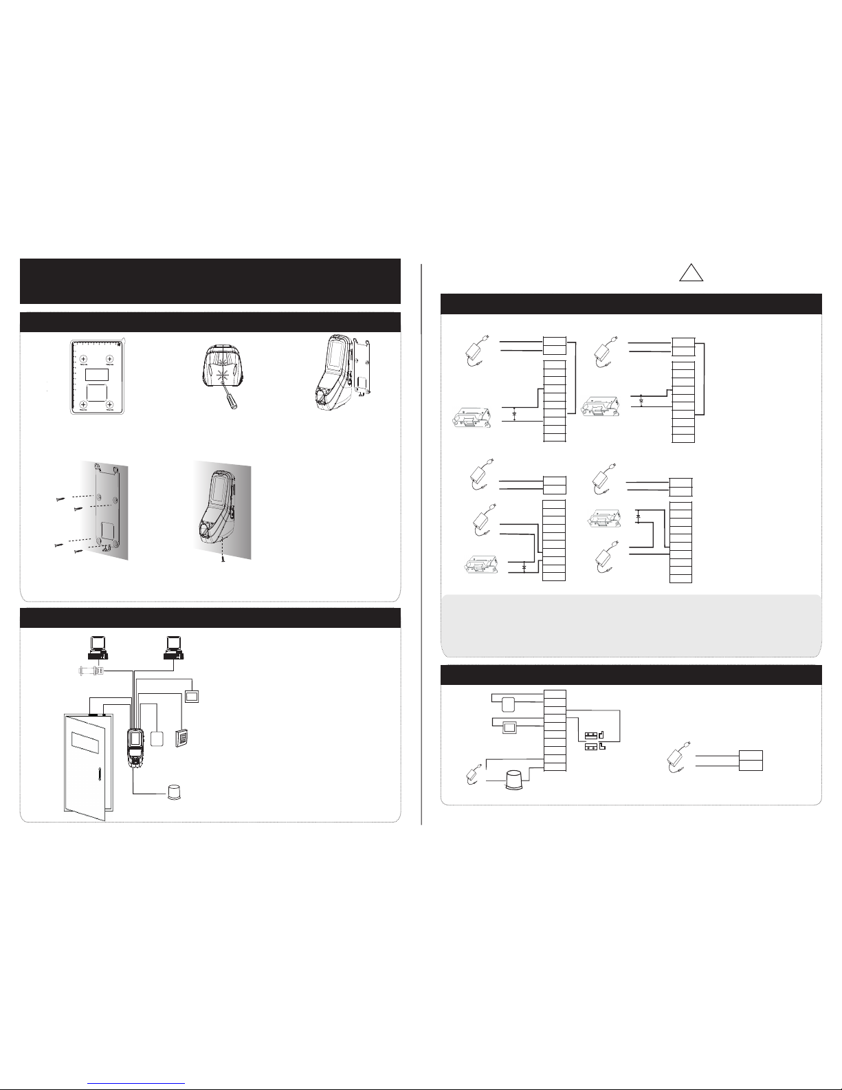
(1) Post the mounting template on the
wall.Drill the holes according to
the marks on the template (holes
Version: V1.0 Date: October 2010
(2) Remove the screw on the bottom
(3) Take away the back plate.
(5) Fix the device to the back plate.
acc ordin g to the mo untin g paper .
(4) F ix the ba ck plat e on the wa ll
RS485
TCP/IP
Lock
Sensor
①
③
Alarm
RS232/RS485 Converter
②
NC LOCK
-
+
DC12V
+
NC LOCK
+
-
NO LOCK
-
-
FR 107
+
-
FR 107
+12V
+12V
+12V
+12V
GND
GND
GND
GND
NC
NC
NC
NC
NC
NO
NO
NO
NO
NO
GND
GND
GND
GND
GND
COM
COM
COM
COM
COM
AL-
AL-
AL-
AL-
AL-
AL+
AL+
AL+
AL+
AL+
SEN
SEN
SEN
SEN
SEN
BUT
BUT
BUT
BUT
BUT
BELL+
BELL+
BELL+
BELL+
BELL+
BEL L-
BEL L-
BEL L-
BEL L-
BEL L-
NO LOCK
-
+
DC12V
+
-
+
-
FR 107
-
+
DC12V
+
-
-
+
DC power
-
+
DC12V
-
+
DC power
+
-
FR 107
+
DC12V
-
+
GND
+12V
Exit Button
⑤
External Reader
④
Door Bell
Door Bell
%
%
BUTTON
EXIT
EXIT
BUTTON
⑦
⑥
-
+
Alarm
Alarm Power
Exit Button
Door Sensor
MultiBio 7 00
(only for yo ur refe rence )
Mounting P aper
10
11
12
Wiring Hole
Instruction for the Mo unti ng Paper
Before the device is fas tene d, pleas e
stick the paper to the pla ce whe re you
want to install it, then m ake ho les and
lay cables according t o the mo unting
paper.
for screw and wiring).
of device.
Access Control System Function
(1) If a registered user verified, the device will export the signal
to unlock the door.
(3) If only the d llegal removed, the device will evice being i ly
(4) is External card reader supported.
(5) is it is External exit button supported, convenient to open the
export alarm signal.
door inside.
(7) Supports , modes with RS485 TCP/IP to connect PC. One PC can
manage multiple devices.
(6) External door bell is supported.
①: ‘‘I’: device output current, ‘ ’: lock voltage, ’: lock currentULOCK ILOCK
(1) The system supports NO LOCK and NC LOCK. For example the NO LOCK (normally open at power on) is connected
with ’NO’ terminal, and the NC LOCK is connected with ‘NC’ terminal.
(eq uippe d in the pa ckage ) to prev ent the s elf-i nduct ance EM F affect t he syst em, do no t rever se the po larit ies.
3.Lock Connection
!
Warning: No operating with power on
(1) Share power with the lock:
A. ULOCK=12V, I-ILOCK>1A…… ①
B. The lock is near to the device.
Device share power with the lock:
Device does not share power with the lock:
A. =12V I- ≤1A;ULOCK ILOCK
B ≠12V; . ULOCK
C. The lock is far apart from the device.
Voltage output ≤ DC 12V for Alarm
4. Other Parts Connection:
5. Power Connection:
Input DC 12V, 500mA (50mA standby)
Positive is connected with ‘+12V’, negative is connected
with ’GND’ (do not reverse the polarities).
(2) Does not share power with the lock:
2. Structure and Function
(2) D oor sen sor wil l detec t the on- off stat e. If the d oor is un -
exp ected o pened o r impro perly c losed , the ala rm sign al
(di gital v alue) w ill be tr igger ed.
MultiBio 700 Installa tio n Gui de
1. Equipment Instal lat ion
(2) W hen the E lectr ical Lo ck is conn ected t o the Acce ss Cont rol Sys tem, yo u need to p arall el one FR 107 dio de
Page 2
DATA1
DATA0
GND
+12V
GLED
RLED
BEEP
485+
485-
TXD
RXD
GND
GND
WD 0
WD 1
DATA0
GND
DATA1
Access Control
IWD1
12Vout
BEEP
GLED
RLED
IWD0
GND
IP Address:192.168.1.100
Subnet Mask:255.255.255.0
IP Address:192.168.1.124
Subnet Mask:255.255.255.0
Switch
PC
…
Side View Back View
Tamper Switch
Reset Button
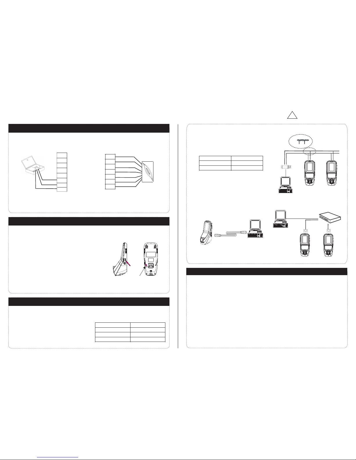
(1) RS232 Mode:
Terminals:
RXD Pin3-Txd
TXD Pin2-Rxd
GND Pin5-Gnd
485+ RS485+
485- RS485-
485+
485-
485+ 485-
RS485 Bus
485+ 485- 485+ 485-
RS485
10. Cautions:
6. Wiegand Output
The device supports standard Wiegand 26 output,
so you can connect it with most of the access control
7. Wiegand Input
connect with card reader. Theyan independent are installed each
The device has the function of Wiegand input upports to signal . It s
Wiegand signal extender in long distance or interference environment).
(2) To keep the stability of Wiegand signal, connect the device and the Access Control or Card Reader in same ‘GND’
(1) Please keep the distance between the device and Access Control or Card Reader less than 90 meters(Please use
There are three modes that the PC software communicate
and TCP/IP, and the last two modes support remote control.
9. Communication
8.Other Functions
(1) Manual Reset:
(2) R estor e Facto ry Sett ings:
(A) Crossover cable: The device and PC connected
(B) Straight cable: The device and PC connected to
(3) TCP/IP Mode:
(2) RS485 Mode:
etc . More in forma tion pl ease re fer to th e user ma nual.
Operation: Press the tamper switch three times after the alarm being
You can u se the ta mper sw itch to r estor e facto ry sett ings, s uch
Not e: The us er data w on’t be c leared .
other restart it.abnormality, you can use ‘Reset’ function to
hole with than 2mm).a sharp tool (the tip diameter less
Operation: Remove the black rubber cap, then stick the Reset button
If the device does not work properly because of misoperation or
as de vice nu mber, sy stem pa sswor d, IP addr ess, RS 485 add ress,
triggered 30 seconds but no more than 60 seconds.
Terminals PC Serial Ports
(2)We recommend the 3A/12V DC Power supply. Please contact our technical staff for details.
(5)Please connect the ‘GND’ before all the other wiring especially under the environment with much electrostatic.
( )3 Please read carefully the terminal description and wiring by rule strictly. Any damage caused by improper
(4)Keep the exposed part of wire less than 5mm, to avoid unexpected connection.
(6)Do not change the cable type because of long distance between the power and the device.
(1)Power cable is connected after all the other wiring. If the device is working abnormally, please shut down the power
first, then make the necessary check . Kindly reminds you that any hot-plugging may damage the device, and
operations will be out of the range of our guarantee.
it is not included in the warranty.
Terminals PC Serial Ports
Converter
!
Warning: No operating with power on
in any case.
sid e of the do or, to con trol th e lock an d acces s toget her.
Please use specified RS485 wire, RS485 active converter and
bus-type wiring.
and exchange information with the device: RS232, RS485
Terminals:
LAN/WAN through switch/Lanswitch.
directly.
(7) Please use specified RS485 wire, RS485 active converter and bus-type wiring.
devices by now.
 Loading...