

Zk software C3-100 Installation Instructions And Connection Manual
Key hole
Thread hole
Thread hole
3.Get through the thread hole
Get through the thread hole
Fixed case
1
2
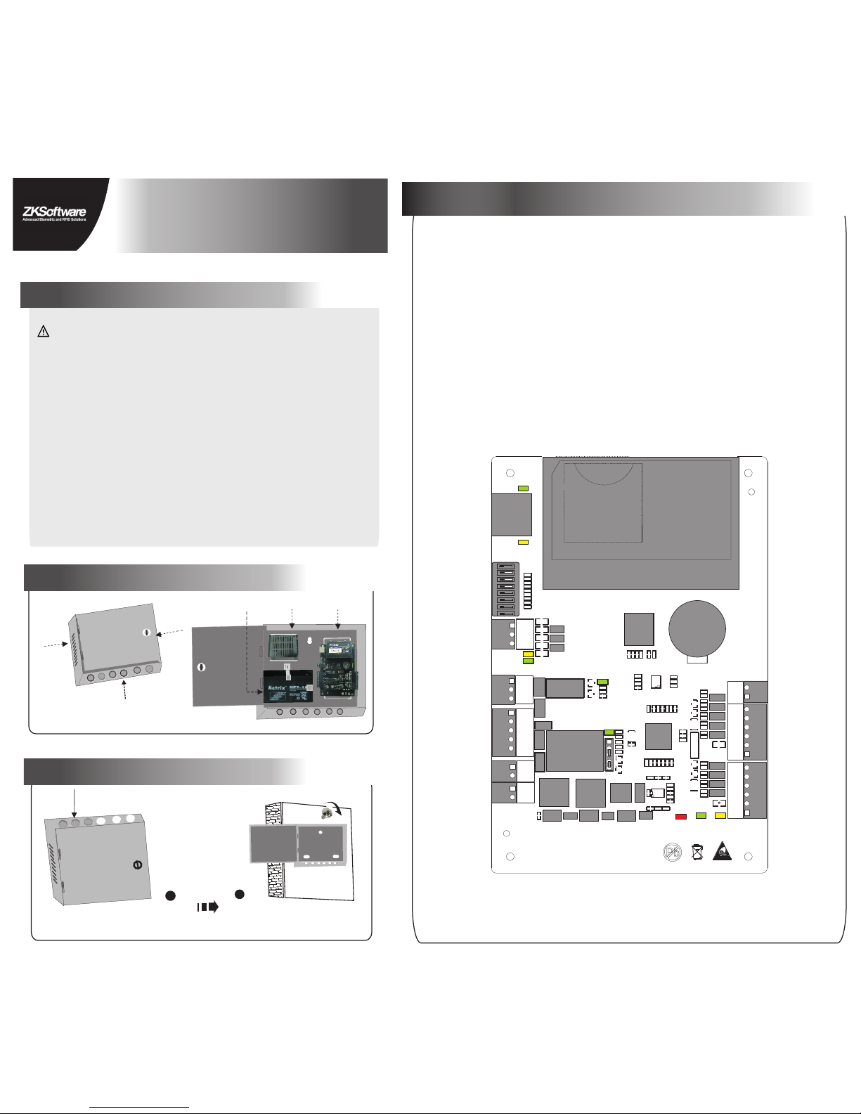
4.LED indicators, Wires, Auxiliary Input and Output
Appearance of case
Notes:
C3- 1 0 0 Installation Instructions and Connection Guide
1.Cautions
Ple ase not e the fol lowin g cauti ons.M is-op erati on may le ad to per sonal i njury o r equip ment fa ilure :
1) Do no t energ ize the sy stem be fore in stall ation i s compl ete; ne ver car ry out in stall ation a ctivi ties wh en
Visi on: 1. 0. 1
Dat e:Oc t. 2010
2) All p eriph eral de vices m ust be gr ounde d.
3) It is p refer red tha t all wir es run th rough P VC or gal vaniz ed pipe s.
5) It is r ecomm ended t hat car d reade rs and bu ttons s hould b e insta lled at h eight o f 1.4m- 1.5m ab ove gro und.
6) It is r ecomm ended t o use the p ower su pply in c ase for c ontro l panel , and ext ernal p ower su pply fo r each
4) It is s trong ly reco mmend ed that t he leng th of exp osed pa rt of any c onnec tion ca ble sho uld not b e longe r
Pro fessi onal cl ampin g tools m ay be use d to avoi d unint entio nal con tact of e xpose d wires t o tha n 4 mm.
the s ystem i s energi zed.
sho rt-ci rcuit o r commu nicat ion fai lure. avo id
Des cript ion of no rmal wo rking s tate:
Con nect th e syste m to the po wer sup ply.If t he syst em work s prope rly,the P OWER in dicat or(re d) is lit
con stant ly and th e RUN ind icato r(gre en) fla shes.
Hea t
dis sipat ion
hol e
2.Components
Power supply
Backup battery
Control panel
1)Meaning of LED indicators:
LINK indicator(green): always(green) indicates TCP/IP
ACT indicator(yellow):its flashing indicates data is in transmitting
TX indicator(yellow):its flashing indicates it is sending data through
RX indicator(green):its flashing indicates it is receiving data through
Auxiliary output indicator(green):always(green) indicates it is in use.
Lock indicator(green):always(green) indicates lock is open.
POWER indicator(red): always(red) indicates control panel is power
RUN indicator(green):its flashing indicates the system works normally.
CARD indicator(yellow):its flashing indicates card is punched on reader.
A Use 2-conducotor power cord
2)Recommended use of wires:
3)The auxiliary input may be connnected to infrared body detectors,
4)The auxiliary output may be connected to door bells,alarms,etc.
B Use 6-conductor wire between wiegand reader and control panal
C Use 4-conducotor lock power cord (RVV 4*0.75mm)
D Use 2-conducotor switch power cord(RVV 2*0.5mm)
communication is proper;
on.
alam switches,etc.
Ethernet interface
Dip switch
RS485 interface
Auxiliary output1
Door1
Power of lock
Power of control panel
A
A
C
D
D
B
B
{
{
{
{
{
BUTTON1
READER1 READER2
+12V
+12V
GND
GND
WD1
WD1
WD0
WD0
GLED
GLED
BEEP
BEEP
IN
GND
ACT
LINK
1
TX
RX
V+
POWER
PC
NC
COM
NO
COM
NO
NC
LOCK1
GND
SEN
V-
GND
485-
485+
AUXOUT1
LOCK
GND
+12V
1 2 3 4
ON
5 6 7 8
1
POWER
CARD
RUN
LAN
SD card
Advanced Access Control
loc k.
through TCP/IP communication.
RS485 communication.
RS485 communication.
(RVVP 6*0.5mm) (To choose the proper cord according to the
interface you connect, such as 6,8,10 cord.)
1# Door Button
1# Door
wiegand reader
1# Door
wiegand reader
BUTTON1
READER1 READER2
+12V
+12V
GND
GND
WD1
WD1
WD0
WD0
GLED
GLED
BEEP
BEEP
IN
GND
ACT
LINK
1
TX
RX
V+
POWER
PC
NC
COM
NO
COM
NO
NC
LOCK1
GND
SEN
V-
GND
485-
485+
AUXOUT1
LOCK
GND
+12V
1 2 3 4
ON
5 6 7 8
1
POWER
CARD
RUN
LAN
SD卡
Advanced Access Control
1 2 3 4
1 2 3 4
ON
ON
5 6 7 8
5 6 7 8
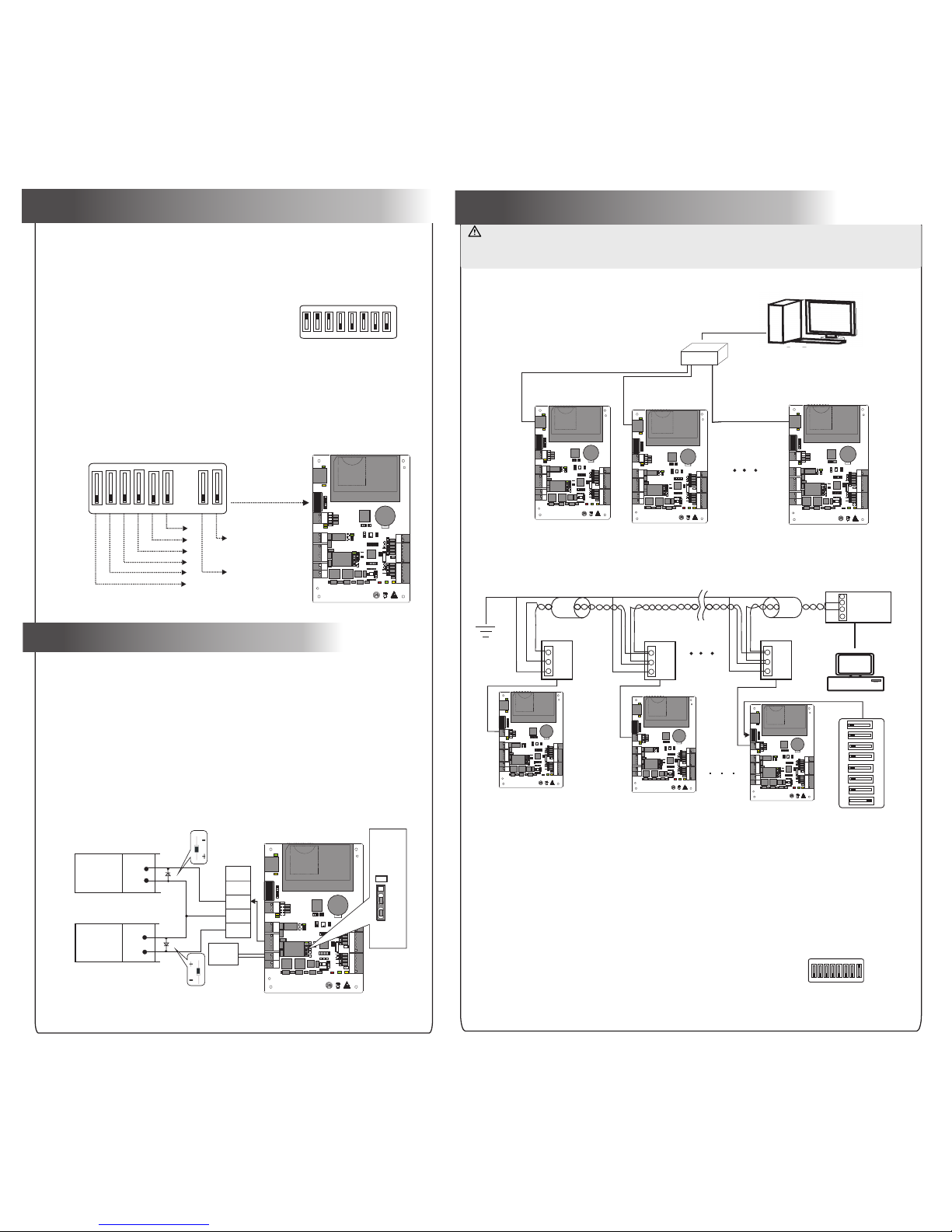
Dia gram of p laces o f DIP swit ch.
1
2
4
8
16
32
Res tore
fac tory se tting .
RS4 85
ter minal
res istan ce.
fig ure( 5- 1)
Set R S485 ad dress t hroug h DIP swit ch:
1)Internationally accepted RVSP(shielded twisted-pair) wires should be used for communication to effectively avoid interference.
RS485 communication wires should be connected by means
of bus cascade connection.
2.RS485 Communication
1.TCP/IP Communication
The background PC software is able to communicate with the system according to two protocols(RS485 and TCP/IP) for data
exchange and remote management. The communication cable should be away from high-voltage lines as far as possible. Do
not keep the communication cable in parallel with power cords or bind them together.
3)One RS485 BUS may hold 63 units of control panel, but it is not recommended to connect with more than 32 units.
access control panels.
7.Equipment communication
5.RS485 address setting, Restore factory setting, Terminal resistance setting
NO Lock
NC Lock
+
+
+
-
-
Lock p ower
inpu t
Enla rged di agram
of loc k ports
NC
NO
GND
COM
SEN
Diode
Diode
LOCK
LOCK
+
+
-
-
FR107
FR107
6.Connection of lock
“Wet mode” wiring diagram of lock connecting with external power supply.
-
LED
1
2
3
4
5
Jum per
ter minal
Fac tory
def ault
wet m ode
1 2 3 4 5 6 7 8
ON
Not es:
4) When t he bus is l onger t han 300 m, to enh ance th e stabi lity of c ommun icati on, it is n ecess ary to ke ep plac e 8 of DIP
2) Cons ideri ng stab ility o f commu nicat ion, it i s recom mende d the len gth of RS 485 bus i s less th an 600m
As sh own in th e figur e above , place 8 o f the DIP sw itche s of unit s 1# and 8# i s place d at "ON " s tatus .
PC
Swi tch
DIP s witch
1 2 3 4
ON
5 6 7 8
1# co ntrol p anel 2# co ntrol p anel
8# co ntrol p anel
485+
485-
GND
48 5
Con verte r
485+
485+
485+
485-
485-
485-
GND
GND
GND
ser ial lin e
PC
3) Wh en the Ele ctric al Lock i s conne cted to t he Acces s Contr ol Syst em, you n eed to pa ralle l one FR1 07
in th e packa ge) to pr event t he self -indu ctanc e EMF affe cting t he syst em, do no t rever se dio de (equ ipped
the p olari ties.
1# co ntrol p anel
2# co ntrol p anel
n# co ntrol p anel
BUTTON1
READER1 READER2
+12V
+12V
GND
GND
WD1
WD1
WD0
WD0
GLED
GLED
BEEP
BEEP
IN
GND
ACT
LINK
1
TX
RX
V+
POWER
PC
NC
COM
NO
COM
NO
NC
LOCK1
GND
SEN
V-
GND
485-
485+
AUXOUT1
LOCK
GND
+12V
1 2 3 4
ON
5 6 7 8
1
POWER
CARD
RUN
LAN
SD卡
Advanced Access Control
BUTTON1
READER1 READER2
+12V
+12V
GND
GND
WD1
WD1
WD0
WD0
GLED
GLED
BEEP
BEEP
IN
GND
ACT
LINK
1
TX
RX
V+
POWER
PC
NC
COM
NO
COM
NO
NC
LOCK1
GND
SEN
V-
GND
485-
485+
AUXOUT1
LOCK
GND
+12V
1 2 3 4
ON
5 6 7 8
1
POWER
CARD
RUN
LAN
SD卡
Advanced Access Control
BUTTON1
READER1 READER2
+12V
+12V
GND
GND
WD1
WD1
WD0
WD0
GLED
GLED
BEEP
BEEP
IN
GND
ACT
LINK
1
TX
RX
V+
POWER
PC
NC
COM
NO
COM
NO
NC
LOCK1
GND
SEN
V-
GND
485-
485+
AUXOUT1
LOCK
GND
+12V
1 2 3 4
ON
5 6 7 8
1
POWER
CARD
RUN
LAN
SD卡
Advanced Access Control
BUTTON1
READER1 READER2
+12V
+12V
GND
GND
WD1
WD1
WD0
WD0
GLED
GLED
BEEP
BEEP
IN
GND
ACT
LINK
1
TX
RX
V+
POWER
PC
NC
COM
NO
COM
NO
NC
LOCK1
GND
SEN
V-
GND
485-
485+
AUXOUT1
LOCK
GND
+12V
1 2 3 4
ON
5 6 7 8
1
POWER
CARD
RUN
LAN
SD卡
Advanced Access Control
BUTTON1
READER1 READER2
+12V
+12V
GND
GND
WD1
WD1
WD0
WD0
GLED
GLED
BEEP
BEEP
IN
GND
ACT
LINK
1
TX
RX
V+
POWER
PC
NC
COM
NO
COM
NO
NC
LOCK1
GND
SEN
V-
GND
485-
485+
AUXOUT1
LOCK
GND
+12V
1 2 3 4
ON
5 6 7 8
1
POWER
CARD
RUN
LAN
SD卡
Advanced Access Control
BUTTON1
READER1 READER2
+12V
+12V
GND
GND
WD1
WD1
WD0
WD0
GLED
GLED
BEEP
BEEP
IN
GND
ACT
LINK
1
TX
RX
V+
POWER
PC
NC
COM
NO
COM
NO
NC
LOCK1
GND
SEN
V-
GND
485-
485+
AUXOUT1
LOCK
GND
+12V
1 2 3 4
ON
5 6 7 8
1
POWER
CARD
RUN
LAN
SD卡
Advanced Access Control
BUTTON1
READER1 READER2
+12V
+12V
GND
GND
WD1
WD1
WD0
WD0
GLED
GLED
BEEP
BEEP
IN
GND
ACT
LINK
1
TX
RX
V+
POWER
PC
NC
COM
NO
COM
NO
NC
LOCK1
GND
SEN
V-
GND
485-
485+
AUXOUT1
LOCK
GND
+12V
1 2 3 4
ON
5 6 7 8
1
POWER
CARD
RUN
LAN
SD卡
Advanced Access Control
1) Pl ace 1-6 o n DIP swit ch are fo r setti ng the nu mber of c ontro l panel w hen com munic ating t hroug h
RS4 85, it is a dopte d for bin ary cod ing, an d littl e endia n, the ad dress r epres ented b y place 1 -6 are
sho wn as fig urue( 5-1).
2) Be fore se tting t he addr ess, pl ease ke ep the sy stem is p ower off , Jump pl ace 1-6 t o desir ed stat us,
and t he addr ess num ber sha ll not be t he same a s anoth er one in t he netw ork. Fo r examp le: to se t the
dev ice num ber as 39 ( 39=1+ 2+4+3 2), the c orres pondi ng RS48 5 code is 111 001, th en Jump p lace 1,
2,3 a nd 6 at “ON ” statu s.
3) Pl ace 7 is fo r resto ring fa ctory d efaul t setti ngs, Ju mp it for t hree ti mes wit hin 10 se conds a nd rest art
the s ystem , then al l infor matio n in RAM of c ontro l panel w ill be cl eared a nd the sy stem re store s facto ry
def ault se tting s.
4) Pl ace 8 is fo r setti ng term inal re sista nce whe n commu nicat ing thr ough RS 485. Ju mp it at “O N” stat us,
the n it is equ ivale nt to hav e a termi nal res istan ce of 120 o hm betw een 485 + and 485 -.
1) Co ntrol p anel pr ovide s lock co ntrol o utput i nterf aces. F or NO loc k ,it is op en when p ower is o n, and
clo sed whe n power i s off, so “ COM and N O” inter faces s hould b e used; F or NC loc k, it is op en when
pow er is off , and clo sed when p ower is o n, so CO M and NC” in terfa ces sho uld be us ed.
2) Co ntrol p anel su pport s “dry mo de” and “ wet mod e” by set ting th e jumpe r, it is “we t mode” w hen
con necti ng “V+ V-” In put int erfac es to sup ply pow er for lo cks, pl ease sh orten 2 -3 and 4- 5. Equi pment
fac tory de fault s ettin g is dry mo de. For s ettin g “dry mo de” and “ wet mod e”, ple ase ref er to <<C 3-100 /
200 /400 ac cess co ntrol p anel in stall ation i nstru ction s>>.
swi tches o f the fir st and th e last co ntrol p anel at “ ON” sta tus.
 Loading...