

Page 1

Installation Instruction
Version: 1.1
PL10R/ML10R
Page 2

A
B
C
C
D
E
F
I
H
G
K
J
L
M
N
Before Installation
Diagram
1
Page 3

64mm 72mm
35mm 40mm
30mm 35mm
Mounting Hardware Package Mounting Hardware Package
for door thickness of 39-46mm for door thickness of 47-54mm
A
H
E
L
M
J
H
E
L
M
J
G
O
F
K
B
D
N
C
I
Packing List
2
Page 4
Note: The stand ard lock includ es 2 mounting ha rd ware packa ges only, which are used for th e door
thickn ess of 39-46mm a nd 47-54 mm sepa rately.
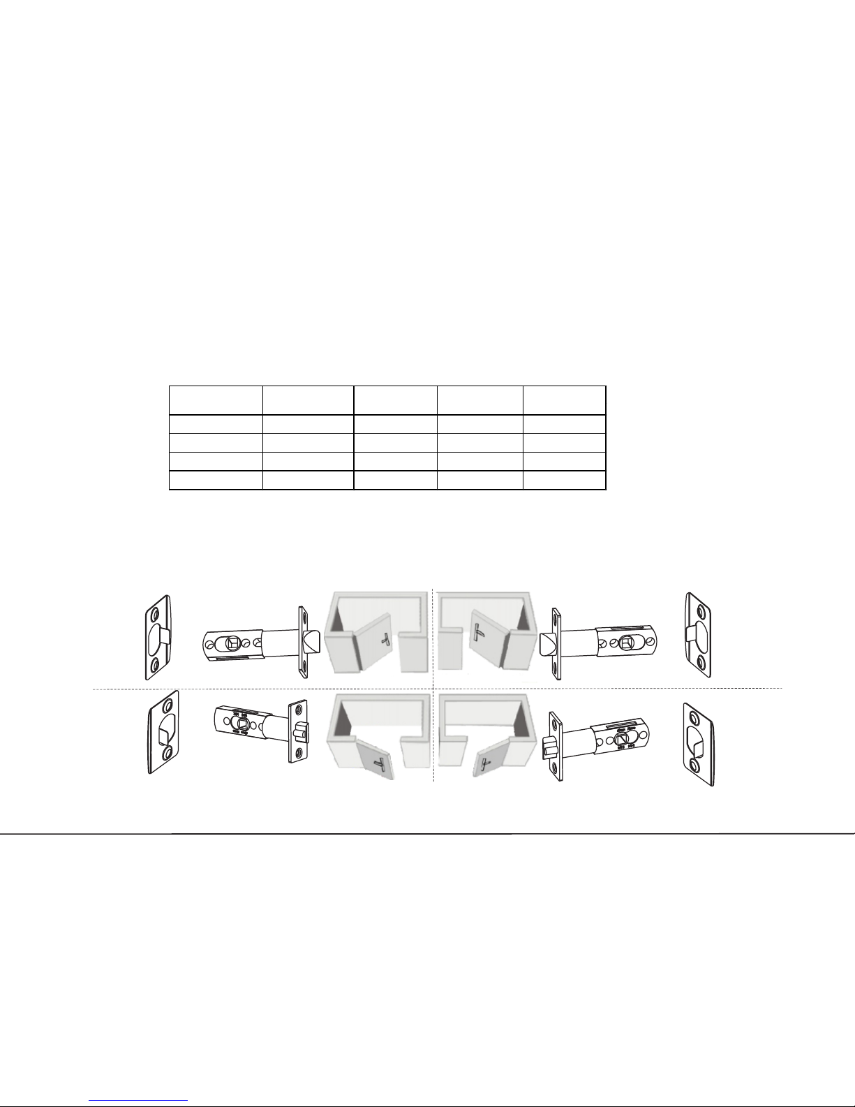
Note: Please refer to the above p icture to adjus t the direction of strike plate F and latch D.
1. Check the door thickness and prepare the corresponding mounting
hardware package.
2. Check door opening direction.
F
F
F
F
D
D
D
D
30~38 56 20 10 25
39~46 64 30 10 35
47~54 72 35 10 40
55~60 80 45 10 50
M Screw Length
(mm)
L Screw Length
(mm)
Door Thickness
(mm)
H Spindle Length
(mm)
J Screw Length
(mm)
Lef t Inward Right inward
Lef t outward Right outward
Door Preparation
3
Page 5

70mm 60mm
3. Check the required backset (60mm or 70mm).
Note2: The latch has two backset options: 60mm and
70mm, please choose either one as required.
Note1: Installation template has the backset
options of both 60mm and 70mm.
4
Page 6

Hexagon Screw
1. New lock is configured to grant ANY Mifare card access to unlock.
2. The lock is equipped with mechanical keys for manual unlocking. Remove mechanical keys from the
package and keep them in a safe place.
3. To power up the lock, four alkaline AA batteries (not included) are required. Non-alkaline and
rechargeable batteries ARE NOT RECOMMENDED.
4. The operation of lock setting has a stand-by time limit of 10 seconds; if there is no any activity, the lock
will shut off after 10 seconds.
N
A
5
Remarks
How To Use Mechanical Key And Change Handle Direction?
Page 7
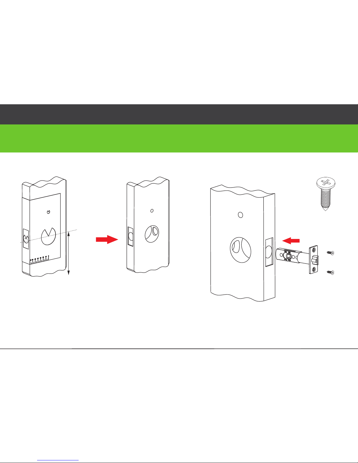
1. Align the templ ate along the ver tical ce nter line of
the latch(D) at the desired hand le height, and t ape it
to the door.
2. Mark the h oles first, an d then star t drillin g.
E
E
D
cente
r line of the
hand
l
e
d
esir
e
d h
and
le
h
ei
g
ht
1.Drill holes on the door. 2. Install the latch (D).
Installation
6
Page 8

Correct Position: T he small triangle
must be vertically upward.
This position is wrong .
B
H
C
3.Install outdoor unit(B) with gasket(C) and spindle(H) on the
door.
7
Page 9

J
M
Note : Push cable into the hole first.
L
B
C
I
I
C
J
4.Install mounting plate (I) with gasket (C) on the door.
5.Install indoor unit (K).
8
Page 10
(5/64")
14
mm
21 mm
2mm
K
E
G
F
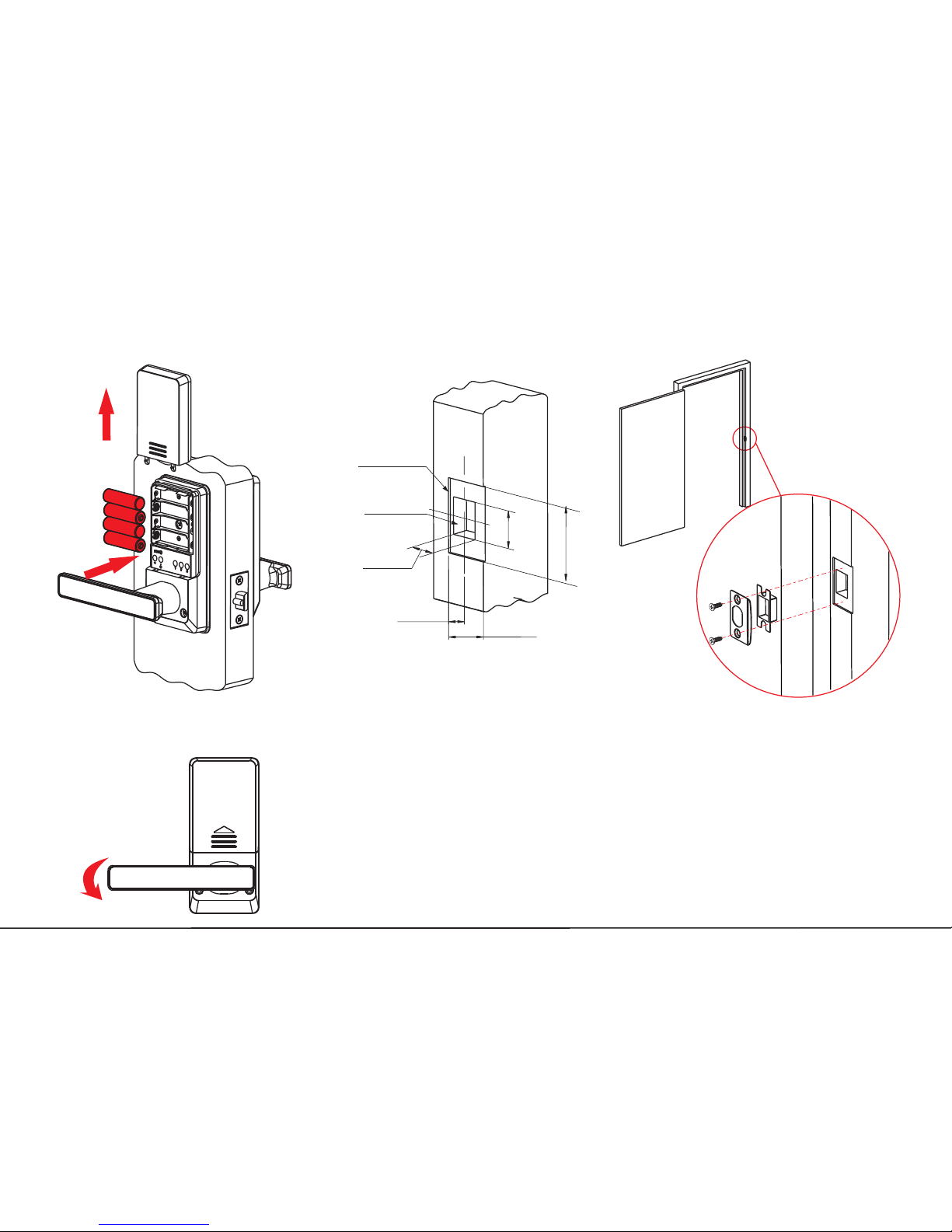
Note : When the door is l ocked and the clutch is idle, the front handle will be turned,
but the door will remain locked.
6.Insert batteries.
7.Mark and drill holes for the strike.
8. Test the lock by rotating the back handle and using the mechanical
key(A).
9
(15/32")
(53/64")
(35/64")
(1-3/8")
(1-9/64")
(2-9/32")
 Loading...