

Page 1

Installation Instruction
PL10/ML10
Version:1.0
Page 2

Before Installation
Diagram
B
C
C
K
L
J
M
1
N
I
H
D
E
F
A
G
Page 3
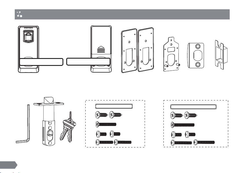
Packing List
C
H
E
L
M
J
I
F
G
A
K
Mounting Hardware Package Mounting Hardware Package
39-46mm door thickness 47-54mm door thickness
H
E
L
M
J
64mm 72mm
35mm 40mm
30mm 35mm
B
D
N
2
Page 4

Door Preparation
30~38 56 20 10 25
39~46 64 30 10 35
47~54 72 35 10 40
55~60 80 45 10 50
H Spindle Leng th
(mm)
J Scre w Length
(mm)
M Scr ew Len gth
(mm)
L Screw Le ngth
(mm)
Door Thickness
(mm)
1. Check door thickness and prepare the mounting hardware
package.
Not e: Th e s tan d ard lo c k inc l ude s 2 m oun t ing ha r dwa r e pac k age on ly, whi c h is us e d for th e
doo r thic k nes s o f 39- 4 6mm an d 4 7-5 4 m m sep a rat e ly.
2. Check door open direction.
F
D
D
F
F
3
Not e: Ple a se re f er th e a bove p ictu r e to ad j ust t h e dire c tio n o f str i ke pl a te F and l a tch D .
D
F
D
Page 5

3. Check the required backset (60mm or 70mm).
70m m 60mm
Note2:
Note1: Ins ta ll at io n te mp la te h as t he backset
options of b ot h 60 mm a nd 7 0m m.
4
The latch ha s TWO backset options:
60mm or 70mm , pl ea se a dj us t it b y yo ur se lf.
Page 6

Cautions
1. New lock is c on fi gu re d to g ra nt AN Y fi ng er pr in t ac ce ss t o un lock.
2. The l oc k is e quipped with me ch an ic al keys for m an ua l unlocking. Remo ve m ec ha nical keys
from the pac ka ge a nd k ee p th em i n a sa fe p la ce.
3. To power on the lock, four al ka li ne AA ba tt er ie s (not included) are required. Non- al ka li ne
and rechar ge ab le b at te ri es AR E NO T RE CO MM EN DE D.
4. Please avoid strong light direct to the f in gerprint holder, otherwise the inf ra red sen so r
might be dis tu rb ed .
5. The operati on of setting lock has a st an d- by time limit of 10 seconds; Without an y a ct iv it y,
lock will sh ut o ff after 10 seconds.
6. Keep your f in ge rs c le an w he n us in g this lock.
How To Use Mechanical Key And Change Handle Direction?
Hexagon Screw
N
A
5
Page 7

Installation
1.Drilling holes on the door. 2. Install the latch (D).
E
d h
he
le
le
and
cente r line of t
nd
ha
e
esir
d
ht
ig
e
h
1). Ali g n the t e mpl a te al o ng the v e rti c al ce n ter l i ne of
th e l atch ( D) at t h e des i red ha n dle h e igh t , and t a pe it
to t h e door.
2). Mark t h e hol e s fir s t, the n star t d ril l ing .
6
E
D
Page 8

3.Install outdoor unit(B) with gasket(C) and spindle(H) on the
door.
B
C
Correct Position: T he small triangle
must be vertically upward.
H
This position is Wrong !.
7
Page 9

4.Install mounting plate (I) with gasket (C) on the door.
J
I
5.Install indoor unit (K).
M
8
L
C
C
B
I
J
Note : Push cable into the hole at first.
Page 10

6.Install the battery.
K
7.Mark and drill holes for strike.
2mm
(5/64")
12mm
(15/32")
29(mm
21mm
(53/64")
14(mm
(35/64")
)
(1-9/64")
35(mm)
(1-3/8")
58(mm)
(2-9/32")
G
F
E
8. Testing the lock by rotating back handle and using
mechanical
key(A).
Note : W hen the door is l ocked, the clutch is in idle position, the
front handle will be turned. However, the door will remain locked.
9
 Loading...