

ZIVO Technologies ZTFDT433 User Manual
Manual
•
•
•
•
•
•
by Zivo Technologies™
The WellAWARE™ System is an eldercare tool for use by primary caregivers. It
consists of wireless sensors, a Data Manager and a login to the WellAWARE™ website. The
wireless sensors send data to the Data Manager which sends it along to the WellAWARE™
servers where it can be viewed in the form of reports by the caregivers. The reports consist
of things such as sleep quality, bathroom visits and general activity.
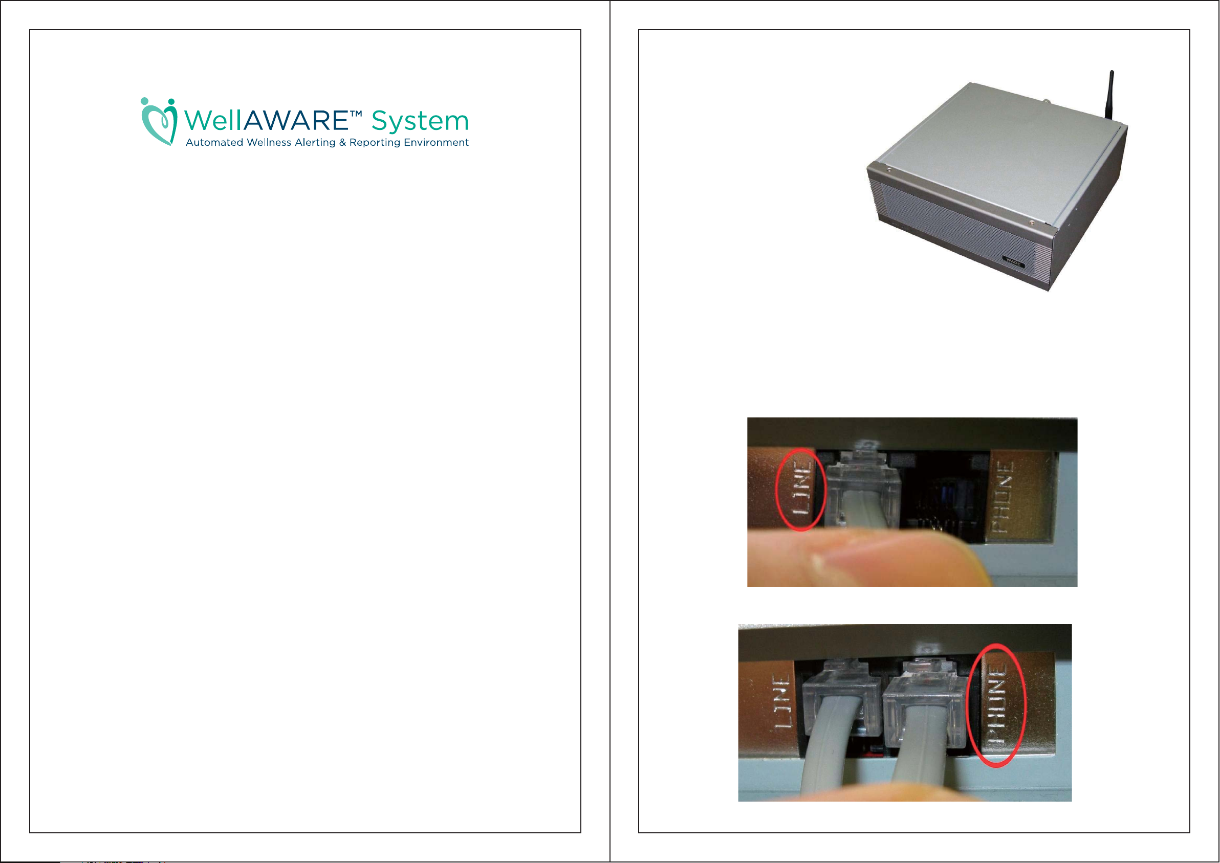
Data Manager
The Data Manager is the central piece of
equipment that sends all the data produced by
each sensor along to the WellAWARE™
server where it is presented to the
caregiver.
Installation:
The Data Manager should be
placed out of the way preferably out
of sight. The antenna needs to be
attached to the back via the small screw
RF connector. Plug in the included phone
cord into the wall at one end and the port labeled
‘Line’ on the back of the Logger. Next, plug in the
typical power brick and push the switch on the front to start it up.
That’s all it takes as the Data Manager will begin working immediately.
Considerations:
The WellAWARE™ system can use six different sensors to gather data. They are:
PIR Activity Detector (ZT-PIR433)
o For obtaining general activity data
Temperature/PIR Activity Detector (ZT-PTS433)
o For notification of dangerous temperature rises as well as general activity
Humidity/PIR Activity Detector (ZT-PHS433)
o For humidity rise detection and motion detection for shower confirmation.
Door/Window Sensor (ZT-DWS433)
o For sensing opening of doors and windows.
Fall Detector (ZT-FDT433)
o For sensing impact events such as potential falls.
Bedbox (ZT-BBX433)
o For reporting sleep quality.
Ensure there is adequate clearance (an inch or so) around the Data Manager. Do not lay
cloth or pillows on the Data Manager. Avoid placing the Data Manager in an area where pillows
or clothes will be laid on it. Other electronics such as a phone or radio may be placed on the
Data Manager if there are still large areas around the case where air can get through.
Make sure the phone cord from the wall is plugged into the line socket.
If there is a phone it should be plugged into the socket labeled phone.
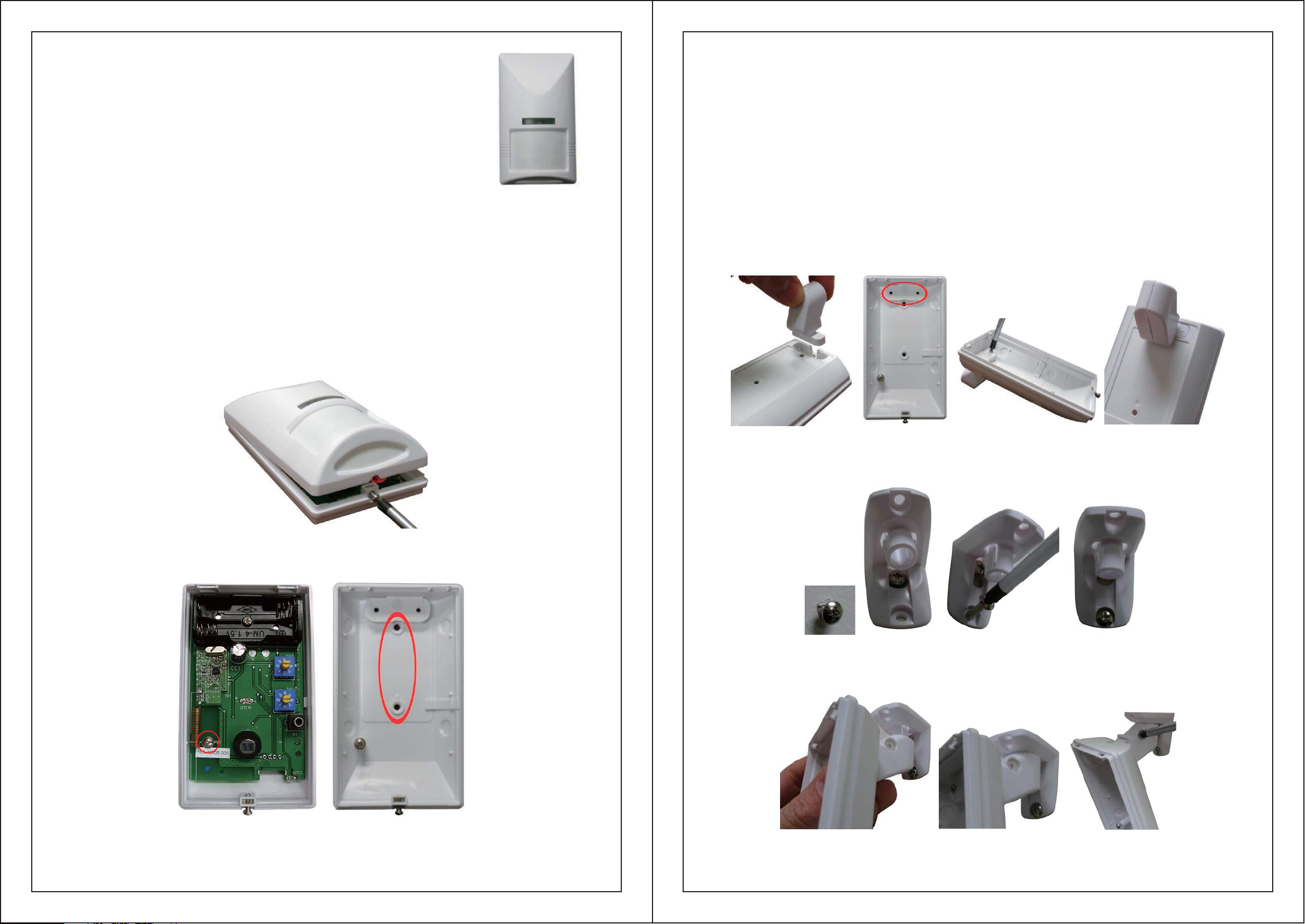
PIR Activity Detector
The Motion Sensors are the most basic sensor in the WellAWARE™
system. Motion Sensors simple report to the Data Manager when motion is
detected in the vicinity. Each one is mapped to a room or area such as Living
Room or Bathroom.
Installation:
Each Motion Sensor takes 2 AAA batteries. The Motion Sensor can either be mounted directly
to the wall or using the swivel mount to place it at useful angles.
To mount the motion detector directly to the wall:
The cover for the Motion Detector is secured with a single screw at the bottom. Unscrew
this and the cover should pivot up and come off easily. Locate the small screw inside the Motion
Detector on the left side. Loosen the screw by turning it counterclockwise until the circuit board
can slide down. The board should then be carefully lifted out. The included screws can then be
used in the holes provided on the back of the Motion Detector indicated below. Carefully
replace the circuit board and secure into place by tightening the screw at the correct line (WHAT
ARE THE +3, PET, -1, AND -2) then attach the cover. Be sure to install the batteries before
closing the case.
If you are using the swivel mount for the Motion Detector:
Open the Motion Detector up as described above. If you haven’t already done so, you should
separate the swivel mount into two pieces. The top piece (the one with the flat edges that go
against the wall or ceiling) should be separated from the bottom piece (the one with the nylon
screw in it). Insert the bottom part of the swivel mount into the depression at the top of the back
of the Motion Detector. The screws included in the swivel mount can then be screwed into the
mount from the inside of the Motion Detector. The included wall mount screws can then be used
to screw the top part of the mount to the wall before clicking the bottom part (with the motion
detector already attached) to it. If you’re mounting the swivel to a wall you’ll need to first screw
in the top screw then hang the top part of the swivel mount on that screw as shown below then
screw in the bottom screw so the apparatus is secure. For a ceiling mount, both screws are put in
through the holes. The motion sensor can then be put in the proper orientation. The nylon screw
will hold the sensor at a preferred vertical angle. It will not have an effect on the left to right angle.
Open the case using a screwdriver to loosen the screw at the bottom, then lift the top off.
Place the bottom part of the swivel mount in the recessed back then drive the two small
included screws to affix it to the back securely.
To affix the top part to the wall first drive a screw in then slide the swivel mount top onto it
and drive the bottom screw in tight.
The screw indicated on the left must be loosened then the PCB can be slid down and lifted
up. Underneath is the holes used for mounting indicated by the red circle.
Next push the bottom part up onto the top part till it clicks. Finally adjust the direction
and angle and tighten the nylon screw.
 Loading...