

Manual
•
•
•
•
•
•
by Zivo Technologies™
The WellAWARE™ System is an eldercare tool for use by primary caregivers. It
consists of wireless sensors, a Data Manager and a login to the WellAWARE™ website. The
wireless sensors send data to the Data Manager which sends it along to the WellAWARE™
servers where it can be viewed in the form of reports by the caregivers. The reports consist
of things such as sleep quality, bathroom visits and general activity.
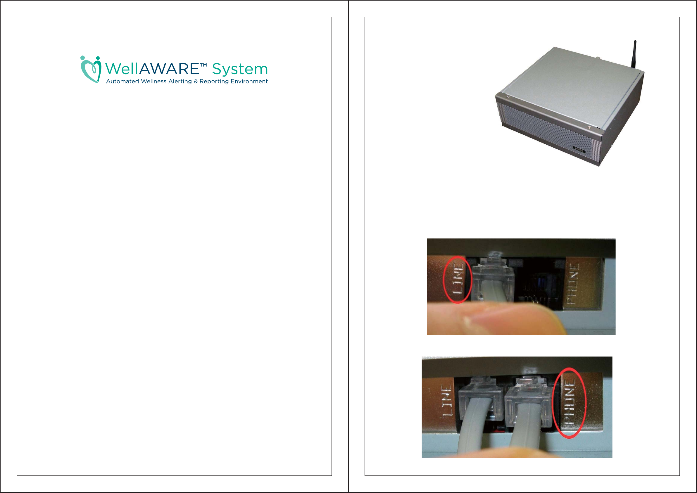
Data Manager
The Data Manager is the central piece of
equipment that sends all the data produced by
each sensor along to the WellAWARE™
server where it is presented to the
caregiver.
Installation:
The Data Manager should be
placed out of the way preferably out
of sight. The antenna needs to be
attached to the back via the small screw
RF connector. Plug in the included phone
cord into the wall at one end and the port labeled
‘Line’ on the back of the Logger. Next, plug in the
typical power brick and push the switch on the front to start it up.
That’s all it takes as the Data Manager will begin working immediately.
Considerations:
The WellAWARE™ system can use six different sensors to gather data. They are:
PIR Activity Detector (ZT-PIR433)
o For obtaining general activity data
Temperature/PIR Activity Detector (ZT-PTS433)
o For notification of dangerous temperature rises as well as general activity
Humidity/PIR Activity Detector (ZT-PHS433)
o For humidity rise detection and motion detection for shower confirmation.
Door/Window Sensor (ZT-DWS433)
o For sensing opening of doors and windows.
Fall Detector (ZT-FDT433)
o For sensing impact events such as potential falls.
Bedbox (ZT-BBX433)
o For reporting sleep quality.
Ensure there is adequate clearance (an inch or so) around the Data Manager. Do not lay
cloth or pillows on the Data Manager. Avoid placing the Data Manager in an area where pillows
or clothes will be laid on it. Other electronics such as a phone or radio may be placed on the
Data Manager if there are still large areas around the case where air can get through.
Make sure the phone cord from the wall is plugged into the line socket.
If there is a phone it should be plugged into the socket labeled phone.
PIR Activity Detector
The Motion Sensors are the most basic sensor in the WellAWARE™
system. Motion Sensors simple report to the Data Manager when motion is
detected in the vicinity. Each one is mapped to a room or area such as Living
Room or Bathroom.
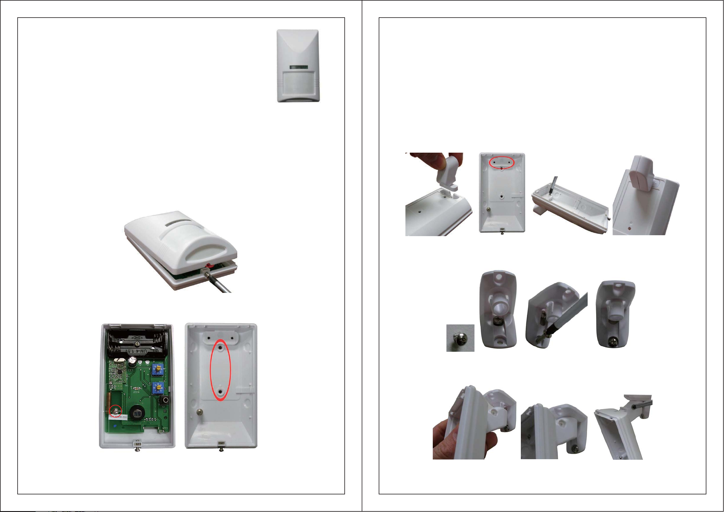
Installation:
Each Motion Sensor takes 2 AAA batteries. The Motion Sensor can either be mounted directly
to the wall or using the swivel mount to place it at useful angles.
To mount the motion detector directly to the wall:
The cover for the Motion Detector is secured with a single screw at the bottom. Unscrew
this and the cover should pivot up and come off easily. Locate the small screw inside the Motion
Detector on the left side. Loosen the screw by turning it counterclockwise until the circuit board
can slide down. The board should then be carefully lifted out. The included screws can then be
used in the holes provided on the back of the Motion Detector indicated below. Carefully
replace the circuit board and secure into place by tightening the screw at the correct line (WHAT
ARE THE +3, PET, -1, AND -2) then attach the cover. Be sure to install the batteries before
closing the case.
If you are using the swivel mount for the Motion Detector:
Open the Motion Detector up as described above. If you haven’t already done so, you should
separate the swivel mount into two pieces. The top piece (the one with the flat edges that go
against the wall or ceiling) should be separated from the bottom piece (the one with the nylon
screw in it). Insert the bottom part of the swivel mount into the depression at the top of the back
of the Motion Detector. The screws included in the swivel mount can then be screwed into the
mount from the inside of the Motion Detector. The included wall mount screws can then be used
to screw the top part of the mount to the wall before clicking the bottom part (with the motion
detector already attached) to it. If you’re mounting the swivel to a wall you’ll need to first screw
in the top screw then hang the top part of the swivel mount on that screw as shown below then
screw in the bottom screw so the apparatus is secure. For a ceiling mount, both screws are put in
through the holes. The motion sensor can then be put in the proper orientation. The nylon screw
will hold the sensor at a preferred vertical angle. It will not have an effect on the left to right angle.
Open the case using a screwdriver to loosen the screw at the bottom, then lift the top off.
Place the bottom part of the swivel mount in the recessed back then drive the two small
included screws to affix it to the back securely.
To affix the top part to the wall first drive a screw in then slide the swivel mount top onto it
and drive the bottom screw in tight.
The screw indicated on the left must be loosened then the PCB can be slid down and lifted
up. Underneath is the holes used for mounting indicated by the red circle.
Next push the bottom part up onto the top part till it clicks. Finally adjust the direction
and angle and tighten the nylon screw.

Considerations when placing Motion Sensors:
Use both screws for mounting. The increased stability will make replacing the batteries
later much easier. The nylon screw does not need to be very tight, once it stops test the vertical
angle if it’s secure you don’t need to tighten it anymore.
The Motion Sensors should be placed so they can ‘see’ only the room or area they are
mapped for. Each motion sensor has a range of over 15ft that is angled down. Place the Motion
sensors so they will only be triggered when the resident is in the designated area. While it is not
always possible to make only one motion sensor be triggered at a time it is important that the
bedroom motion sensor and to a lesser extent the bathroom motion sensor is isolated. This
means for example that no other motion sensors other than the one mapped Bedroom should be
triggered when anyone is in the bedroom.
Motion Sensors should be placed so all areas are covered. If a person is in the home he
or she should be in the range of a Motion Sensor.
Temperature/Humidity/PIR Activity Detector
The Motion Detector with a temperature or humidity sensor on it is very similar to just
the Motion Detector alone. These sense when motion is detected in the vicinity as well as
whether or not a rise in humidity or temperature has been detected. The Temperature Motion
Sensor is usually mapped to the Kitchen and the Humidity Motion Sensor is usually mapped to
the Shower.
Door/Window Sensor
The Door Window Sensor signals the Data Manager when a door or window is opened or
closed. This sensor is usually mapped to the entryway. So the sensor will be mounted on any
doors used to enter or exit the home. The sensor is triggered when the magnet part (smaller
magnetic white part) is either placed close to the left side of the sensor where the small triangle is
or moved away from this area.
Installation:
The Door Window Sensor is held together by a plastic tab as shown. Push the tab in and
pull to open the case. The sensor takes two AAA batteries. It can be mounted using the screw
holes indicated below. Mount the sensor and the magnet part so the magnet part is close to the
left side of the sensor where the small triangle is when the door is closed.
Installation:
Please refer to Motion Sensors for installation instructions. However there are some
considerations when dealing with the Temperature or Humidity versions.
Considerations:
The Temperature Motion Sensor should be placed as close to a working stove as possible.
It should still cover the majority of the kitchen (where it will usually be placed) though. If the
stove is not in use this is not required. The Humidity Motion Sensor should be placed to ‘see’
only when a person is in the shower and minimize it triggering when a person is just using the
bathroom. Both of these sensors may need the temperature or humidity threshold changed.
Usually the default settings will work well, however if the resident keeps the temperature
abnormally high or the humidity is very high in the area. It may make sense to change the
setting.
Delay for PIR (SW2)
Trigger Lever for Humidity
(SW1) or Temperature
PYRO Sensor
Front Cover Check (S1)
Opening the Door Window Sensor, and the screw holes for mounting.
Fall Detector
The Impact Sensor, only offered with the WellAWARE™ System, is
placed on the floor and detects vibrations through the floor. It can detect
disabling falls in a fifteen foot radius. The Data Manager uses this data in
tandem with the motion sensors to infer whether a fall has happened in the
apartment. The Impact Sensor can differentiate between a solid object
falling and a person falling hard.
Installation:
The temperature threshold can be set using the potentiometer (SW1). The numbers
represent the thresholds below (SHOW NEW TEMP TABLE).
The humidity detects a change in humidity. If the humidity is very low or high you may want to
detect small changes or only large changes respectively. As with the temperature the humidity
setting is set using a potentiometer according to the table below (SHOW NEW HUMIDITY
TABLE).
The batteries (8 D-cell) are installed by unscrewing the retainer screw on one side of the detector.
Pull the battery compartment open. The battery pack comes out of the box.
After the batteries are replaced and reconnected to the box carefully place the battery
pack in the box as shown. The top can then be replaced by sliding it straight on and tightening
the screws.

First the floor type needs to be determined. There are 4 settings:
Less Sensitive … More Sensitive
Wood Mezzanine Noisy Slab Slab
These are set by the slide switch near the bottom of the detector. This switch can be changed
carefully by simply sliding it from one side to the other. The settings from left to right go from
least sensitive to most sensitive. A wooden floor will need a less sensitive setting because the
vibrations being detected will show up easily. A concrete slab floor will need a much more
sensitive setting since vibrations don’t travel as well through it.
NAPS/Bedbox
The Bedbox, another sensor only available with the
WellAWARE™ System, collects sleep data. The Bedbox
includes a foam pad with an air tube attached. The pad is
placed on the mattress where the resident sleeps and is
virtually undetectable save for the tube that goes to the Bedbox
itself.
Installation:
The pad should be secured in place on the mattress under the mattress pad using the tape
included as shown below. It should be located at the mid-chest level of the subject (just below
the arm pits) in their normal sleeping position. Connect the tubing to the pad with a clockwise
twist. Then the pad can be connected to the box by twisting it on as well. Finally the box is
plugged in using the included power supply just like any other hardware. Make the bed as usual
with the pad in place.
Make sure the switch is clicked in place. If it is in between settings the sensor will behave
unpredictably.
Set the floor to the one that best describes the where it will be placed, i.e. if it is a 2nd floor of
concrete in a building where there is industrial equipment nearby this would be considered noisy
mezzanine. The more solid the floor is (concrete etc) the more sensitive the setting will need to
be. If the floor is less solid (a 2nd story wood floor) it will need to be set to the less sensitive side.
When the Impact Sensor is in place out of the way it can be tested. Test it by walking near it.
The LED shouldn’t light up. If this is not the case you should use a less sensitive setting. Then
stomp three times near it. The LED should light up. If this is not the case try using a more
sensitive setting.
Considerations:
This sensor does not detect falls. It detects impacts associated with hard falls within a
fifteen foot radius. If the sensor is placed near a wall its range may be limited. However load
bearing walls have more of a limiting effect than partitions. In some cases you may be able to
place a sensor close to a wall and increase the sensitivity a notch to compensate for the
dampening effect of the wall.
The sensor must be placed out of the way and preferably out of sight. If it is in plain
sight it may be tampered with resulting in faulty data. Good examples for placement are: under
the bed, between a partition and a table etc.
Secure the pad in place using the included tape.
Ensure that the power cord and the tubing do not interfere in any way with the resident
getting into and out of bed. If needed the box may be strapped to the bed using the optional
Velcro straps. When pressure is put on the pad one of the LEDs on the Bedbox should light up.
This device complies with part 15 of the FCC Rules. Operation is subject to the following two conditions:
1. This device may not cause harmful interference, and
2. This device must accept any interference received, including interference that may cause undesired operation.
Note:
1.Any changes of modifications not expressly approved by the grantee of this device could void the user’s authority to
operate the equipment.
2.This equipment has been tested and found to comply with the limits for a Class B digital device, pursuant to Part 15
of the FCC Rules. These limits are designed to provide reasonable protection against harmful interference in a
residential installation. This equipment generates, uses and can radiate radio frequency energy and, if not installed
and used in accordance with the instructions, may cause harmful interference to radio communications. However,
there is no guarantee that interference will not occur in a particular installation.
If this equipment does cause harmful interference to radio or television reception, which can be determined by turning the
equipment off and on, the user is encouraged to try to correct the interference by one or more of the following measures:
-- Reorient or relocate the receiving antenna.
-- Increase the separation between the equipment and receiver.
-- Connect the equipment into an outlet on a circuit different from that to which the receiver is connected.
-- Consult the dealer or an experienced radio/TV technician for help
 Loading...