

Page 1

Making the Smart Grid Real
1/145
ZIV
Antonio Machado,78-80
08840 Viladecans, Barcelona-Spain
Tel.: +34 933 490 700
Fax: +34 933 492 258
Mail to: [email protected]
www.zivautomation.com
COMMUNICATION NODE
TYPE SIP-2
USER GUIDE
Rev. 3 - January 2018
Page 2

SIP-2
COMMUNICATION NODE TYPE SIP-2 2/145
USER GUIDE - Rev. 3 (January 2018)
SAFETY SYMBOLS
WARNING OR CAUTION:
This symbol denotes a hazard. Not following the indicated procedure,
operation or alike, could mean total or partial breakdown of the
equipment or even injury to the personnel handling it.
NOTE:
Information or important aspects to take into account in a procedure,
operation or alike.
Page 3

SIP-2
COMMUNICATION NODE TYPE SIP-2 3/145
USER GUIDE - Rev. 3 (January 2018)
TABLE OF CONTENTS
Page
1 INTRODUCTION 6
1.1 GENERAL 6
1.2 PORT INTERCONNECTION 9
1.3 VERSION WITH GW 104-101 12
1.4 TECHNICAL SPECIFICATIONS 13
1.4.1 Equipment interfaces 13
1.4.2 Encapsulation protocols 13
1.4.3 Equipment management 13
1.4.4 Additional services 14
1.4.5 Accessories 14
1.4.6 Certifications 14
1.4.7 Asynchronous serial data ports (DCE) characteristics 14
1.4.8 WAN interface characteristics 15
1.4.9 Mechanical characteristics 16
1.4.10 Operating conditions 16
1.5 WARNINGS 18
1.5.1 Warnings before installing 18
1.5.2 Equipment safety considerations 19
2 MECHANICAL AND ELECTRICAL CHARACTERISTICS 20
2.1 POWER SUPPLY 23
2.2 FAST ETHERNET PORTS (Eth 0 & Eth 1) 24
2.3 RS-232/RS-485 PORT (COM 1) 26
2.4 RS-232 PORT (COM 2) 27
2.5 DIGITAL INPUTS 28
2.6 WAN INTERFACE 29
2.7 SERVICE INTERFACE (COM 0) 31
2.8 INITIALIZATION PUSH-BUTTON 32
Page 4

SIP-2
COMMUNICATION NODE TYPE SIP-2 4/145
USER GUIDE - Rev. 3 (January 2018)
Page
3 LED SIGNALLING 33
4 ACCESS TO THE EQUIPMENT 36
4.1 CONSOLE 36
4.2 HTTP SERVER 36
5 CONFIGURATION AND MANAGEMENT 38
5.1 GENERAL PARAMETERS 40
5.1.1 Equipment identification 41
5.1.2 Access control 41
5.1.3 Others 42
5.2 ADMINISTRATION 42
5.3 LAN CONFIGURATION 43
5.4 SERIAL PORT CONFIGURATION 44
5.5 WAN CONFIGURATION 46
5.5.1 cell0 submenu 46
5.5.2 Tunnel submenu 55
5.6 STATIC ROUTES CONFIGURATION 58
5.7 DNS SERVER CONFIGURATION 61
5.8 FILTERING CONFIGURATION 61
5.9 GW 104-101 CONFIGURATION 64
5.9.1 IEC 60870-5-104 configuration 64
5.9.2 IEC 60870-5-101 configuration 66
5.9.3 RTU configuration 67
5.10 NAT CONFIGURATION 70
5.11 DHCP SERVER CONFIGURATION 71
5.12 VPN CONFIGURATION 73
5.13 SNMP CONFIGURATION 78
5.14 NTP CONFIGURATION 81
5.15 ACCESS CONFIGURATION 82
Page 5

SIP-2
COMMUNICATION NODE TYPE SIP-2 5/145
USER GUIDE - Rev. 3 (January 2018)
Page
5.16 DATA FLOW CONFIGURATION 84
5.16.1 Encapsulation protocols 84
5.16.2 Connection 92
5.16.3 Policy 93
5.16.4 Other 95
5.16.5 Transparent 96
5.17 CONFIGURATION OF THE SERIAL PORT AS ModemEmulator 96
5.18 REBOOT 99
5.19 CODE REFLASH 99
5.20 CONFIGURATION FILE 100
5.20.1 Upload (from the computer to the equipment) 100
5.20.2 Download (from the equipment to the computer) 101
6 STATISTICS 102
APPENDIX A
BIBLIOGRAPHY AND ABBREVIATIONS 105
APPENDIX B
DATA STRUCTURE IN CLI 110
Page 6

SIP-2
COMMUNICATION NODE TYPE SIP-2 6/145
USER GUIDE - Rev. 3 (January 2018)
1 INTRODUCTION
1.1 GENERAL
The SIP-2 is a communication node designed to operate as a WAN router and a serial to IP
encapsulation device. Next, several examples of application are indicated.
The equipment can have one or two serial ports, one or two Fast Ethernet interfaces, and a
cellular 2G (GSM/GPRS), 3G (UMTS/HSPA) or 4G (LTE) interface.
The cellular interface admits dual SIM operation. It allows increasing the service availability
since it provides access to more than one operator, and the user configures how the
equipment will manage the WAN connection and the operator in use.
The equipment can also have two digital inputs, galvanically isolated, which can be
managed via SNMP. Upon request, it can also have two digital outputs.
As regards its installation, the SIP-2 can be supplied with a chassis suitable for mounting in
DIN rail or wall mounting.
FIGURE 1 Remote access to Ethernet device
Page 7

SIP-2
COMMUNICATION NODE TYPE SIP-2 7/145
USER GUIDE - Rev. 3 (January 2018)
FIGURE 2 Serial to IP encapsulation on wired interface
FIGURE 3 Serial to IP encapsulation on GPRS network
FIGURE 4 Remote connection between two SIP-2s
Page 8

SIP-2
COMMUNICATION NODE TYPE SIP-2 8/145
USER GUIDE - Rev. 3 (January 2018)
The SIP-2 can be managed locally and remotely, through a console or through a built-in
web server (http/https), SSH and Telnet server.
The SIP-2 also supports the SNMPv1, SNMPv2c and SNMPv3 protocols, as well as other
protocols and services such as NAT, DHCP, NTP and TACACS+.
The basic encapsulation function is the creation of a point-to-point connection, equivalent to
a direct connection between two serial devices, even when the actual data transfer is done
on a TCP/IP network.
The encapsulation function guarantees delivery of the data accepted in one of the serial
ports of an end, free of errors, and with unaltered order at the other end of the connection.
This function is usually called PAD (Packet Assembler-Disassembler).
The encapsulation function does not depend on the user data content. The equipment
admits two processing modes with the PAD function: direct or with packets.
SIP-2 equipment has the necessary procedures to perform an intelligent encapsulation so
as to process the data as higher level transmission units for a series of specific protocols of
Telemetry and Telecontrol. Thus, the operations on the data are not limited to their mere
transmission, but possible errors are identified, or the SIP-2 is capable of identifying
different data flows in a unique shared channel and of transferring them towards
differentiated destinations (demultiplexing).
Some of the supported protocols are IEC 60870-5-101/102/103, DLMS, GESTEL, DNP3.0,
PROCOME, SAP20, MODBUS, Pid1, Twc, etc.
Another additional characteristic for any of the encapsulator operations modes is the SIP-2
capability to offer the basic HAYES modem behaviour towards the client equipment, so that
the encapsulator point-to-point connections are made upon demand and with the
determined receiver by application or the client equipment. The operation in HAYES mode
is enabled separately for each one of the serial ports present in the SIP-2.
Page 9

SIP-2
COMMUNICATION NODE TYPE SIP-2 9/145
USER GUIDE - Rev. 3 (January 2018)
1.2 PORT INTERCONNECTION
In addition to the serial ports -which are called physical ports-, the equipment operates
with resources that are TCP/UDP connections, which are used to encapsulate data on the
TCP/IP networks; these TCP/UDP connections are called virtual ports, as opposed to the
tangible ports.
The equipment basic operation is the determination of the port characteristics, both
physical as well as virtual, and then establishes the “connections” between them; which in
practice sets the ends where the transfer of encapsulated data is done.
On the other hand, if the equipment has an optional WAN interface, there will be an
additional virtual port related to the GSM data call, in order to establish a connection
between said virtual port and a serial port.
Next, for a better understanding when approaching the SIP-2 configuration by accessing
the equipment HTML pages, there is a description of the main operations that should be
performed for the interconnection between physical ports (COM) and virtual ports
(TCP/UDP). It is advisable to perform the indicated operations in the order that they appear.
See chapter 5 for more detailed information about the configuration menus and their
parameters.
1. Configure the serial port parameters. For this, access the Serial menu (see section 5.4
for more information).
El Serial menu has two well differentiated sections: Physical and Logical.
In the Physical section, configure the basic operation parameters of the COM ports
(speed, data bits, parity and stop bits).
In the Logical section, configure either the encapsulation protocol or the use of an
encapsulation policy (policy-based option), and an identifier for it. The policy
configuration itself is done from the Policy submenu from the Flow menu.
The identification of the COM port, that is, the name, is done in the Physical Ports
section of the Flow menu configuration screen.
Page 10

SIP-2
COMMUNICATION NODE TYPE SIP-2 10/145
USER GUIDE - Rev. 3 (January 2018)
2. Create and configure the parameters of the TCP/UDP virtual ports. For this, access the
Flow menu configuration screen (see section 5.16 for more detailed information).
The Flow menu configuration screen has two well differentiated sections. Physical
Ports and Virtual Ports.
Establish a different and unequivocal name for each COM port in the Physical Ports
section.
All the ports have the name serial0 configured by default and, therefore, it is essential
to assign a specific name to each of them.
On the other hand, if the equipment has a WAN interface, the Use autocli box should
be OFF, that is, not ticked, in the Datacall parameter so that the data call-serial
connection (GSM) is effective.
The operation of the datacall will depend on the services permitted by the operator,
especially in 3G and 4G networks.
Define the configuration of the virtual ports in the Virtual Ports section. For this, take
into account the following:
- The TCP connections may have two behaviours, active and passive. Active means
that the equipment will take the initiative as regards establishing the TCP connection. On
the contrary, passive means that the equipment will await for external connection
requests. The behaviours are complementary between them.
- The UDP connections do not need any prior establishment procedure; it is just
assumed that the receiver is configured to accept data in the indicated port. The UDP
connections do not offer end-to-end confirmation, or any guarantee as long as the
delivery sequence is the original one.
- It is usual to configure ports with values above 1000 since there are pre-established
ports for the use of general services in TCP/IP networks; thus, possible collisions are
avoided.
- The virtual ports may also have an assigned encapsulation protocol or policy,
although, as a general rule, just one encapsulation protocol or policy is assigned to a
sole end of each connection, understanding that it already includes a physical and a
virtual port as well. Thus, it is usual to assign the encapsulation protocol to the
physical port and leave the virtual port without a protocol, that is, with the raw
protocol option (default option).
Page 11

SIP-2
COMMUNICATION NODE TYPE SIP-2 11/145
USER GUIDE - Rev. 3 (January 2018)
The inactivity time is the maximum period of time desired to maintain the
connection in the case of a lack of data, either in transmission or reception.
This parameter is configured at 0 by default, that is, the activity is not monitored
at the data level, which implies that the connection will be permanent regardless
of its activity. The parameter units are seconds.
- The active TCP connections have an On Demand parameter. Said parameter
indicates if the establishment should start just because the connection is configured, or
just when the equipment has encapsulated data to be transmitted.
The On Demand parameter is configured by default to establish the
communication start permanently. If the On Demand option is activated, the
duration of the connection will be established by the inactivity parameter, which
limits the connection to the activity periods.
3. Establish the connections between the ports through their identifiers. For this, access
the Connection submenu (see section 5.16.2 for more information) from the Flow
menu.
For an effective connection it is essential to correctly enter the name of the
identifiers established in the Physical Ports and Virtual Ports sections of the
Flow menu configuration screen. In order to avoid possible errors, it is advisable
to use the commands Ctrl.+C (copy) and Ctrl.+V (paste) instead of the keyboard.
Second, for connection to be operative, the CheckBox for the Enable parameter
should be active, that is, ticked.
Page 12

SIP-2
COMMUNICATION NODE TYPE SIP-2 12/145
USER GUIDE - Rev. 3 (January 2018)
1.3 VERSION WITH GW 104-101
The SIP-2 version GW 104-101 provides adaptive functionality between telecontrol entities
that communicate using the IEC 60870-5-3 protocol, although they use transport protocols
adapted to different media, in particular IEC 60870-5-101 on the remote side and
IEC 60870-5-104, using TCP/IP, on the control side. That is, the SIP-2 version GW 104-101
allows management of remotes type 101 from a control center type 104 TCP/IP in a
transparent way.
The functionality is known as Gateway 104-101 and, in this way, the equipment offers two
distinct behaviours: acts as a remote 104 from the point of view of the control center and, in
turn, acts as a control center 101 from the point of view of the remote terminal.
This functionality does not modify in any way the information units exchanged at the
application level (ASDUs) between the telecontrol remote and control centre, which are
established in IEC 60870-5-3. Therefore, despite offering the translation of the transport
layer, the user is the one that must establish the operation profile with regard the ASDUs of
the equipment.
Page 13

SIP-2
COMMUNICATION NODE TYPE SIP-2 13/145
USER GUIDE - Rev. 3 (January 2018)
1.4 TECHNICAL SPECIFICATIONS
1.4.1 Equipment interfaces
➢ 1 or 2 Fast Ethernet ports (Eth 0 & Eth 1) type 10/100Base-Tx with female RJ-45
connector. The two interfaces can work as a part of a two-port switch or either as two
independent Ethernet interfaces.
➢ 1 wireless WAN interface, 2G (GSM/GPRS), 3G (UMTS/HSPA) or 4G (LTE), with 1 or 2
external SIM card slots.
➢ 1 asynchronous serial data port (COM 1), with female RJ-45 connector (DCE mode),
configurable by software for RS-232 interface or for RS-485 (2-wire or 4-wire) interface.
➢ Depending on model, female DB9 standard connector (COM 2) for one RS-232
asynchronous serial data port (DCE mode) or 2 digital inputs (and 2 digital outputs,
upon request), galvanically isolated, which can be managed via SNMP.
➢ 1 service console (DCE mode) with female RJ-45 connector (COM 0). Depending on
model, female DB9 standard connector for the console. Then, the equipment is not
provided with the COM 1 and COM 2 serial ports.
1.4.2 Encapsulation protocols
➢ IEC 60870-5 101/102/103 (the first two with the variants to support link addresses of 1
or 2 bytes).
➢ DLMS.
➢ GESTEL.
➢ MODBUS.
➢ DNP 3.0.
➢ SAP20.
➢ PROCOME.
➢ Pid1.
➢ Twc.
1.4.3 Equipment management
➢ Local and remote management through a CLI console (Command Line Interface) or a
built-in web server (http/https), SSH and Telnet server.
Page 14

SIP-2
COMMUNICATION NODE TYPE SIP-2 14/145
USER GUIDE - Rev. 3 (January 2018)
1.4.4 Additional services
➢ SNMP agent.
➢ DHCP server and client.
➢ NTP server and client.
➢ TACACS+ client.
➢ NAT rules.
➢ 104-101 Gateway.
➢ IPSec tunnels with DMVPN (Dynamic Multipoint VPN) support.
➢ IPIP (IP over IP) and GRE tunnels.
1.4.5 Accessories
➢ Ethernet cables.
➢ Serial cables.
➢ Antenna cables.
➢ Antennas.
➢ Screws and fixing accessories for wall mount and/or DIN rail installation.
1.4.6 Certifications
➢ CE.
➢ Designed for Electrical Substations.
➢ Designed for industrial applications.
1.4.7 Asynchronous serial data ports (DCE) characteristics
➢ Data bits: 5, 6, 7 or 8.
➢ Stop bits: 1 or 2.
➢ Parity: odd, even or none.
➢ Speed: 600 bit/s to 115200 bit/s.
➢ Flow control: none, hardware or software.
➢ Interface: V.24/V.28 of the ITU-T (EIA RS-232C) or, only for port COM 1, RS-485
(2-wire or 4-wire).
Page 15

SIP-2
COMMUNICATION NODE TYPE SIP-2 15/145
USER GUIDE - Rev. 3 (January 2018)
1.4.8 WAN interface characteristics
GSM/GPRS (2G)
➢ Quad band: 850/900/1800/1900 MHz.
•
Class 4 (2W, 33dBm) for GSM 850/900
•
Class 1 (1W, 30dBm) for GSM1800/1900
➢ Quad band GPRS class 10.
UMTS/HSPA (3G)
➢ Quad band GSM/GPRS/EDGE: 850/900/1800/1900 MHz.
•
Class 4 (2 W, 33 dBm) for GSM 850/900
•
Class 1 (1 W, 30 dBm) for GSM 1800/1900
•
Class E2 (0.5 W, 27 dBm) for EDGE 850/900
•
Class E2 (0.4 W, 26 dBm) for EDGE 1800/1900
➢ Quad band GPRS and EDGE class 33.
➢ Tri-band UMTS/HSPA: 850/900/2100 MHz.
•
Class 3 (0.25 W, 24dBm) for UMTS
➢ HSPA+ data up to 7.2 Mbit/s (downlink) and 5.76 Mbit/s (uplink).
LTE (4G)
➢ LTE: 800/1800/2600 MHz.
•
Class 3 (0.2 W, 23dBm) for LTE
➢ LTE data up to 100 Mbit/s (downlink) and 50 Mbit/s (uplink).
➢ UMTS/HSPA+: 900/ 2100 MHz.
•
Class 3 (0.25 W, 24dBm) for UMTS
➢ HSPA+ data up to 42 Mbit/s (downlink) and 5.76 Mbit/s (uplink).
➢ GSM/GPRS/EDGE: 850/900/1800/1900 MHz.
•
Class 4 (2 W, 33 dBm) for GSM 850/900
•
Class 1 (1 W, 30 dBm) for GSM 1800/1900
•
Class E2 (0.5 W, 27 dBm) for EDGE 850/900
•
Class E2 (0.4 W, 26 dBm) for EDGE 1800/1900
Page 16

SIP-2
COMMUNICATION NODE TYPE SIP-2 16/145
USER GUIDE - Rev. 3 (January 2018)
1.4.9 Mechanical characteristics
➢ Dimensions: Height: 150 mm (with no cover for wires); Width: 40 mm; Depth: 177 mm.
➢ Weight: 600 g.
➢ DIN rail mounting (by means of optional accessory) or wall mount.
➢ IP protection level: IP 51.
➢ Material: varnishing (RAL 9006) aluminium 6060 T5 alloy and Fireproof (UL 94 V0)
STAREX ABS VH-0800 (RAL 7024) plastic.
1.4.10 Operating conditions
➢ Power supply: 48 Vdc (19-75 Vdc) isolated, 12 Vdc (10.5-15 Vdc) isolated or Universal
(88-300 Vdc, 88-265 Vac).
In DC supply-voltage operation the equipment is protected against polarity inversion.
➢ Maximum power consumption at 48 Vdc: 3.5 W.
➢ Temperature range: -40ºC to +70ºC.
➢ Relative humidity not greater than 95%, in accordance with IEC 721-3-3 class 3K5
(climatogram 3K5).
➢ R.F. emissions: in accordance with EN 55022 standard.
➢ Dielectric strength: in accordance with EN 60255-5 standard.
➢ Electromagnetic compatibility.
•
Electrostatic discharge immunity test:
in accordance with EN 61000-4-2 standard.
•
Radiated, radio-frequency, electromagnetic field immunity test:
in accordance with EN 61000-4-3 standard.
•
Electrical fast transient/burst immunity test:
in accordance with EN 61000-4-4 standard.
•
Surge immunity test:
in accordance with EN 61000-4-5 standard.
•
Immunity to conducted disturbances, induced by radio-frequency fields:
in accordance with EN 61000-4-6 standard.
•
Power frequency magnetic field immunity test:
in accordance with EN 61000-4-8 standard.
•
Damped oscillatory wave immunity test:
in accordance with EN 61000-4-18 (EN 61000-4-12) standard.
•
Voltage dips, short interruptions and voltage variations immunity tests:
in accordance with EN 61000-4-11 standard.
Page 17

SIP-2
COMMUNICATION NODE TYPE SIP-2 17/145
USER GUIDE - Rev. 3 (January 2018)
•
Test for immunity to conducted, common mode disturbances in the frequency
range 0 Hz to 150 Hz:
in accordance with EN 61000-4-16 standard.
•
Ripple on d.c. input power port immunity test:
in accordance with EN 61000-4-17 standard.
•
Voltage dips, short interruptions and voltage variations on d.c. input power port
immunity tests:
in accordance with EN 61000-4-29 standard.
➢ Mechanical operating conditions.
•
Vibration in accordance with EN 60870-2-2 standard.
•
Shock in accordance with EN 60870-2-2 standard.
Page 18

SIP-2
COMMUNICATION NODE TYPE SIP-2 18/145
USER GUIDE - Rev. 3 (January 2018)
1.5 WARNINGS
1.5.1 Warnings before installing
1. The installation of the SIP-2 in Electrical Substations or Secondary
Substations is generically subject to the fulfilment of all the safety measures
and prevention of risks established for this type of work by the electricity
company that will use these devices and the Safety standards (EN 50110).
2. In order to install and handle the SIP-2 the following points must be
complied with:
- Only qualified personnel appointed by the electricity company that owns
the installation should carry out the installation and handling of the SIP-2.
- The environment in which it is to operate should be suitable for the SIP-2,
fulfilling all the conditions indicated in section 1.4.10.
3. ZIV will not accept responsibility for any injury to persons, installations or third
parties, caused by the non-fulfilment of points 1 and 2.
Page 19

SIP-2
COMMUNICATION NODE TYPE SIP-2 19/145
USER GUIDE - Rev. 3 (January 2018)
1.5.2 Equipment safety considerations
1. Earth connection must be made before connecting any other power-supply
cable.
The earth terminal of the connector is connected to the equipment
chassis. Contact occurs in the inside of the chassis. The area outside the
chassis is isolated by varnishing.
2. ZIV will not accept responsibility for any injury to persons or third parties,
caused by the non-fulfilment of point 1.
1. The terminal contains components sensitive to static electricity, the following
must be observed when handling it:
- Personnel appointed to carry out the installation and maintenance of the
SIP-2 must be free of static electricity. An anti-static wristband and/or heel
connected to earth should be worn.
- The room housing the SIP-2 must be free of elements that can generate
static electricity. If the floor of the room is covered with a carpet, make sure
that it is anti-static.
2. ZIV will not accept responsibility for any damage to the equipment caused by
the non-fulfilment of point 1.
Page 20

SIP-2
COMMUNICATION NODE TYPE SIP-2 20/145
USER GUIDE - Rev. 3 (January 2018)
2 MECHANICAL AND ELECTRICAL CHARACTERISTICS
The diverse elements comprising the communication node type SIP-2 are supplied in a box
ready for DIN rail mounting (by means of optional accessory) or wall mount.
FIGURE 5 show the general dimensions in mm of the SIP-2.
FIGURE 5 General dimensions in mm of the SIP-2
NOTE: Dimensions are identical for model of 1 Fast Ethernet port
Page 21

SIP-2
COMMUNICATION NODE TYPE SIP-2 21/145
USER GUIDE - Rev. 3 (January 2018)
In FIGURE 6 can be seen in detail the position of the fixing holes for wall mounting.
FIGURE 7 shows the position of the slit for the placement of the DIN rail (EN 50022, BS
5584, DIN 46277-3) fixing accessories.
FIGURE 6 Wall-mount detail
Page 22

SIP-2
COMMUNICATION NODE TYPE SIP-2 22/145
USER GUIDE - Rev. 3 (January 2018)
FIGURE 7 Detail of the slit for fixing the DIN rail optional accessory
Page 23

SIP-2
COMMUNICATION NODE TYPE SIP-2 23/145
USER GUIDE - Rev. 3 (January 2018)
2.1 POWER SUPPLY
The SIP-2 has three power-supply versions: DC isolated (19-75 Vdc), DC isolated (12 Vdc)
and Universal (88-300 Vdc, 88-265 Vac).
The SIP-2 is powered through the connector shown in FIGURE 8.
The female connector supplied with the equipment is suitable for rigid or flexible conductors
of up to 2.5 mm2.
The grounding of the power supply complies with the EF (floating) class, according to
IEC 870-2-1 standard.
FIGURE 8 Location of the power-supply connector
Earth connection must be made before connecting any other power-supply cable.
In DC supply-voltage operation the equipment is protected against polarity inversion.
The earth terminal of the connector is connected to the equipment chassis. Contact
occurs in the inside of the chassis. The area outside the chassis is isolated by
varnishing.
The ON LED (green) lights permanently when the equipment is powered with an external
power-supply voltage.
Page 24

SIP-2
COMMUNICATION NODE TYPE SIP-2 24/145
USER GUIDE - Rev. 3 (January 2018)
2.2 FAST ETHERNET PORTS (Eth 0 & Eth 1)
Next to the power-supply connector, there are the two Fast Ethernet connectors. The said
connectors correspond to a 10/100Base-Tx interface with RJ-45 connector.
The two interfaces can work as a part of a two-port switch or either as two independent
Ethernet interfaces.
The cable used to connect a 10/100Base-Tx port should be an unshielded twisted 4 pair
category five cable (UTP-5) with 8-pin RJ-45 connectors. The cable length should not be
more than 100 m.
The UTP-5 cable is made up of eight copper wires that form the four twisted pairs, covered
in different coloured insulating material. FIGURE 9 shows the colour of the wires that make
up each one of the pairs, according to ANSI/TIA/EIA-568-A standard.
FIGURE 9 Unshielded twisted pair category five cable (UTP-5) with RJ-45 connector according to
ANSI/TIA/EIA-568-A standard
Page 25

SIP-2
COMMUNICATION NODE TYPE SIP-2 25/145
USER GUIDE - Rev. 3 (January 2018)
FIGURE 10 shows the use of each one of the pins of the RJ-45 connector, as well as the
pair it belongs to according to ANSI/TIA/EIA-568-A standard, in the 10/100Base-Tx LAN
interface.
FIGURE 10 Signals of the RJ-45 connector in the 10/100Base-Tx LAN interface
Straight-through cables must be used, see FIGURE 11, where the 4 pairs correspond at
both ends of the cable.
FIGURE 11 Straight-through cable
Page 26

SIP-2
COMMUNICATION NODE TYPE SIP-2 26/145
USER GUIDE - Rev. 3 (January 2018)
2.3 RS-232/RS-485 PORT (COM 1)
FIGURE 12 shows the arrangement of the RS-232/RS-485 (COM 1) port. This is a female
RJ-45 connector (DCE mode).
The electrical characteristics of the connector are configured by software among the ones
indicated in the technical characteristic; see section 1.4.7, Asynchronous serial data ports
(DCE) characteristics.
FIGURE 12 Location of the RS-232/RS-485 (COM 1) port
Pin
RS-232 (RJ-45) signal
1
DSR
2
DCD
3
DTR
4
GND
5
RD (Out)
6
TD (In)
7
CTS
8
RTS
Pin
RS-485 (2-wire) signal
RS-485 (4-wire) signal
1 TX– (In)
2
TX/RX+
RX+ (Out)
7
TX/RX–
RX– (Out)
8 TX+ (In)
Page 27

SIP-2
COMMUNICATION NODE TYPE SIP-2 27/145
USER GUIDE - Rev. 3 (January 2018)
2.4 RS-232 PORT (COM 2)
As is shown in FIGURE 13, the equipment can have a second RS-232 asynchronous data
port arranged on the front plate. This is a standard DB9 female connector (DCE mode).
The connector has a protective cap.
The electrical characteristics of the connector are configured by software among the ones
indicated in the technical characteristic; see section 1.4.7, Asynchronous serial data ports
(DCE) characteristics.
FIGURE 13 Location of the RS-232 (COM 2) port
Pin
RS-232 (DB9) signal
2
RD (Out)
3
TD (In)
5
GND
7
RTS
8
CTS
Page 28

SIP-2
COMMUNICATION NODE TYPE SIP-2 28/145
USER GUIDE - Rev. 3 (January 2018)
2.5 DIGITAL INPUTS
Instead of an additional serial port (COM 2), the equipment can be ordered with two digital
inputs, galvanically isolated, which can be managed via SNMP, in the same connector.
As is shown in FIGURE 13, the said inputs are arranged in the standard DB9 female
connector on the front plate, identified as DIGITAL INPUTS.
Its use is indicated below.
Pin
Use
2
Input 1 -
3
Input 1 +
7
Input 2 -
8
Input 2 +
Upon request, the equipment can have two digital inputs and two digital outputs. In that
case, the use of contacts is the following.
Pin
Use
(upon request)
1
Input 1 +
2
Input 1 -
3
Input 2 +
4
Input 2 -
6
Output 1 +
7
Output 1 -
8
Output 2 +
9
Output 2 -
Page 29

SIP-2
COMMUNICATION NODE TYPE SIP-2 29/145
USER GUIDE - Rev. 3 (January 2018)
2.6 WAN INTERFACE
When the SIP-2 is fitted with a WAN interface, as can be seen in FIGURE 14, there is a
SMA female connector for antenna, as well as two slots for housing SIM cards.
SIM B is the top card and SIM A the bottom card. Both SIMs CANNOT be activated
simultaneously. In the case of dual SIM operation, one SIM acts as the primary one and the
other as the secondary or back-up one.
FIGURE 14 Detail of the SMA connector and of the slots for housing WAN interface SIM cards
The inserting and removing procedure of the SIM cards is indicated in the following. Before
inserting a card, it must be suitable arranged in the card holder (see figure).
Page 30

SIP-2
COMMUNICATION NODE TYPE SIP-2 30/145
USER GUIDE - Rev. 3 (January 2018)
Inserting procedure of the SIM cards (example with SIM B)
Removing procedure of the SIM cards (example with SIM B)
Page 31

SIP-2
COMMUNICATION NODE TYPE SIP-2 31/145
USER GUIDE - Rev. 3 (January 2018)
2.7 SERVICE INTERFACE (COM 0)
The SIP-2 also has a service interface, identified as COM 0, for accessing the equipment
through a console. This is a female RJ-45 connector, see FIGURE 15.
FIGURE 15 Location of the service connector (COM 0)
Pin
RS-232 (RJ-45)
4
GND
5
RD (Out)
6
TD (In)
COM 0 SERVICE PORT (DCE mode)
Interface type
ITU-T V.24/V.28 (EIA RS-232)
Connector
RJ-45 female
Data
Asynchronous
Speed
115200 bit/s
Protocol
CLI (system console)
Page 32
SIP-2
COMMUNICATION NODE TYPE SIP-2 32/145
USER GUIDE - Rev. 3 (January 2018)
2.8 INITIALIZATION PUSH-BUTTON
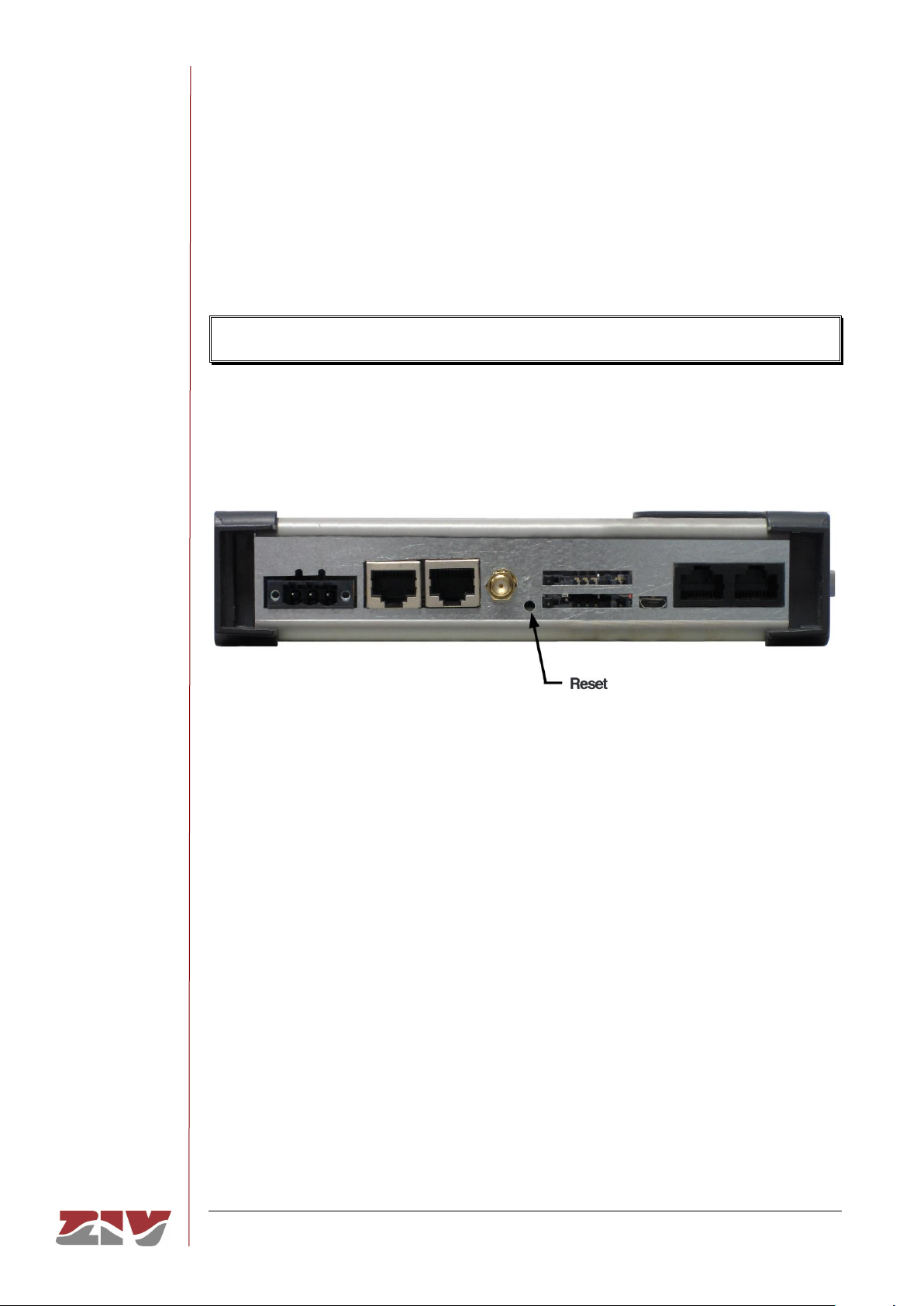
FIGURE 16 shows the detail of the push-button that loads the factory configuration in the
equipment, that is, deletes any configuration that the user had set and/or stored.
The touch is considered as whished when the push-button is pressed for at least 3
seconds.
Any type of tool with 3 mm diameter must be used.
FIGURE 16 Initialization push-button
Page 33

SIP-2
COMMUNICATION NODE TYPE SIP-2 33/145
USER GUIDE - Rev. 3 (January 2018)
3 LED SIGNALLING
The SIP-2 has on the front plate two basic LEDs (COM 0 and ON), and several specific
LEDs associated with the different interfaces.
The location and identification of the LEDs can be seen in FIGURE 17.
FIGURE 17 LEDs of the SIP-2
Page 34

SIP-2
COMMUNICATION NODE TYPE SIP-2 34/145
USER GUIDE - Rev. 3 (January 2018)
Basic LEDs
ON LED
Green. It is permanently lit when the equipment is
powered with an external power-supply voltage.
COM 0 LED
(service port)
Three-coloured. It flashes in green when there is emission
activity or, in red, when there is reception activity by the
COM 0 serial service interface.
It flashes in amber when there is simultaneously emission
and reception activity.
LED associated with the Fast Ethernet (10/100Base-Tx) ports
Link/Act 0 LED
Two-coloured. It stays on when the Eth 0 link is
established correctly, and flashes in the case of emission
or reception activity in the interface. It lights up in green
at 100 Mbit/s and in amber at 10 Mbit/s.
Link/Act 1 LED
Two-coloured. It stays on when the Eth 1 link is
established correctly, and flashes in the case of emission
or reception activity in the interface. It lights up in green
at 100 Mbit/s and in amber at 10 Mbit/s.
LEDs associated with the RS-232/RS-485 port (COM 1)
RS232/RS485 LED
Two-coloured. It stays on, in green, when the COM 1 port
is configured with a 2-wire RS-485 interface and, in red,
when is configured with a 4-wire RS-485 interface.
COM 1 LED
Three-coloured. It flashes, in green, in the case of data
transmission in the COM 1 port or, in red, in the case of
data reception in the COM 1 port.
It flashes in amber when there is simultaneously data
transmission and reception in the COM 1 port.
Page 35

SIP-2
COMMUNICATION NODE TYPE SIP-2 35/145
USER GUIDE - Rev. 3 (January 2018)
LED associated with the additional RS-232 port (COM 2)
COM 2 LED
Three-coloured. It flashes, in green, in the case of data
transmission in the COM 2 port or, in red, in the case of
data reception in the COM 2 port.
It flashes in amber when there is simultaneously data
transmission and reception in the COM 2 port.
LEDs associated with the WAN interface
Net LED
Green. It stays on when the wireless interface has been
registered in the operator network.
Session LED
Amber. It stays on when the operator session has been
established for the wireless interface.
Cvrg LED
Three-coloured. It stays on, indicating the coverage level.
Green: signal coverage is good.
Amber: signal coverage is average.
Red: insufficient coverage.
SIM A /B LED
Two-coloured. It stays on, indicating which of the two SIMs is in
use.
Green: SIM A (bottom position) is in use.
Red: SIM B (top position) is in use.
Page 36

SIP-2
COMMUNICATION NODE TYPE SIP-2 36/145
USER GUIDE - Rev. 3 (January 2018)
4 ACCESS TO THE EQUIPMENT
The SIP-2 can be managed locally and remotely, through a console or through a built-in
web server (http/https).
If management is carried out through the http server, it is assumed that the user has a
basic knowledge of IP addressing and networking devices such as hubs, switches, routers,
etc.
All the parameters controlling the equipment operation are described in detail in chapter 5,
using the HTML pages as an auxiliary graph example.
4.1 CONSOLE
The equipment provides a user console application called CLI (Command Line Interface),
accessible through the COM 0 connector (service port), a RJ-45 female connector in DCE
mode that operates at 115200 bit/s, with 8-bit characters, without parity and with a stop bit.
Access can also be obtained to the console remotely through a Telnet session.
Appendix B contains all the information required to use the CLI user console. The appendix
explains the access methods, local and remote, commands available on the console and
gives a step-by-step example of how to obtain information on the status and configuration
of the equipment.
4.2 HTTP SERVER
The HTTP server included provides access to the HTML pages giving access to all the
configuration data.
To execute the HTTPS protocol is necessary the installation of certificates. The procedure
for loading the certificates is described in section B.4 of Appendix B, Data structure in CLI.
Page 37

SIP-2
COMMUNICATION NODE TYPE SIP-2 37/145
USER GUIDE - Rev. 3 (January 2018)
The factory IP address of the equipment is 192.168.0.1, meaning it is possible to access
the HTTP server to configure it from the very start.
If the IP address of the SIP-2 equipment (server) is modified, the IP address of the client
equipment (computer) must be consequently modified.
If the SIP-2 equipment and the computer are connected directly or through a LAN (they
belong to the same network), the IP address of each of them must have the same network
number and a different host number, so the subnet mask must be the same for both. The
default gateway does not need to be configured.
If the SIP-2 equipment and the management computer belong to different LANs and the
connection between them is via WAN, their IP addresses may have a different network
number, but both must be connected to some device (default gateway) capable of
interconnecting LANs.
Next chapter describes the parameters of the HTML pages, and in FIGURE 18 is shown
the tree menu.
For information about the Reboot and Reflash commands see sections 5.18 and 5.19,
respectively.
The Apply, Save and Reboot commands request confirmation of the operation from the
user before it is actually executed.
Page 38

SIP-2
COMMUNICATION NODE TYPE SIP-2 38/145
USER GUIDE - Rev. 3 (January 2018)
5 CONFIGURATION AND MANAGEMENT
Configuration and management of the SIP-2 is performed through the console and through
access to the equipment HTML pages.
All the parameters controlling the equipment operation are described below in detail, using
the real HTML pages as an auxiliary graph example.
HTML page tree menu is shown in FIGURE 18.
Whenever changes are made, regardless of whether they are made through the console
or the HTTP server, the equipment must be informed what is to be done with them.
There are two options:
- the first is to execute the Apply command, which entails the immediate use of the
changes made.
- the second is to execute the Save command, which means that the changes will be
operative once the equipment is rebooted.
If accessing through the HTTP server, after making the changes and before executing
Apply or Save, the Send button must be pushed to allow the equipment to obtain the
new desired values.
If executing the Apply command, if the changes are required to be permanent, the Save
command must also be executed.
The only exceptions are changes affecting the SNMP configuration. Changes made to
the SNMP agent configuration will only be active after RESETTING the equipment. The
Apply command is not sufficient, and so the changes must previously be saved using
the Save command before requesting the re-initialisation.
Page 39

SIP-2
COMMUNICATION NODE TYPE SIP-2 39/145
USER GUIDE - Rev. 3 (January 2018)
FIGURE 18 HTML page tree menu
Standard version
104-101 Gateway version
Page 40
SIP-2
COMMUNICATION NODE TYPE SIP-2 40/145
USER GUIDE - Rev. 3 (January 2018)
5.1 GENERAL PARAMETERS
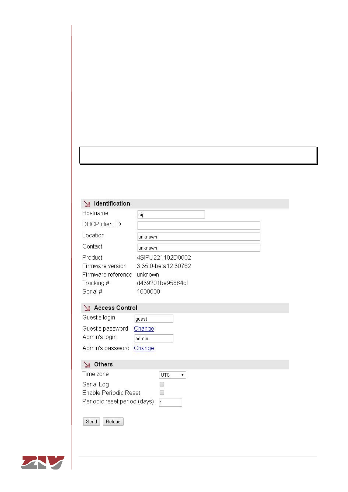
The general parameters are grouped on the first page, see FIGURE 19, which is shown
when the SIP-2 validates the user identity.
In addition to the configuration parameters, which will be described in the following
sections, as shown in the figure, the system provides information about the equipment
software, that is to say, version being executed, and equipment hardware, that is to say,
serial and tracking number.
The tree menu is permanently located on all the pages used by the HTTP server.
FIGURE 19 Main HTML page
Page 41

SIP-2
COMMUNICATION NODE TYPE SIP-2 41/145
USER GUIDE - Rev. 3 (January 2018)
5.1.1 Equipment identification
The identification zone has three parameters; the equipment name (hostname), its location
(location) and the contact data of the responsible person or company (contact). At least
one string of text is required, with at least one character.
The hostname is used automatically as a prompt value on the console.
The DHCP client ID configures the Client ID option of the RFC 2131 in DHCP configuration
requests. If this parameter is not configured, the MAC address of the interface on which the
request is sent is used as a default value for the Client ID.
The identification parameters coincide with those assigned with the same name in the
SNMP data.
5.1.2 Access control
Access control allows the user logins and associated passwords to be determined for the
two pre-established profiles: guest and admin.
The guest profile can only access query operations. On the contrary, the admin. profile has
access to all the system configuration data.
As summarised in TABLE 1, the default values of these parameters are guest and admin
as the logins, with passwd01 and passwd02 being the respective passwords.
It should be borne in mind that the system makes a distinction between upper and lower
case characters.
TABLE 1 System default access codes
Login
Password
Guest profile
guest
passwd01
Admin. profile
admin
passwd02
Page 42

SIP-2
COMMUNICATION NODE TYPE SIP-2 42/145
USER GUIDE - Rev. 3 (January 2018)
It is highly recommended to change at least the password of the admin. profile when
executing the first configuration in each equipment.
It is advisable to store the new password in some type of register as, should the new
password be forgotten, it is not possible to access the web server.
5.1.3 Others
This section deals with four parameters. The first of them establishes the hour zone in
relation to UTC.
The second parameter, Serial log, indicates whether the log data transmission on the
service serial port is activated from the initial start-up time (Checkbox control selected) or
not.
The third parameter, Enable periodic reset, allows users to indicate whether they want to
reboot the equipment automatically every so often. This is established in days through the
last parameter, Periodic reset period.
5.2 ADMINISTRATION
The equipment has an integrated http server for management purposes. The server
supports the http and the HTTPS protocols, and users can selectively enable their use and
the respective port.
FIGURE 20 Administration menu
The procedure for the installation of the certificates is described in section B.4 of
Appendix B, Data structure in CLI.
Page 43

SIP-2
COMMUNICATION NODE TYPE SIP-2 43/145
USER GUIDE - Rev. 3 (January 2018)
5.3 LAN CONFIGURATION
The LAN menu contains the configuration data for the network connection.
The main screen associated with the LAN menu is used to indicate whether the two
Ethernet interfaces form a two-port Ethernet switch (Dual Ethernet box not selected), or
if they are independent interfaces (Dual Ethernet box selected).
FIGURE 21 LAN configuration page
Port configuration is then carried out through the eth0 and eth1 submenus.
Configuration data associated with eth1 interface affect the behaviour of the equipment
only when the Dual Ethernet option is selected.
The screen related to each eth submenu of the LAN menu has two well differentiated
sections, which are described below.
FIGURE 22 eth configuration page
Page 44

SIP-2
COMMUNICATION NODE TYPE SIP-2 44/145
USER GUIDE - Rev. 3 (January 2018)
LAN:
The main IP address and its mask may be obtained automatically through the DHCP client,
which is called dynamic or NON-static configuration. The user may activate this feature
through the CheckBox type control with the Static IP label. When the control is ticked, the
equipment uses the data provided by the user.
IP Alias:
The equipment is capable of responding to IP addresses different from the main one if they
have been previously added through the Add CommandButton.
5.4 SERIAL PORT CONFIGURATION
The Serial menu provides access to the equipment serial port configuration screen. This
port is configurable by software for RS-232 interface or RS-485 (2-wire or 4-wire) interface.
FIGURE 23 Serial port (COM) configuration page
The screen related to the Serial menu has two well differentiated sections, which are
described below. See section 1.2 for more general information about the port
interconnection.
Physical:
• #. It establishes the equipment physical port number. Port 1 for port COM1.
• Interface. It establishes the type of the interface: RS-232 or RS-485 with 2-wire or
4-wire.
Page 45

SIP-2
COMMUNICATION NODE TYPE SIP-2 45/145
USER GUIDE - Rev. 3 (January 2018)
• Baudrate. It establishes the serial port speed. The available values are the
following: 600, 1200, 2400, 4800, 9600, 19200, 38400, 57600 and 115200 bit/s.
• Databits. It establishes the character length. The available values are the
following: 5, 6, 7 and 8.
• Parity. It establishes the parity. The available values are the following: odd, even or
none.
• Stopbits. It establishes the number of stop bits. The available values are the
following: 1 and 2.
• Flow control. It establishes the flow control mechanism. The available values are
the following: none, hardware (control signals) and software (Xon and Xoff).
Logical:
• #. It establishes the equipment physical port number. Port 1 for port COM1.
• Mode. It establishes the port operation mode: flow or emulator. Flow, that is,
serial port mode. The emulator mode implies the activation of the HAYES modem
emulator additional characteristic, and it should only be selected to define a
ModemEmulator behaviour for the port, which is similar to a HAYES modem. In this
last case, there are additional options in the ModemEmulator menu.
• Protocol. It establishes the protocol of the data to be encapsulated; the possible
values are the following: raw (without processing, it is transparent to the
information), packed, (the data will be grouped in packets according to the related
parameters, being also transparent as regards the encapsulated information), one
of the identifiers of the telecontrol protocols being hold (iec101_1, iec101,
iec102_1, iec102, pid1, dlms, gestel, sap20, twc, dnp3, procome, iec103,
modbusrtu, modbusrtu_cc) or the policy-based mode (policybased).
• Policy. This field should be configured when the policybased mode has been
established in the Protocol parameter. It establishes an identifier, whose policy
should be configured in the Policy submenu of the Flow menu.
• Packed time (ms). This field should be configured when the packed mode has
been established in the Protocol parameter. It establishes the maximum waiting
time after receiving the last character, in ms, before sending a packet with the data
received so far. It forces sending the data for inactivity time when not reaching the
data established as desired packet size (see following parameter).
• Packed size. This field should be configured when the packed mode has been
established in the Protocol parameter. It establishes the maximum number of
characters to be transmitted in a packet on the network.
Page 46

SIP-2
COMMUNICATION NODE TYPE SIP-2 46/145
USER GUIDE - Rev. 3 (January 2018)
5.5 WAN CONFIGURATION
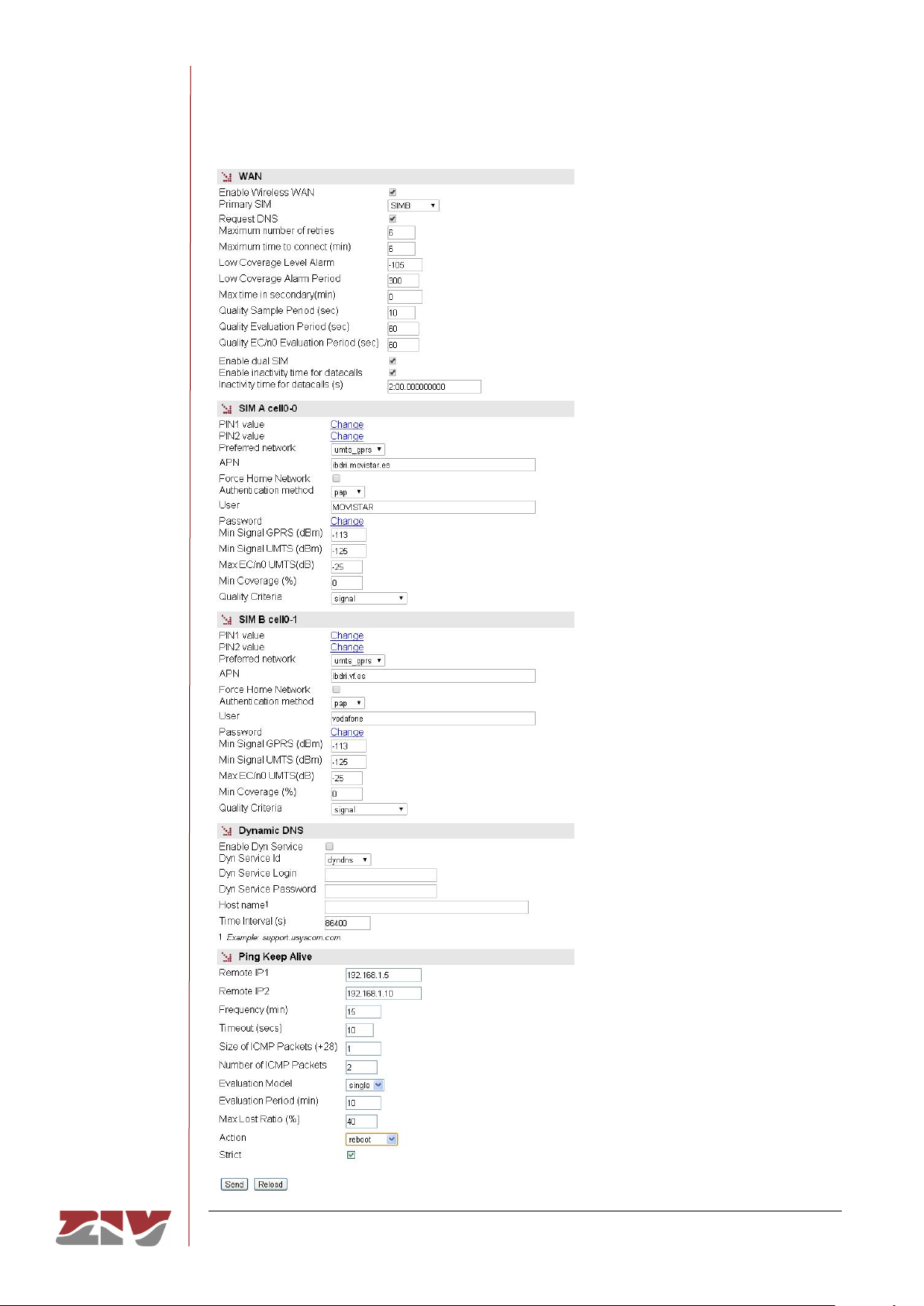
This menu only appears when the SIP-2 equipment has the optional wireless WAN
interface.
5.5.1 cell0 submenu
This submenu is used to configure the wireless interface data. The submenu has four
different sections, which are described below.
WAN:
• Enable Wireless WAN. This allows the WAN interface of the equipment to be
enabled and disabled by selecting ON and OFF, respectively.
Selecting the ON option will make the equipment try a new
GPRS/UMTS/HSDPA/LTE session, in accordance with the subscriber data (PIN,
APN, Authentication method, user, password). In the case of dual SIM
functionality, the subscriber data will be those corresponding to the primary SIM.
The OFF option disables the WAN interface, and is the default option.
Consequently, you should enable this option if you want the GPRS/UMTS/LTE
service, after FIRST configuring the necessary parameters for establishing the
operator session.
• Primary SIM. In the case of dual SIM functionality, this permits users to determine
which of the two available SIMs will act as the primary one: SIMA or SIMB. In this
operating mode the SIM that is not selected is therefore the secondary or back-up
SIM. It is also possible to establish an operating mode with alternation of the SIMs
(alternated) each time the equipment is started up, as well as an operating mode
for random selection of the primary SIM each time the equipment is started up
(random).
• Request DNS. Tick this box and the equipment will request the addresses for DNS
servers if connected to the GPRS/UMTS/LTE service.
• Maximum number of retries. This gives the number of retries (3 to 10) that can be
made to try and establish the operator session. If the number of retries is used up,
the equipment will be rebooted.
In the case of dual SIM functionality, the number of retries is for each of the SIMs.
In this way, once the number of retries with the primary SIM has been used up, the
equipment will try to establish connection using the secondary SIM. If it is not
possible to connect with the secondary SIM, once the number of retries has been
used up, or if the secondary SIM is disabled, the equipment will be rebooted.
Page 47
SIP-2
COMMUNICATION NODE TYPE SIP-2 47/145
USER GUIDE - Rev. 3 (January 2018)
FIGURE 24 WAN interface configuration page
Page 48

SIP-2
COMMUNICATION NODE TYPE SIP-2 48/145
USER GUIDE - Rev. 3 (January 2018)
• Maximum time to connect (minutes). This specifies the time in minutes (3 to 20)
for the equipment to wait in order to obtain the WAN IP address from the operator.
If after that time, a WAN IP has not been obtained, the equipment will be rebooted.
In the case of dual SIM functionality, it must be taken into account that the
Maximum time to connect counter starts operation at the same time that the
Maximum number of retries counter. In this way, the equipment will be rebooted
when one of the two counters reaches at zero, that is to say, when it is not possible
to connect once the number of retries of both SIMs has been used up (see
Maximum number of retries counter) or once the time configured in the Maximum
time to connect counter has been used up.
• Low Coverage Level Alarm. It specifies the coverage level under which the low
coverage level alarm should be activated.
• Low Coverage Alarm Period. It specifies the time the coverage level should
remain below the level indicated in the previous paragraph before the low coverage
alarm is activated.
• Max time in secondary (minutes). This parameter is associated with the dual
SIM functionality. It allows the time during which the equipment is connected to the
secondary SIM to be limited. After that time, the equipment will again try to connect
to the primary SIM. The maximum time permitted is 1440 minutes.
• Quality Sample Period (sec). This parameter defines the period of time that the
equipment uses for sampling the received signal measure, RSSI when operating
on a 2G network or RSCP and EC/n0 when the network is 3G.
• Quality Evaluation Period (sec). The user defines the period of time and thus,
indirectly, the number of samples of the received signal measure to determine
compliance with minimum quality. The signal value is individualized for each
possible operator and network type, see Min Signal GPRS and Min Signal UMTS.
The criteria for determining if the level is correct or not is that all samples of the
current evaluation period not meet the minimum set.
• Quality EC/n0 Evaluation Period (sec). This parameter is equivalent to the
above, but the measure that is evaluated is EC/n0, which only applies in 3G
networks. The threshold value is set for each operator with Max EC/n0 UMTS
parameter. The criteria for determining if the level is correct or not is that all
samples of the current evaluation period exceed the maximum set.
Page 49

SIP-2
COMMUNICATION NODE TYPE SIP-2 49/145
USER GUIDE - Rev. 3 (January 2018)
• Enable dual SIM. This box must be ticket to determine whether the equipment will
use the secondary SIM or not. It enables the options: SIMB, alternated and
random.
• Enable inactivity time for datacalls. Selecting this box determines if the
equipment will use the following parameter.
• Inactivity time for datacalls (s). It establishes the inactivity time in seconds that
will imply the voluntary and controlled shutdown of the GSM datacall connection.
SIM A cell-0 y SIM B cell0-1:
• PIN 1 and PIN 2 values. These are the safety codes associated with the SIM card.
Normally, PIN1 is sufficient to access the general services provided by the
operator. Check that the code entered is correct. Entering a wrong code will block
the SIM card.
Once the PIN 1 and PIN 2 values are introduced from the Change option,
execute the send command of said option, and then, if you want the values to be
applied and saved in the equipment, DO NOT forget to execute the apply and
save commands from the main menu tree.
• Preferred network. Only for the UMTS interface. This allows the equipment
behaviour to be specified in the case of a failure in UMTS/HSDPA coverage. When
UMTS is selected, the equipment will always try to connect to a UMTS/HSDPA
network. This option therefore involves the disconnection of the equipment, due to
the lack of UMTS/HSDPA reception. If UMTS/GPRS is selected, the equipment will
try to connect to a UMTS/HSDPA network, but if there is no UMTS/HSDPA
coverage it will connect to a GPRS network. With this option, the equipment will
permanently monitor the UMTS/HSDPA network coverage, and as soon as the
UMTS network becomes available again, it will switch from a GPRS network to a
UMTS/HSDPA network.
• APN. This establishes the identity of the operator access point.
• Force Home Network. On ticking this box connection with the operator of the local
network associated with the SIM card is forced (home network). If this option is
selected, the equipment will not connect to any operator other than the one
specified.
Page 50

SIP-2
COMMUNICATION NODE TYPE SIP-2 50/145
USER GUIDE - Rev. 3 (January 2018)
• Authentication method. The authentication method to be used when establishing
the PPP session must be selected. The possible values are None, PAP and CHAP.
• User Name. User name established by the operator during the authentication
process (see preceding point).
• Password. Password established by the operator to validate the user name in the
preceding point. The password is not shown for security reasons and so when it is
changed (Change option), it must be entered twice.
Once the Password is introduced from the Change option, execute the send
command of said option, and then, if you want the password to be applied and
saved in the equipment, DO NOT forget to execute the apply and save
commands from the main menu tree.
• Min Signal GPRS (dBm). This parameter allows a minimum coverage level to be
specified (in dBm) as a quality parameter for the GPRS (2G) connection. When the
coverage level is below this value the equipment will not try to establish the
operator session and will remain disconnected. The default values are -113 dBm
(0%, no coverage) and -51 dBm (100%, coverage).
TABLE 2 relates the AT command for coverage measurement (AT+CSQ), the
value in dBm of said coverage, and the level of coverage the equipment is
receiving, which is shown in the coverage bar on the upper strip of any of the
pages on the user interface.
• Min Signal UMTS (dBm). This parameter allows a minimum coverage level to be
specified (in dBm) as a quality parameter for the UMTS (3G) connection. When the
coverage level is below this value the equipment will not try to establish the
operator session and will remain disconnected. The default values are -113 dBm
(0%, no coverage) and -51 dBm (100%, coverage).
TABLE 2 relates the AT command for coverage measurement (AT+CSQ), the
value in dBm of said coverage, and the level of coverage the equipment is
receiving, which is shown in the coverage bar on the upper strip of any of the
pages on the user interface.
Page 51

SIP-2
COMMUNICATION NODE TYPE SIP-2 51/145
USER GUIDE - Rev. 3 (January 2018)
• Max EC/n0 UMTS (dB). This parameter specifies the maximum threshold of the
EC/n0 measure to be considered as acceptable.
• Min Coverage (%). The system calculates the coverage as a percentage from the
received power RSSI to 2G networks, or a combination of the received power
(RSCP) and the measured EC/n0, in the case of 3G networks. This parameter sets
the minimum threshold required to be evaluated.
• Quality criteria. The equipment samples several quality data depending on the
network technology in use. This parameter configures what action or combination
shall be evaluated in each of the periods. The options are:
o Signal: The system will analyze well RSSI (2G) or RSCP (3G) as the only
measure of quality.
o Coverage: The system shall refer the measure Min. Coverage with the
corresponding configured value to evaluate the compliance of the required
level.
o Signal_and_ecn0: The system will monitor both RSCP and EC/n0 and, for
the quality criteria to be satisfied, both measures must meet the
corresponding thresholds simultaneously and for the entire evaluation
period.
o Signal_or_ecn0: The system will monitor both RSCP and EC/n0 and
quality criteria are satisfied if one of the two measures meets the
corresponding threshold for the entire evaluation period.
o ecn0: The system will analyze EC/n0 as the only measure of quality.
Applicable only operating on 3G networks.
If the network in use is 2G, the Signal_and_ecn0, Signal_or_ecn0 and ecn0
criteria are interpreted as Signal. This establishes the criteria for 3G networks, and
allows the equipment to be operative although the actual network be 2G,
temporarily or permanently.
Page 52

SIP-2
COMMUNICATION NODE TYPE SIP-2 52/145
USER GUIDE - Rev. 3 (January 2018)
TABLE 2 AT command for coverage measurement (AT+CSQ)
AT+CSQ
Coverage (GPRS)
Coverage (3G)
Received power
Number of bars on
screen
0
0%
0%
<-113 dBm
- 1 0%
0%
-111 dBm
- 2 1%
1%
-109 dBm
-
3
1%
3%
-107 dBm
-
4
2%
4%
-105 dBm
- 5 2%
6%
-103 dBm
- 6 3%
7%
-101 dBm
-
7
3%
8%
-99 dBm
-
8
4%
11%
-97 dBm
- 9 5%
14%
-95 dBm
-
10
6%
15%
-93 dBm
1
11
11%
21%
-91 dBm
2
12
17%
29%
-89 dBm
2
13
23%
35%
-87 dBm
3
14
29%
43%
-85 dBm
3
15
35%
49%
-83 dBm
4
16
41%
57%
-81 dBm
5
17
47%
66%
-79 dBm
5
18
53%
74%
-77 dBm
6
19
59%
85%
-75 dBm
6
20
65%
99%
-73 dBm
7
21
71%
100%
-71 dBm
8
22
77%
100%
-69 dBm
8
23
83%
100%
-67 dBm
9
24
90%
100%
-65 dBm
10
25
92%
100%
-63 dBm
10
26
94%
100%
-61 dBm
10
27
96%
100%
-59 dBm
10
28
97%
100%
-57 dBm
10
29
98%
100%
-55 dBm
10
30
99%
100%
-53 dBm
10
31
100%
100%
>-51 dBm
10
>31
0%
Unknown
-
Page 53

SIP-2
COMMUNICATION NODE TYPE SIP-2 53/145
USER GUIDE - Rev. 3 (January 2018)
Dynamic DNS:
A dynamic DNS service permits the assigning of a DNS name to equipment with a
non-permanent IP address, and the Dynamic DNS client is responsible for updating it
when it changes. In this way, from the user standpoint the equipment is always
accessible via a DNS name, and so it is not necessary to always know the IP address
assigned.
The Dynamic DNS client is entrusted with connecting to the chosen server and
updating the IP address.
To use the Dynamic DNS client, users must first register the DNS name of the
equipment with the service provider. The client can only update the IP address.
The parameters are as follows:
• Enable Dyn Service. Enables the Dynamic DNS client execution.
• Dyn Service Id. Allows you to select one of the dynamic DNS service providers
supported.
• Login y Password. Establishes the user name (login) and password (password)
for accessing the service provider.
• Host name. Name of the equipment registered with the service provider, i.e., the
name of the equipment used to identify the SIP-2 via DNS.
• Time interval (seconds). Time between accesses for the Dynamic DNS client to
update the IP address.
Ping Keep Alive:
This is a facility for checking the status of the WAN interface.
• Remote IP1 and Remote IP2. This establishes the IP addresses of the equipment
with which accessibility will be checked, through the sending of ICMP (ping)
packets. If the fields are at 0.0.0.0 this means the "Ping Test" function is disabled. It
is sufficient for any one of the remote equipment to respond to consider the
accessibility test valid. A field with the value 0.0.0.0 means that the option is not
enabled.
Page 54

SIP-2
COMMUNICATION NODE TYPE SIP-2 54/145
USER GUIDE - Rev. 3 (January 2018)
• Frequency (minutes). This allows the time passing between the sending of ICMP
(ping) packets to be specified.
• Timeout (secs). This allows the maximum response time to the ICMP (ping)
packets sent by the Ping Keep Alive function to be specified. It admits a range
between 5 and 60.
• Size of ICMP packets. This allows the size of the ICMP packet to be specified.
The configuration consists of indicating the extra bytes to be added to the smallest
ICMP packet, which is, by default, 28 bytes.
• Number of ICMP packets. This allows the number of ICMP packets that are sent
in each verification to be specified.
• Evaluation Model. This establishes the model for the evaluation of the
accessibility test. The options are: single and period. The single model
establishes that, if some execution of the test fails, the behaviour of the equipment
is the one defined in the Action parameter. The period model establishes, by
means of the two following parameters, a test evaluation period and an admitted
failure percentage within it.
• Evaluation Period (min). When the Evaluation model parameter is configured as
period, this establishes a period between 1 and 6000 within which a failure of the
accessibility test can be produced. All the responses to the Ping Keep Alive
packets sent in this period make the universe of samples that will be considered to
decide about the execution of Action according to the fulfilment of the criteria
established by means of the following parameter.
• Max Lost Ratio (%). This allows the maximum admitted percentage of failure in
the Evaluation period to be specified for the results of the Ping Keep Alive
messages.
• Action. This establishes the desired behaviour of the equipment if the accessibility
test is failed. The options are: None (no action taken), Reconnect (set up a new
GPRS/UMTS/LTE session) or Reboot (reboot the equipment).
Page 55
SIP-2
COMMUNICATION NODE TYPE SIP-2 55/145
USER GUIDE - Rev. 3 (January 2018)
• Strict. This option allows users to inhibit the accessibility test in the presence of
traffic. If the option is not activated, the test will only be executed when the period
of time indicated in frequency without traffic has passed. When the option is
enabled, the test will be performed regardless of whether traffic is present or not.
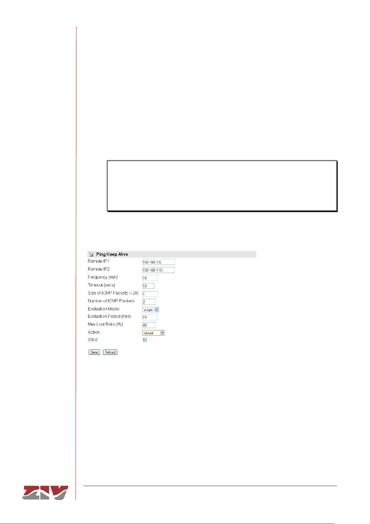
In the figure given as an example in the Ping Keep Alive configuration, connectivity
of the IP addresses 192.168.1.5 and 192.168.1.10 is verified every 15 minutes by
sending 2 ICMP packets of 29 bytes (28+1). In case of failure, the behaviour is
Single and, in this case, if there is no response to the "Ping Test", the equipment
will be rebooted.
To prevent "Ping Test" failures occurring due to the simultaneous reception of
traffic, the equipment will check the activity through the WAN interface for 30
seconds prior to executing the "Ping Test". If the reception of traffic is detected,
the "Ping Test" function will not be executed.
FIGURE 25 Example of the Ping Keep Alive configuration
5.5.2 Tunnel submenu
A tunnel can be defined as a virtual connection which emulates an end-to-end connection
between two nodes connected through a complex network, which may be public like
Internet or private.
To configure a tunnel, it is necessary to define the start and end points of the tunnel and the
traffic to be sent through it.
Page 56

SIP-2
COMMUNICATION NODE TYPE SIP-2 56/145
USER GUIDE - Rev. 3 (January 2018)
There are two types of unsafe (unencrypted) tunnels: IPIP and GRE. The difference
between them is that IPIP tunnels can only encapsulate IPv4unicast traffic, whereas GRE
tunnels admit multicast traffic.
To guarantee privacy and safety, the data circulating on the tunnel can be encrypted
through the IPSec cipher protocol. It can be configured through the VPN menu.
FIGURE 26 Tunnel submenu of the WAN menu
The configuration parameters are:
• Tunnel ID. This establishes the name of the virtual tunnel-like device.
• Type. This establishes the desired tunnel type; GRE or IPIP.
• Tunnel IP. This establishes the IP address associated with the virtual tunnel
device, whose identity is the value of the Tunnel ID parameter. The address must
be the host address, but it admits the inclusion of the associated net mask and also
its configuration in an indirect form, through the equipment device identifier, in
which case the IP address configured in this interface is assigned with a host mask.
• Tunnel Source. This establishes the local interface through which the tunnel traffic
will be routed. In the case of WAN interfaces, it may be cell0-0 (identifies SIM A) or
cell0-1 (identifies SIM B). Otherwise, it will be a virtual network identifier from one
of the VLANs in the equipment.
• Remote GW. This establishes the IP address of the equipment at the other end of
the tunnel, that is to say, the terminator.
• Remote network. The remote subnetwork connected to the point at the end of the
tunnel (Remote GW) whose traffic passes through the tunnel. If any is selected, all
traffic not accessible locally or based on specific rules will be sent through the
tunnel.
Page 57
SIP-2
COMMUNICATION NODE TYPE SIP-2 57/145
USER GUIDE - Rev. 3 (January 2018)
• Enable. This permits a tunnel to be enabled or disabled, by ticking or not ticking
the respective Enable box.
• Tunnel description. A descriptive field permitting the indication of data about the
tunnel, for example, its usefulness.
• Preshared key. A key that is exchanged between the equipment at both ends of
the tunnel, for the purpose of establishing it. It must be configured in both
terminators (Tunnel IP and Remote GW). For it to be effective, the associated
Enable box must be ticked.
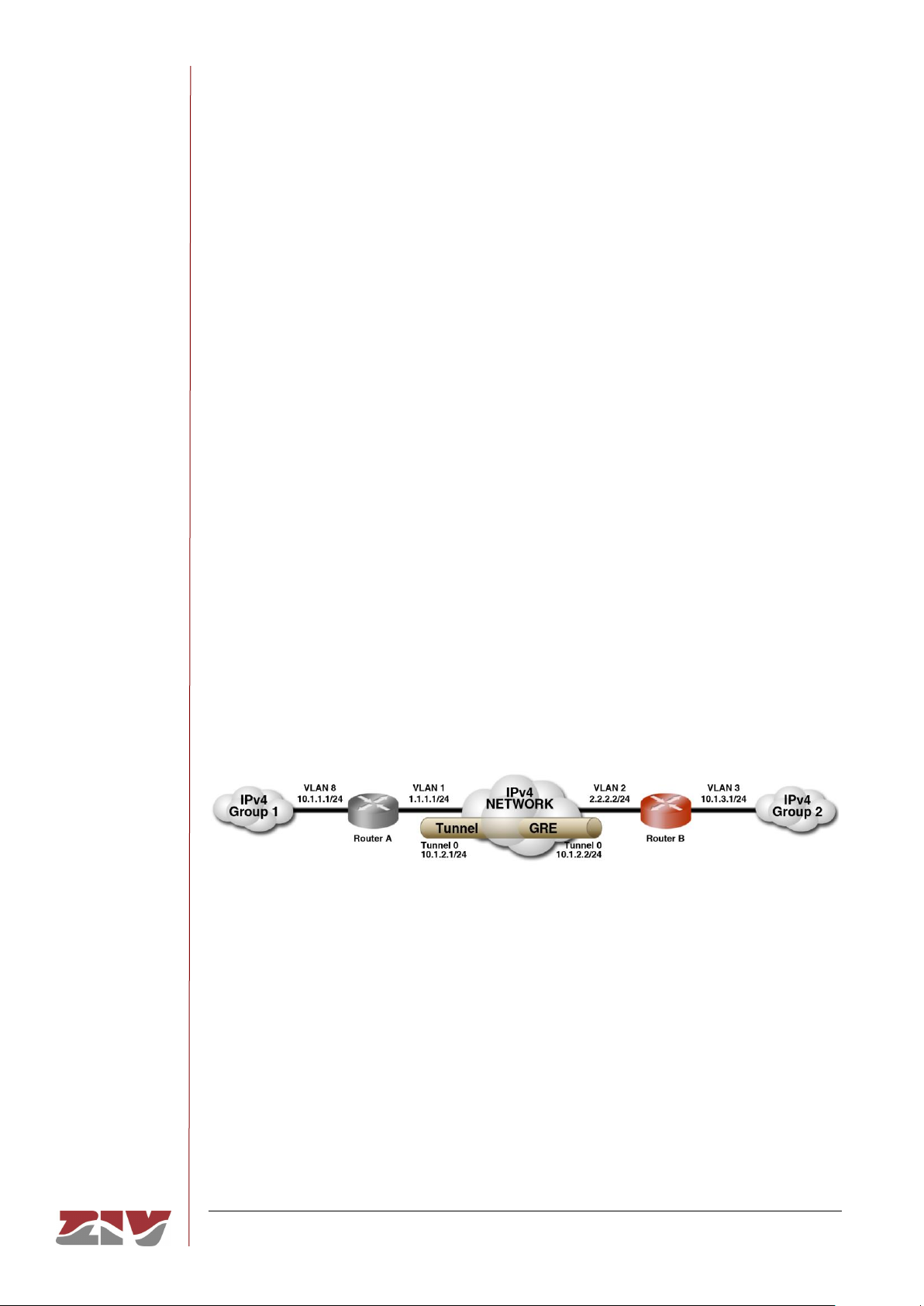
Example:
An example is given below which allows the different parameters referred to above to be
identified, with specific values. The GRE tunnel is established between Routers A and B,
connected through an IPv4 network; the connection could well be the Internet.
Routers A and B route the traffic between the equipment belonging to Group 1 and Group 2
as if both routers were directly connected to each other, since they both have an IP address
in the same segment, 10.1.2.1 and 10.1.2.2 respectively, which are the IP addresses
assigned locally to each end of the tunnel; they do this in a transparent manner on the IPv4
network
FIGURE 27 Tunnel submenu of the WAN menu
In router A, the configuration would be:
• Tunnel ID. Tunnel0.
• Type. GRE
• Tunnel IP. 10.1.2.1/24 (IP address of the virtual Tunnel0 device).
• Tunnel Source. vlan1 (Local interface in which the local address 1.1.1.1/24 is
configured).
Page 58

SIP-2
COMMUNICATION NODE TYPE SIP-2 58/145
USER GUIDE - Rev. 3 (January 2018)
• Remote GW. 2.2.2.2/24 (tunnel terminator address).
• Remote network. 10.1.3.0/24 (IP network located at the remote end of the tunnel).
In router B, the configuration would be:
• Tunnel ID. Tunnel0.
• Type. GRE
• Tunnel IP. 10.1.2.2/24 (IP address of the virtual Tunnel0 device).
• Tunnel Source. vlan2 (Local interface in which the local address 2.2.2.2/24 is
configured).
• Remote GW. 1.1.1.1/24 (tunnel terminator address).
• Remote network. 10.1.1.0/24 (IP network located at the remote end of the tunnel).
5.6 STATIC ROUTES CONFIGURATION
The Statics Routes option of the Routing menu provides access to the configuration
screen through which the user can provide the system with the static and permanent data
for the routing service.
The screen has two well differentiated sections. Explicit static routes are configured in the
Static Routes section. The address acting as a route by default in the case that the service
has no specific data for reaching a destination is configured in the Default Static Routes
section.
If the equipment has the optional wireless interface, the operator will not only provide the
IP address of the interface but also establish a default router associated with that
interface, which takes precedence over any configuration established by the user.
Page 59
SIP-2
COMMUNICATION NODE TYPE SIP-2 59/145
USER GUIDE - Rev. 3 (January 2018)
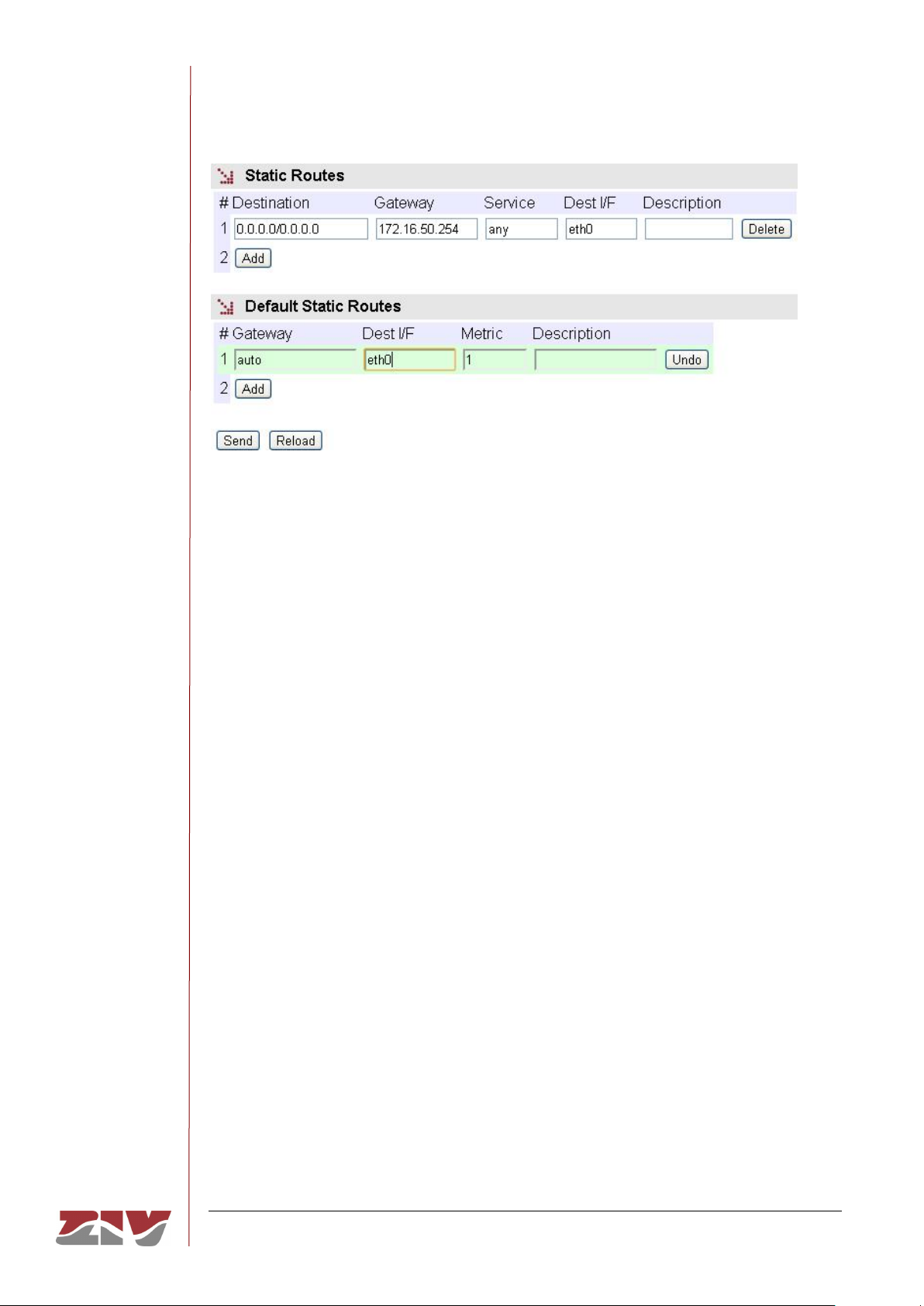
FIGURE 28 Static routes configuration page
The parameters for configuring a static route are:
• Destination. This allows the IP address to be specified, and the remote or destination
network subnet mask. The field requires the values to be entered in the IP address
format. Example: 192.168.0.0/255.255.255.0 or 192.168.0.0/24.
• Gateway. This allows the IP address of the router to which the traffic destined for the
remote network of the previous field must be sent.
• Service. This allows an additional filter to be established in the remote IP address for
determining the selection of the next jump. The condition is established based on a
specific service (tcp/udp/icmp). After the service the port number (1÷65535) must be
indicated, separated by two points. The default value is any, that is to say, the route
applies for all types of traffic (only the IP destination is taken into account). Example:
tcp:5000, which means that all the packets with tcp traffic on port 5000 will be sent to
the indicated router.
• Dest I/F (Destination interface). This allows the interface through which the routed
traffic coinciding with this route will be sent.
• Description. This permits a description of up to 15 alphanumerical characters to be
specified.
Page 60
SIP-2
COMMUNICATION NODE TYPE SIP-2 60/145
USER GUIDE - Rev. 3 (January 2018)
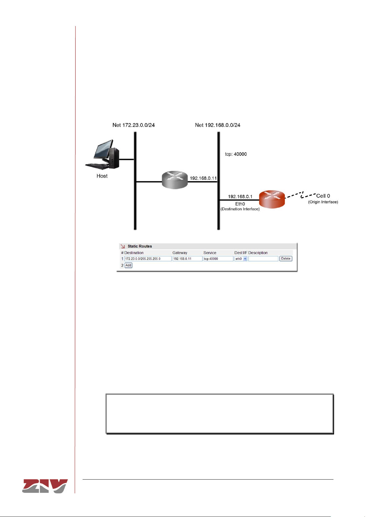
Example:
The figure shows an example of assigning a static route between two different network
segments. All the TCP packets of port 40000 can reach the network segment 172.23.0.0/24
through router 192.168.0.11.
FIGURE 29 Example of how a static route is configured
The default parameters for configuring a static route are:
• Gateway. This allows the IP address of the next router to be specified for routing
traffic whose destination does not coincide with any known route.
• Dest I/F (Destination interface). This permits the specification of the interface
through which traffic routed to the router indicated in the previous field will be sent.
• Metric. This permits a value to be established originating from among the default
different routes that could be created. A higher metric means a lower priority.
If the wireless interface is operative, this parameter must be different and higher
than 1, the value 10 being recommendable as values higher and next to 1 could
be reserved to other routes established by the operator.
• Description. This permits a description of up to 15 alphanumerical characters to
be specified.
Page 61

SIP-2
COMMUNICATION NODE TYPE SIP-2 61/145
USER GUIDE - Rev. 3 (January 2018)
5.7 DNS SERVER CONFIGURATION
The DNS servers option of the Routing menu provides access to the configuration screen
through which the user can configure the DNS server addresses manually.
The configuration parameters are:
• Enable DNS resolver. Enables the DNS service. The DNS servers can be
configured manually when the option is selected.
• IP Address. Specifies the IP addresses of DNS servers. For the addresses to be
effective, the Enable DNS resolver box must be selected.
For proper operation of this service, the DHCP client must NOT be configured.
FIGURE 30 DNS server configuration page
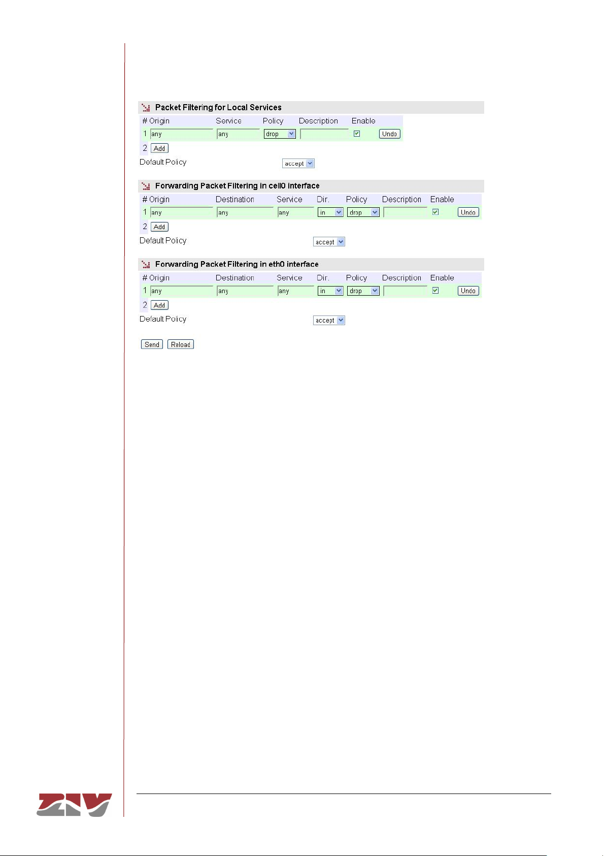
5.8 FILTERING CONFIGURATION
The Filtering menu permits firewall functionalities, defining which traffic is allowed and
which traffic is rejected and the application of additional conditions to the traffic processed
through the routing function.
The menu parameters are divided into three quite different blocks, which are:
Filtering of packets for local services (http, Telnet or any).
Filtering of packets through the incoming/outgoing service for the GPRS/UMTS/LTE
(cell0) interface, if the equipment has the WAN interface.
Filtering of packets through the incoming/outgoing service for the Ethernet (eth) interface.
Page 62
SIP-2
COMMUNICATION NODE TYPE SIP-2 62/145
USER GUIDE - Rev. 3 (January 2018)
FIGURE 31 Filtering menu configuration page
The configuration parameters in each block are:
• Origin. This allows the IP source of the traffic to be specified, i.e., from a specific
IP address or any IP address (any). The default value is any. The specification of a
particular IP address requires the values to be entered in the IP address format.
Example: Subnet (192.168.50.0/255.255.255.0 or 192.168.50.0/24) or Host
(192.168.50.5/255.255.255.255 or 192.168.50.5/32 ó 192.168.50.5). Only present
in the sections in which this makes sense.
• Destination. This allows the IP source of the traffic to be specified, i.e., to a
specific IP address or from any IP address (any). The default value is any. The
specification of a particular IP address requires the values to be entered in the IP
address format.
Example: Subnet (192.168.50.0/255.255.255.0 or 192.168.50.0/24) or Host
(192.168.50.5/255.255.255.255 or 192.168.50.5/32 or 192.168.50.5).
• Service. This allows any type of traffic to be specified (any) or a specific traffic
(tcp/udp/icmp). The default value is any. If a specific traffic is indicated, the port
number can be indicated together with the service, if required (1÷65535) or a
range. Example: tcp or tcp:23 or udp:5001-5005.
• Dir. This allows the traffic direction to be specified, i.e., whether it is incoming (in)
or outgoing (out).
Page 63
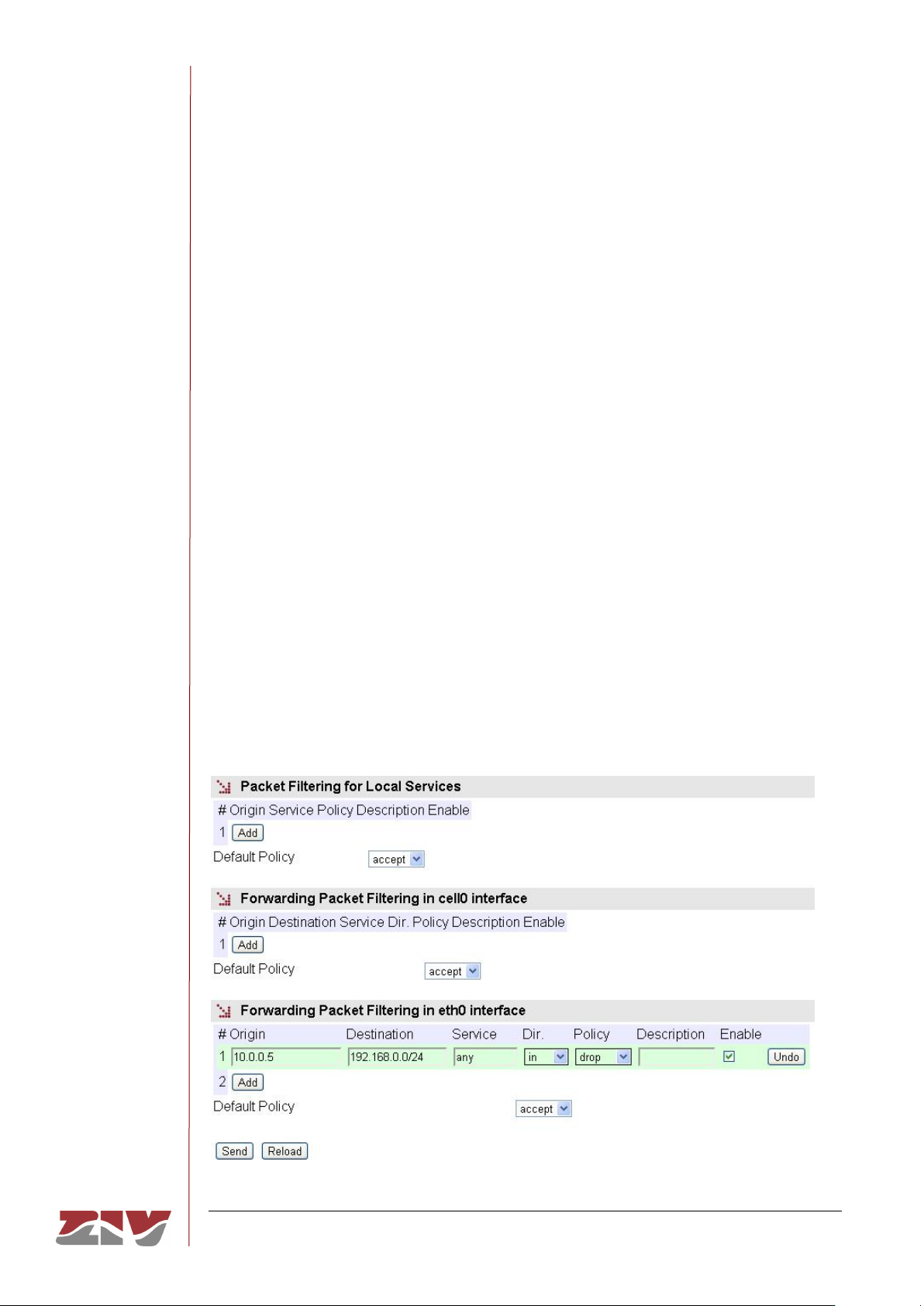
SIP-2
COMMUNICATION NODE TYPE SIP-2 63/145
USER GUIDE - Rev. 3 (January 2018)
• Policy. This allows the filtering policy to be specified (accept, drop or reject).
When the filtering policy is accept, only packets complying with the established rule
are accepted. When the filtering policy is drop, on the other hand, packets
complying with the established rule are dropped. The reject filtering policy also
rules out packets complying with the established rule, but unlike drop, when the
packet is ruled out, the appropriate ICMP message is sent to the source address of
the packet.
• Description. This permits a description of up to 15 alphanumerical characters to
be specified.
• Default Policy. This allows the behaviour of the equipment filtering to be
determined as regards not being included in any specific rule of the respective
section.
Example:
A filtering policy is to be established to eliminate traffic present in the ethernet (eth0)
interface coming from host 10.0.0.5, whose destination is within the IP range
192.168.0.0/24. The eth0 block configuration will be that shown in the figure.
FIGURE 32 Example of filtering configuration page
Page 64
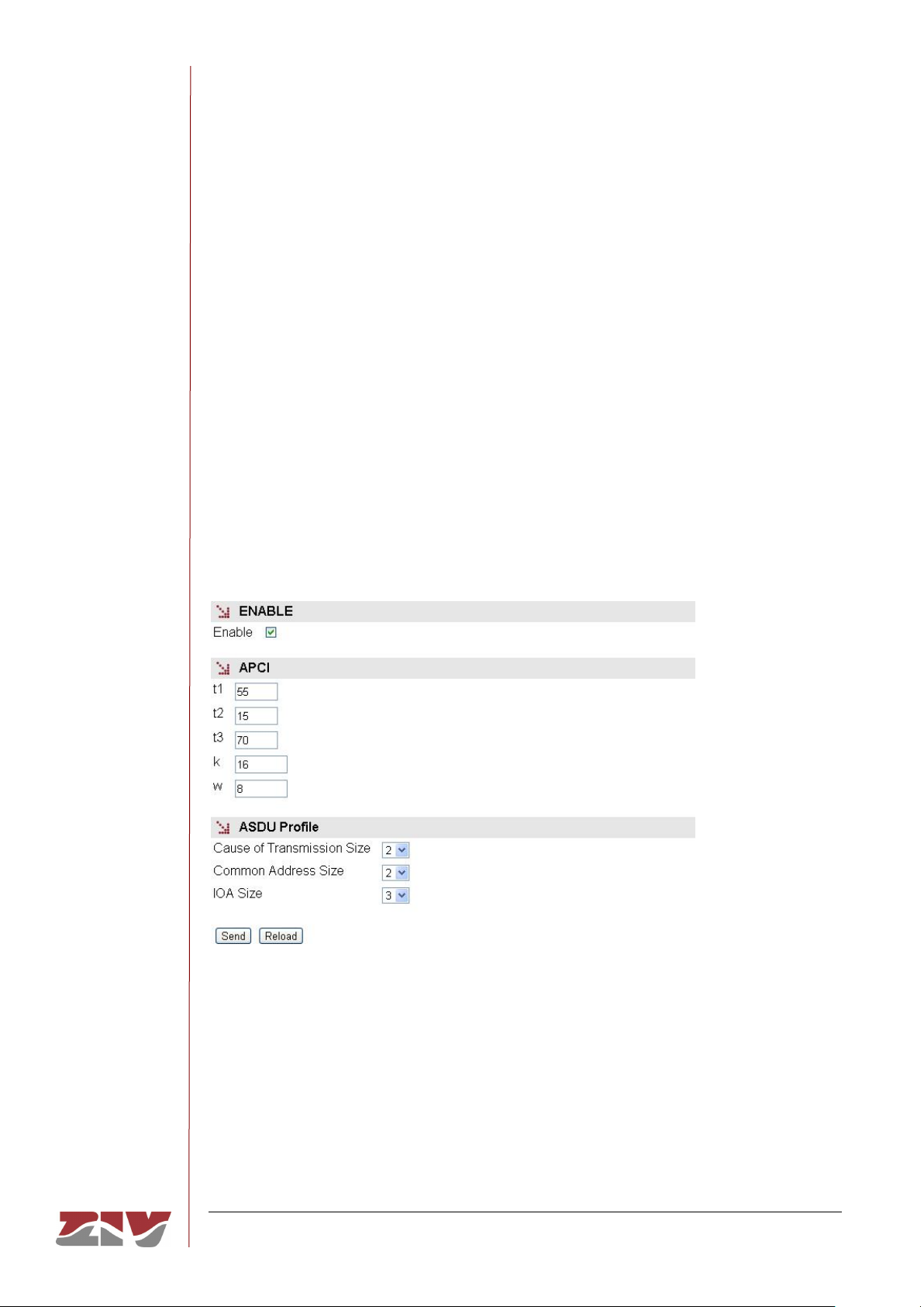
SIP-2
COMMUNICATION NODE TYPE SIP-2 64/145
USER GUIDE - Rev. 3 (January 2018)
5.9 GW 104-101 CONFIGURATION
This menu only appears when the SIP-2 has the Gateway 104-101 functionality.
The GW 104-101 menu contains the parameters that must be programmed to allow the
transparently management of RTUs that do not use the variant IEC 60870-5-104 from a
control center that operates with IEC 60870-5-104.
The GW 104-101 menu contains three submenus: IEC 60870-5-104, IEC 60870-5-101 and
RTU, which are described below.
5.9.1 IEC 60870-5-104 configuration
This submenu allows the operating parameters of the APCI layer according to the
IEC 60870-5-104 standard to be configured, and the parameters used in the format of the
ASDUs.
FIGURE 33 IEC 60870-5-104 submenu of GW 104-101 menu
The configuration parameters are divided into three blocks, which are described below:
ENABLE:
• Enable. This permit the GW 104-101 function to be enabled.
Page 65

SIP-2
COMMUNICATION NODE TYPE SIP-2 65/145
USER GUIDE - Rev. 3 (January 2018)
APCI:
In the IEC 60870-5-104 standard the use of the APCI protocol to transport information
packets at application level (ASDU) over standard transport layers is detailed. The
APCI protocol acts as a client of the TCP transport layer. The standard also indicates
the parameters that the user has available to establish its behaviour, apart from
establish procedures to be followed by the APCI protocol.
This submenu allows the user to configure all the parameters detailed by the
IEC 60870-5-104 standard, except for the t0 parameter that does not apply to the
telecontrol remotes but applies to the control center.
The parameters, their meaning and range of possible values are described below.
• Parameter t1. The t1 parameter sets the maximum waiting time for receiving
confirmation of a message at APCI level. When the established time is elapsed, the
connection will be finished. The possible values are from 1 to 255 seconds with a
resolution of 1 second.
• Parameter t2. The t2 parameter sets the maximum time that an APCI entity can
wait from receiving an APCI message and sending the confirmation message,
either through an information message on the contrary direction or by a control
message for this purpose.
The standard establishes that it is imperative that the value of the parameter t2 be
lower than the parameter t1. The possible values and resolution are identical to
those of t1 parameter.
• Parameter t3. The t3 parameter sets the period of inactivity on an established
APCI connection, which involves the transmission of TEST messages to ensure the
persistence of the connection. The possible values and resolution are identical to
those of t1 and t2 parameters.
• Parameter k. The k parameter sets the maximum number of pending confirmation
messages that can manage the APCI entity for each established connection. It
admits a range from 1 to 32767.
• Parameter w. The w parameter sets the maximum number of messages received
by an APCI entity that involves the corresponding confirmation message
transmission, either through a user message on the contrary direction or, in the
absence of traffic in transmission, by a control message. It admits a range equal to
that of k parameter.
The standard recommends that the value of w be less or equal to two thirds of the
value of k, in order to avoid a blocking situation in the absence of traffic in one of
the two ways. The system indicates the user this situation when configuring data
but does not require compliance with the recommendation.
Page 66

SIP-2
COMMUNICATION NODE TYPE SIP-2 66/145
USER GUIDE - Rev. 3 (January 2018)
ASDU profile:
• Cause of Transmission Size (COT). It determines the number of bytes to be used
in the filed Cause of Transmission of the ASDU. The admitted values are 1 or 2,
indicating the number of octets that will constitute the field.
When the Cause of Transmission is configured with 2 octets, the second octet
contains the Address (identifier of center 104), which allows the existence of
multiple connections 104 (of different centers 104) on the same link 101.
• Common Address Size. It establishes the length, in number of octets, of the
address field that identifies the remote, admitting as values 1 or 2. This field
determines the number of remotes to be manageable by a control center.
• IOA size. It establishes the length of the field IOA (Information Object Address) in
number of octets. The possible values are 1, 2 or 3.
5.9.2 IEC 60870-5-101 configuration
This submenu allows the typology of the telecontrol remote connection to the SIP-2
equipment to be configured, and the mechanism used for display and error recovery on the
IEC 60870-5-2 link.
FIGURE 34 IEC 60870-5-101 submenu of GW 104-101 menu
The configuration parameters are described below:
• Mode. It determines the type of connection between the telecontrol remote and the
COM port of the SIP, the only option available being the Point-to-Point connection.
• Transmission mode. The parameter admits two possible values: dcd and idle
mode. In the first case, the mechanism for recovering an error condition is via state
changes of the dcd signal. In the second case, the mechanism is by timed
inactivity.
Page 67

SIP-2
COMMUNICATION NODE TYPE SIP-2 67/145
USER GUIDE - Rev. 3 (January 2018)
• Idle (bits)/DCD (msec) Period. The meaning of this field depends on the chosen
transmission mode. dcd mode is the minimum idle time to resynchronize signal. It is
measured in units of time of 10 ms, and it is limited to a maximum value of 5.
idle mode is the free-line time (unused) that is necessary for resynchronize after
detecting an error. It is measured in bit intervals, the value 0 not being allowed. To
deactivate the idle condition the value named “IDLE time” (with a value by default
equal to 10) must be configured with a value equal to 0.
The new value equal to 0 will indicate to the GW104-101 that it must not consider the
standard idle times for eliminating messages.
5.9.3 RTU configuration
This submenu allows the identity parameters of the telecontrol remote (CA) to be
configured, and the operating parameters of the IEC 60870-5-2 link.
FIGURE 35 RTU submenu of GW 104-101 menu
The configuration parameters are described below:
BALANCED RTUs:
• #. It establishes the equipment physical port number. Port 1 for port COM1.
• Common Address Size. It establishes the length of the address field that is to be
used by the remote in number of octets. The possible values are 1, 2 or 3.
• Common Address. It determines the telecontrol remote address.
• Cause of Transmission Size. It establishes the length of the CoT field that is to be
used by the remote in number of octets. The possible values are 1 or 2.
• IOA Size. It establishes the length of the field containing the address of the objects
in the remote in number of octects. The possible values are 1, 2 or 3.
Page 68

SIP-2
COMMUNICATION NODE TYPE SIP-2 68/145
USER GUIDE - Rev. 3 (January 2018)
• Link Address Size. It determines the size of the link address associated with the
telecontrol remote. It may not be identical with the length of the Common Address
field.
• Link Address. It determines the link address associated with the telecontrol
remote. It may differ from the Commom Address.
• Link Direction. It establishes the behaviour of SIP-2 with respect to IEC 60870-5-2
link. The encoding of the two possible directions is:
o A to B. From station type A to station type B.
o B to A. From station type B to station type A.
The COM interface of SIP-2 must be configured depending on the behaviour of the
telecontrol remote, that is, if the remote acts as station type B_to_A, the SIP-2 must
be configured as type A_to_B, and vice versa.
• ASDU Queue. It activates the queue of GW 104-101 that stores the received
ASDU from the telecontrol remote, and already confirmed to the remote, and that
have not yet been transmitted to the control center or, if they have been
transmitted, the confirmation from the control center has not yet been received.
• ASDU Queue Time (hours). It establishes the persistence time of messages in the
queue of the GW 104-101 from the moment there is no connection with a control
center. When the configured time is elapsed, the stored messages are deleted. It is
useful when the queue is active.
• Synchro. It indicates if the GW 104-101 function must synchronize to the
telecontrol remote automatically, that is, without intervention of the control center.
• Synchro Period (Minutes). It sets in minutes the transmission period of the
synchronism messages generated by the GW 104-101 function.
• Link Test. The GW 104-101 function can execute the line test included in the
IEC 60870-5-2 link procedures in order to determine if the connection with the
remote is still operative. This feature is requested by activating this parameter.
• Link Test Period (min). This parameter sets the frequency with which the test line
(see previous parameter) will take place.
Page 69

SIP-2
COMMUNICATION NODE TYPE SIP-2 69/145
USER GUIDE - Rev. 3 (January 2018)
UNBALANCED RTUs:
• #. It establishes the equipment physical port number. Port 1 for port COM1.
• Common Address Size. It establishes the length of the address field that is to be
used by the remote in number of octets. The possible values are 1, 2 or 3
• Common Address. It determines the telecontrol remote address.
• Cause of Transmission Size. It establishes the length of the CoT field that is to be
used by the remote in number of octets. The possible values are 1 or 2.
• IOA Size. It establishes the length of the field containing the address of the objects
in the remote in number of octects. The possible values are 1, 2 or 3.
• Link Address Size. It determines the size of the link address associated with the
telecontrol remote.
• Link Address. It determines the link address associated with the telecontrol
remote.
• ASDU Queue. It activates the queue of GW 104-101 that stores the received
ASDU from the telecontrol remote, and already confirmed to the remote, and that
have not yet been transmitted to the control center or, if they have been
transmitted, the confirmation from the control center has not yet been received.
• ASDU Queue Time (hours). It establishes the persistence time of messages in the
queue of the GW 104-101 from the moment there is no connection with a control
center. When the configured time is elapsed, the stored messages are deleted. It is
useful when the queue is active.
• Synchro. It indicates if the GW 104-101 function must synchronize to the
telecontrol remote automatically, that is, without intervention of the control center.
• Synchro Period (Minutes). It sets in minutes the transmission period of the
synchronism messages generated by the GW 104-101 function.
• Polling Time(s). The unbalanced RTUs should be consulted periodically by the
GW 104-101 about the availability on data because the 104 Control Center will not
do so. This parameter establishes the frequency of queries.
• Tx InterFrame Time (ms). It establishes a minimum time between the
transmission of messages to the remote.
Page 70

SIP-2
COMMUNICATION NODE TYPE SIP-2 70/145
USER GUIDE - Rev. 3 (January 2018)
5.10 NAT CONFIGURATION
This feature is used when the SIP-2 operates as a router.
NAT is the IP address translation service which allows users to combine the use of private
IP address without this preventing them from accessing resources with a public IP address,
or preserve the address schema in different interconnected network areas.
The NAT menu defines the rules that allow IP addresses to be selectively translated and
change the transmission service ports.
It is important to bear in mind that the NAT service has a default rule.
The correct operation of services based on its operation in analysing data which can
be changed by the NAT rules could be altered by the presence of this default rule,
since the services have a specific order of execution.
If not using NAT, you should eliminate this default rule.
FIGURE 36 NAT configuration page
The configuration parameters are:
• Origin. This establishes a range of IP addresses. It admits the value any, in the
case that the origin IP address is not relevant.
• Destination. This establishes a range of IP addresses. It admits the value any, in
the case that the IP destination address is not relevant.
• Service. This establishes conditions related to service, understood as the protocol
(tcp/udp/icmp) and port (1 to 65535 or a range). It admits the value any, in the
case that the service is not relevant. Example: tcp or tcp:23 or udp:5001-5005.
• Transl. Origin. This establishes the IP address that must replace the origin IP. An
IP address may be specified or the respective interface identifier. In the case of not
wanting to change the original address, the value must be original.
Page 71

SIP-2
COMMUNICATION NODE TYPE SIP-2 71/145
USER GUIDE - Rev. 3 (January 2018)
• Transl. Dest. This establishes the IP address that must replace the destination IP.
An IP address may be specified or the respective interface identifier. In the case of
not wanting to change the original address, the value must be original.
• T. Orig. Port. This establishes the identifier of the port that must replace the origin
port in the packet. It admits a range configuration. In the case of not wanting to
change the original port, the value must be original.
• T. Dest. Port. This establishes the identifier of the port that must replace the
destination port in the packet. It admits a range configuration. In the case of not
wanting to change the destination port, the value must be original.
• Description. This permits a description of up to 15 alphanumerical characters.
5.11 DHCP SERVER CONFIGURATION
The SIP-2 has a built-in DHCP server which allows IP addresses to be assigned
automatically to the equipment requesting this.
The configuration parameters are:
• Enable DHCP server. This allows the DHCP service to be activated. The DHCP
server is operative when the option is selected.
• First IP Addr. Allows the first IP address of the IP addresses pool managed by the
DHCP Server to be specified.
• Last IP Addr. Allows the last IP address of the IP addresses pool managed by the
DHCP Server to be specified.
• Maximum number of leases. Allows the maximum number of IP addresses
simultaneously assigned in use to be specified.
• Mask. This establishes the net mask that will communicate with the DHCP clients.
• Default Gateway. This establishes the default router address (Default Gateway)
that will communicate with the DHCP clients.
• Lease time. This allows the time in seconds to be specified for an IP address to be
assigned following a request from a DHCP client. After the indicated time, if the
DHCP has not requested a renewal, the IP address will be considered available for
dealing with new requests.
Page 72

SIP-2
COMMUNICATION NODE TYPE SIP-2 72/145
USER GUIDE - Rev. 3 (January 2018)
• 1st DNS server. This allows the specification of the primary DNS server IP
address which the DHCP server will provide to the DHCP client. If left blank
(0.0.0.0) no information on DNS servers will be sent to the client.
• 2nd DNS server. This allows the IP address of a secondary DNS server to be
specified to the DHCP client. If left blank (0.0.0.0) this means that no information
will be sent to the client in this respect.
• WINS server. This allows the IP address of the WINS server to be established,
which will be notified to the DHCP client. WINS is a names resolution system
owned by Microsoft for equipment executing the Windows operating system.
• DNS Domain Name. This establishes the DNS domain to be used by the client for
creating its full DNS name.
• Boot TFTP Server. This establishes the IP address of the TFTP server that stores
the remote boot file, thereby allowing the client to execute a request to download
the file.
• Bootfile Name. This establishes the name of the remote boot file which the client
will request from the TFTP server configured in the preceding point.
FIGURE 37 DHCP server configuration page
Page 73

SIP-2
COMMUNICATION NODE TYPE SIP-2 73/145
USER GUIDE - Rev. 3 (January 2018)
5.12 VPN CONFIGURATION
This menu only appears when the SIP-2 equipment has the optional wireless WAN
interface.
As already mentioned in the Tunnel submenu of the WAN menu (section 5.5.2), the
tunnels are a method for establishing the opportune end-to-end links between equipment.
Unlike the GRE and IPIP tunnels, IPSec tunnels are characterised by being safe; this
means the information is transmitted so that its content cannot be accessed by others,
which is particularly important if the IP network upon which it is established is not controlled
by the user, or is not public.
To create an IPSec tunnel a security association must be established in each terminator:
Tunnel IP (origin) and Remote GW (destination).
An IPSec connection between two ends requires three steps:
Establishing an IKE Security association (IKE Policy).
Establishing an IPSec Security association (IPSec Association).
Sending protected data through the IPSec connection.
The parameters used in each of these steps are configured as independent blocks, thereby
permitting their use in more than one tunnel at the same time and reducing the need to
duplicate configuring information.
The DPD (Dead Peer Detection) function is a mechanism for supervising operativity in the
IPSec tunnels established.
Page 74
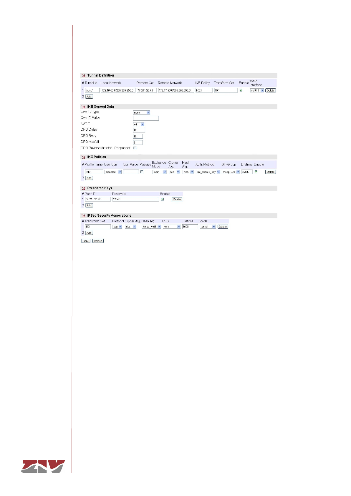
SIP-2
COMMUNICATION NODE TYPE SIP-2 74/145
USER GUIDE - Rev. 3 (January 2018)
FIGURE 38 VPN menu
The sections and their configuration parameters are as follows:
Tunnel Definition:
• Tunnel ID. The identifier of the virtual tunnel device to be established.
• Local Network. This establishes the range of origin IP addresses that will be
transmitted in the tunnel. It provides a filter at the original IP address level. The any
value is accepted, as well as IP network addresses, through the IP/Mask format.
• Remote GW. IP address of the terminator remote equipment in the IPSec tunnel.
• Remote Network. The range of IP addresses that can be reached at the remote
end of the tunnel. It is equivalent to a static route in the sense that all data
coinciding with the specified range will be sent through the tunnel. The special
value any is also accepted.
• IKE Policy. This selects the set of previously-defined parameters that will be used
for establishing the IKE Security association.
Page 75

SIP-2
COMMUNICATION NODE TYPE SIP-2 75/145
USER GUIDE - Rev. 3 (January 2018)
• Transform Set. This selects the set of previously-defined parameters that will be
used for establishing the IPSec Security association.
• Enable. This enables the configured tunnel. It allows the user to have configured
operative or non-operative tunnels, as wished.
• Valid Interface. This indicates the valid device identifier upon which the tunnel can
be established. It operates like an additional filter. The value any is accepted.
IKE General Data:
• Own ID Type. This indicates the type of identification to be used by the equipment.
The options are none, address entailing the use of the IP address, fqdn, which
involves using a domain (e.g. foo.domain.com), or user_fqdn, entailing the use of
an e-mail address (e.g. [email protected]).
• Own ID Value. The own identity value in the case of selecting an option other than
none in the preceding parameter.
• NAT-T. It enables the use of the option NAT-T, allowing the IPSec protocol to
function correctly when NAT services are crossed. The options are off, when the
user does not want it to be enabled or it will not be accepted if proposed by the
remote end, which is also the default value. On means that the option will be used
when detecting the presence of NAT services between both ends, and force
entails its use regardless of whether or not the presence of NAT services is
detected.
• DPD Delay. This parameter sets the time between Hello messages transmitted for
the tunnel supervision function. The valid range of values is 0 to 1200, and the
units are seconds. 0 means the supervision is not executed.
• DPD Retry. This establishes the waiting time for a response to a Hello message
transmitted, in seconds. If no response is received from the remote end within this
time, the equipment considers that a supervision failure has occurred.
• DPD Maxfail. The value of this parameter is the maximum admitted number of
failures to respond to a Hello message. If this maximum number is reached it is
considered that the tunnel is not available and an attempt will be made to restore it.
• DPD Reverse Initiator-Responder. This option allows the use of the DPD
supervision service with tunnels ended by Cisco equipment that execute a nonstandard variation.
Page 76

SIP-2
COMMUNICATION NODE TYPE SIP-2 76/145
USER GUIDE - Rev. 3 (January 2018)
IKE Policies:
• Profile name. This identifies the set of parameters being configured to establish an
IKE Security association, so that it can be used by one or more configured tunnels.
• Use fqdn (Full Qualified Domain Name). This indicates the type of identification
to be used by the equipment. The options are disabled, entailing the use of the IP
address, fqdn, which involves using a domain (e.g. foo.domain.com), or
user_fqdn, entailing the use of an e-mail address (e.g. [email protected]).
• fqdn value. This parameter determines the domain or e-mail address to be used
after selecting one of the two options indicated in the preceding section.
• Passive. When this option is executed, the equipment will not take the initiative in
establishing the tunnel and wait to receive the request from the remote end.
• Exchange Mode. This establishes the mode for exchanging codes. The mode
must be the same at both ends for the exchange to be successful. The options are
main, aggressive and base.
• Cipher alg. Cipher alg. This determines the cipher algorithm to be used for
exchanging codes. The available algorithms are DES, 3DES and AES.
• Hash Alg. This determines the hash algorithm used for authentication during the
code exchange. The available options are MD5 (Message Digest 5) and SHA1
(Secure Hash Algorithm).
• Auth. Method. This establishes the code-generating mechanism. Only the
exchange of previously-established codes is available as a method.
• DH Group. Selection of the Diffie-Hellman (DH) Modular Exponential (MODP)
group for creating codes. Group 1 (768 bits, option modp768), group 2 (1024 bits,
option modp1024) and group 5 (1536 bits, option modp1536) are available).
• Lifetime. The valid term for the security association in exchanging codes. When
the established time is up, a new association is renegotiated. The value establishes
the time in seconds.
• Enable. This indicates that the group of parameters specified can be used (active
option) or that it cannot be used (inactive option).
Page 77

SIP-2
COMMUNICATION NODE TYPE SIP-2 77/145
USER GUIDE - Rev. 3 (January 2018)
Preshared Keys:
• Peer IP. This establishes the IP address of the remote tunnel equipment (Remote
GW) for which the password of the next parameter is defined.
• Password. The password is stored in this parameter.
• Enable. This indicates whether the configured password can be used (active
option) or not (inactive option).
IPSec Security Associations:
• Transform set. This identifies the set of parameters being configured to establish
an IPSec Security association so that it can be used by one or more configured
tunnels.
• Protocol. The protocol establishes which of the two types of encapsulation will be
used. ESP (Encapsulating Security Payload) provides ciphering and authentication
for each packet, and AH (Authentication Header) only provides the authentication
service.
• Cipher alg. This determines the cipher algorithm to be used for encrypting the user
data. The available algorithms are DES, 3DES and AES.
• Hash alg. This determines the hash algorithm used for authentication. The
available options are MD5 (Message Digest 5) and SHA1 (Secure Hash Algorithm).
A third option exists, non-auth, which means the authentication is not included.
The authentication and ciphering options can be combined in different modes. If the AH
protocol is selected, only the hash algorithm choice will be taken into account, and on
the contrary if the ESP protocol is selected, the encryption is always present with the
cipher algorithm selected, and the authentication may be included with either MD5 or
SHA1, or it may not be included if the non-auth value is selected.
• PFS (Perfect Forward Secret). If the option is enabled, this means that each new
code renegotiated must be completely separated from the previous one. The
remote end must accept the PFS option for the establishment to be successful.
This option provides additional security but a greater processing load.
• Lifetime. The maximum validity time for a security association. When the
established time is up, a new association is renegotiated. The value establishes the
time in seconds.
Page 78
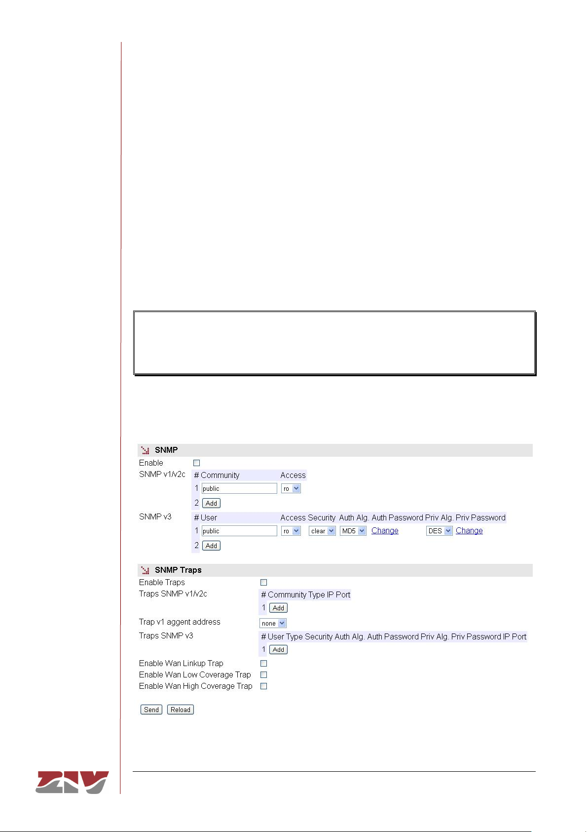
SIP-2
COMMUNICATION NODE TYPE SIP-2 78/145
USER GUIDE - Rev. 3 (January 2018)
• Mode. The IPSec provides two operating modes; the first is tunnel, which means
the original packet is completely encapsulated in an additional IP head, and the
second is transport, meaning that the original head is used without adding an
extra one.
5.13 SNMP CONFIGURATION
The equipment has an SNMP agent with the capacity to generate spontaneous messages
to control equipment, based on that protocol.
The agent admits the emitting of messages based on the SNMPv1 [1], SNMPv2c [2] and
SNMPv3 protocol, and the selection of the type of message, trap and inform.
Changes made to the SNMP agent configuration will only be active after RESETTING
the equipment. The Apply command is not sufficient, and so the changes must
previously be saved using the Save command before requesting the reboot.
FIGURE 39 SNMP menu
Page 79
SIP-2
COMMUNICATION NODE TYPE SIP-2 79/145
USER GUIDE - Rev. 3 (January 2018)
The configuration parameters are:
• Enable: Enables/disables the execution of the SNMP agent. The agent is operative
when the option is selected.
• Community: Parameter associated with SNMPv1/v2c. Tabulate information that
allows several operating profiles to be defined, including the rights of access
(Access) associated with each one, read only rights (ro) or reading/writing rights
(rw). The profiles are called communities.
• User: Parameter associated with SNMPv3. Tabulate information that allows the
users, including the privileges and the operating mode associated with each user,
to be defined. That is to say, the rights of access (Access), read only rights (ro) or
reading/writing rights (rw), and the way in which the data transference (Security)
will be carried out, without encryption (clear), authentication (auth) or authentication
and encryption (priv).
In case of authentication transmission (auth), it is necessary to select the type of
algorithm (Auth Alg.), MD5 or SHA, and establish the authentication password
(Auth Password). The password establishes the word to be used to generate the
authentication information. The authentication word must be known by the receiver
in order to be able to verify the authenticity of the identity of the transmitter.
In case of encrypted transmission (priv), in addition to select the type of
authentication algorithm (Auth Alg.) and authentication password (Auth Password),
it is necessary to select the cipher algorithm (Priv Alg.), DES o AES, and establish
the cipher password (Priv Password).
The password is not shown for security reasons and so when it is changed
(Change option), it must be entered twice.
Once the Password is introduced from the Change option, execute the send
command of said option, and then, if you want the password to be applied and
saved in the equipment, DO NOT forget to execute the apply and save
commands from the main menu tree.
Page 80

SIP-2
COMMUNICATION NODE TYPE SIP-2 80/145
USER GUIDE - Rev. 3 (January 2018)
SNMP Traps:
• Enable Traps: Enables/disables the generation and transmission of spontaneous
messages by the SNMP agent. The agent will send the traps selected by the user
when the different events occurred.
• Traps SNMPv1/v2c: Tabulate information allowing several destination equipment
for the traps to be defined.
For each of the spontaneous SNMP message addressees, a profile must be
provided, which must be included in the spontaneous message, the SNMP protocol
version with which it will be coded, the IP address of the addressee and the UDP
port to which the messages will be sent. The default value established in the
standard is port 162. It can be changed to adapt to the operating data of each
addressee.
The transmission of the messages in a confirmed (inform) way is only accepted for
the v2c and v3 versions of the protocol.
• Trap v1 agent address: This establishes the IP address the agent will
communicate as being its own when sending spontaneous messages. This
parameter is only used to create the traps when using SNMPv1.
• Traps SNMPv3: Tabulate information allowing several destination equipment for
the notifications to be defined.
The receivers are identified by means of their IP address and the UDP port to
which the notifications are to be sent. The standard UDP port for the SNMP
notifications is the 162, being the value by default.
The Type control is used to establish whether the transmission of the notifications
is carried out in an unconfirmed (trap) or confirmed (inform) way.
• Enable Digital Input Change Trap: Enables/disables the transmission of
spontaneous messages by the SNMP agent, indicating the status changes of the
digital inputs (see section 2.5).
Page 81

SIP-2
COMMUNICATION NODE TYPE SIP-2 81/145
USER GUIDE - Rev. 3 (January 2018)
5.14 NTP CONFIGURATION
The equipment has an NTP client, meaning that it can synchronise time-related information
by accessing NTP servers. The NTP [3] protocol is a standard that is widely used in
TCP/IP-based networks. It admits the use of several NTP servers simultaneously, and the
option of using authentication.
FIGURE 40 NTP menu configuration page
The usage parameters are:
• Enable: Enables/disables the execution of the NTP client. The client is operative
when the option is selected.
• Authentication keys: Tabled information allowing the definition of different
authentication codes to be used subsequently in communicating with the different
NTP servers.
• Server: Tabled data that includes the NTP servers access data. Each row contains
data related to one NTP server.
• Accept broadcast: This establishes whether the NTP client will accept messages
transmitted with broadcast-type NTP messages.
Page 82

SIP-2
COMMUNICATION NODE TYPE SIP-2 82/145
USER GUIDE - Rev. 3 (January 2018)
For each of the NTP servers configured, an IP address must be provided, as well as the
type of IP message it will use to access the individual server (unicast) or collective Server
(manycast), the minimum time between requests, with the parameter establishing the
exponent of the power of 2 in seconds; the maximum time between requests, also as the
exponent of the power of 2 in seconds, and a selection option that determines whether
authentication should be used, in which case it is necessary to indicate which previouslydefined code the client with the server in question will use.
5.15 ACCESS CONFIGURATION
The equipment offer users several means of access: operating console, access via http
server (web) and telnet.
Local users predefined in the system are always present but an external resources can be
used to validate users for different types of access, for which reason the user database is a
centralised and independent resource with respect to the equipment itself. For this purpose
the equipment has a TACACS+ client.
TACACS+ (Terminal Access Controller Access Control System) is a remote
authentication protocol used to manage access to servers and communication devices; it
provides separate authentication, authorisation and registration services.
The general configuration parameters are the following:
• Server IP 1. This establishes the IP address of the primary TACACS+ server.
• Server IP 2. This establishes the IP address of the secondary TACACS+ server.
• Encrypted. This permits user to select whether the equipment communication with
the TACACS+ servers must be made in the ciphered mode or not.
• Secret Shared Key. This establishes the code to be used for ciphering the
communication when the encrypted option is active.
• Guest Privilege Level. This establishes the privilege level (0 to 15) of the guest
profile (guest). This level must be the same that the one established in the
TACACS+ server.
• Admin Privilege Level. This establishes the privilege level (0 to 15) of the
administrator profile (admin). This level must be the same that the one established
in the TACACS+ server.
Page 83
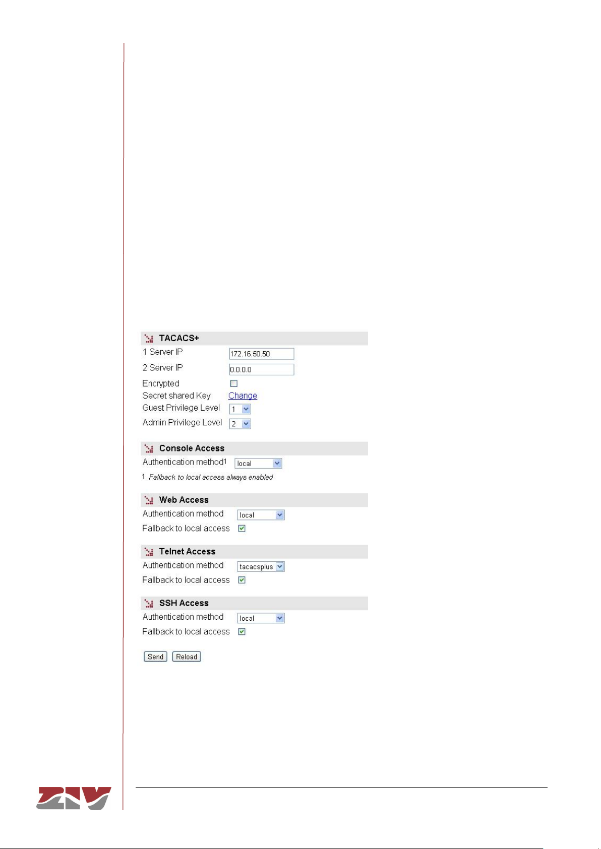
SIP-2
COMMUNICATION NODE TYPE SIP-2 83/145
USER GUIDE - Rev. 3 (January 2018)
The parameters associated with each access option (console, web access, telnet and
SSH) are the following:
• Authentication method. This establishes whether the user validation must be
made locally or by consulting the configured tacacsplus servers.
• Fallback to local access. When this option is enabled, if there is no accessibility
to the configured TACACS+ servers, users are permitted to validate themselves
with local user names. If the option is disabled, and the TACACS+ servers are not
accessible, users will not be granted access. Access through the console has this
option permanently enabled, for which reason it is not configurable.
FIGURE 41 Access menu configuration page
Page 84

SIP-2
COMMUNICATION NODE TYPE SIP-2 84/145
USER GUIDE - Rev. 3 (January 2018)
5.16 DATA FLOW CONFIGURATION
The Flow menu basically permits the virtual ports (TCP/UDP) configuration parameters to
be established, as well as to define the connections and/or flows between any of the
available interfaces. See section 1.2 for more general information about the port
interconnection.
The UDP protocol is a connectionless protocol. The data is transmitted as
independent blocks (packets).
The TCP protocol is a connection-oriented protocol; thus, a prior establishment phase
is necessary, and with it the data is transmitted as a continuous character flow.
5.16.1 Encapsulation protocols
Each one of the ports should be configured for operation with a specific protocol, either to
operate in transparent mode (raw and packed), with one of the telecontrol protocols
being hold or with a policy defined by the user.
Some protocols have multiple identifiers, which not only indicate the protocol itself, but also
the size of the link address, when the standard requires it as a user option.
The protocols without multiple identifiers are the following:
• pid1, dlms, gestel, sap20, twc, dnp3, procome and iec103.
The protocols with multiple identifiers and values related to them are listed below:
• iec101_1. IEC 60870-5 101, with FT1.2 frame and a link address size of 1 byte.
• iec101. IEC 60870-5 101, with FT1.2 frame and a link address size of 2 byte.
• iec102_1. IEC 60870-5 102, with FT1.2 frame and a link address size of 1 byte.
• iec102. IEC 60870-5 102, with FT1.2 frame and a link address size of 2 byte.
• modbusrtu. Modbus protocol in RTU mode for operation in the encapsulator
connected to the remote equipment.
• modbusrtu_cc. Modbus protocol in RTU mode for operation in the encapsulator
connected to the controlling equipment (control center).
Page 85

SIP-2
COMMUNICATION NODE TYPE SIP-2 85/145
USER GUIDE - Rev. 3 (January 2018)
Although always present in the configuration registers, the following parameters are only
useful when the packed protocol is selected.
• Packed time (ms). It establishes the maximum waiting time after receiving the last
character, in ms, before sending a packet with the data received so far. It forces
sending the data for inactivity time when not reaching the data established as
desired packet size (see following parameter).
• Packed size. It establishes the maximum number of characters to be transmitted in
a packet on the network.
FIGURE 42 Flow configuration page
The configuration screen related to the Flow menu has three well differentiated sections,
which are described below. The first one, Physical Ports, permits the serial port
identification to be established and, if the equipment is configured with the optional WAN
interface, to configure a serial-datacall (GSM) connection. The second one, Virtual Ports,
permits the configuration of the virtual ports (TCP/UDP) to be defined. The third one, Spy,
permits the configuration of a spy port to be defined.
The operation of the datacall will depend on the services permitted by the operator,
especially in 3G and 4G networks.
Page 86

SIP-2
COMMUNICATION NODE TYPE SIP-2 86/145
USER GUIDE - Rev. 3 (January 2018)
Physical Ports:
• Serial #. It identifies the equipment physical port number. Port 1 for port COM1.
• Identifier. It establishes a different and unequivocal name for the serial port
configured in the Serial menu. The port has the name serial0 configured by default.
The parameters to configure a serial-datacall (GSM) connection appear if the SIP-2
is equipped with the WAN interface.
• Datacall #. It is a sequence identifier provided by the equipment itself.
• Identifier. It establishes the identifier related to the GSM datacall; datacall0 is the
value by default.
• Use autocli. Upon receiving a data call, the equipment connects the call to the cli
management service if this option is activated (ticked box); thus, it is equivalent to a
remote access to the service console. If the option is NOT activated (unchecked
box), the data call will be redirected to the physical port configured by the user in
the Connection block (see section 5.16.2).
• Escape sequence. If the data call does not have direct access to the management
service, but to a determined port (autocli parameter NOT activated), it is still
possible to access the cli management service by inserting the escape chain
defined in this parameter. If the cli management service is accessed through the
escape sequence, it is necessary to end the call and establish it again in order to
recover the initial data flow.
Virtual Ports:
• TCP (connections in active mode):
#. It is a sequence identifier provided by the equipment itself.
Identifier. It establishes a different and unequivocal name for each one the active
TCP virtual ports. When being added, all the connections have the name tcp0
configured by default; therefore, it is essential to change said identifier for each one
of the new connections.
Port. It establishes the destination TCP port.
Destination. It establishes the destination IP address.
Retry Time (s). If the connection fails, it establishes the waiting time in seconds
before retrying the connection.
Inactivity Time (s). It establishes the inactivity time in seconds that will imply the
voluntary and controlled shutdown of the connection. By default, this parameter is
set to 0, which means that the connection is permanent regardless of its activity.
Page 87

SIP-2
COMMUNICATION NODE TYPE SIP-2 87/145
USER GUIDE - Rev. 3 (January 2018)
On Demand. It indicates if the connection should try to be established permanently
(inactive parameter), or just when necessary if there is data (active parameter).
Protocol. It establishes the protocol of the data to be encapsulated; the possible
values are indicated at the beginning of section 5.16.1. Usually the virtual ports
operate in raw mode; the corresponding physical port is configured with the desired
protocol.
Policy. This field should be configured when the policybased mode has been
established in the Protocol parameter. It establishes an identifier, whose policy
should be configured in the Policy submenu of the Flow menu.
Packed time (ms). See description at the beginning of section 5.16.1.
Packed size. See description at the beginning of section 5.16.1.
TLS. It establishes if the TCP connection will use ciphered communications through
Transport Layer Secure (TLS).
Password. Related to the use of TLS, it establishes the common basic password.
Enable. It establishes if the TCP connection is active or not. The TCP connection is
enabled if the box is ticked. By unchecking the box, the TCP connection is
disabled, and it will not be retried.
• Passive TCP (connections in passive mode).
#. It is a sequence identifier provided by the equipment itself.
Identifier. It establishes a different and unequivocal name for each one of the TCP
virtual ports (TCP connections), which will be awaiting connection requests from
other equipment. When being added, all the connections have the name
passivetcp0 configured by default; therefore, it is essential to change said identifier
for each one of the new connections.
Interface. It establishes the possible interfaces the requests will be accepted on;
therefore, it restricts the possible input points of the connection requests. The
possible values are the following: all, eth0, or cell0, if the equipment has the WAN
interface.
Port. It establishes the TCP port where the connection requests will be awaited.
Origin. It establishes the source IP address range from which the connection
requests will be accepted. It acts as filter of the authorized source equipment. The
address may be a host or network address; therefore, it is necessary to specify the
IP network mask.
Inactivity Time (s). It establishes the inactivity time in seconds that will imply the
voluntary and controlled shutdown of the connection. By default, this parameter is
set to 0, which means that the connection is permanent regardless of its activity.
Page 88

SIP-2
COMMUNICATION NODE TYPE SIP-2 88/145
USER GUIDE - Rev. 3 (January 2018)
Protocol. It establishes the protocol of the data to be encapsulated; the possible
values are indicated at the beginning of section 5.16.1. Usually the virtual ports
operate in raw mode; the corresponding physical port is configured with the desired
protocol.
Policy. This field should be configured when the policybased mode has been
established in the Protocol parameter. It establishes an identifier, whose policy
should be configured in the Policy submenu of the Flow menu.
Packed time (ms). See description at the beginning of section 5.16.1.
Packed size. See description at the beginning of section 5.16.1.
TLS. It establishes if the TCP connection will use ciphered communications
through Transport Layer Secure (TLS).
Password. Related to the use of TLS, it establishes the common basic password.
• RFC2217. It establishes if the TCP connection should operate with the serial
interface control extensions established in the RFC2217, or not.
Enable. It establishes if the TCP connection is active or not. The acceptance of
TCP connection requests is enabled, if the box is ticked. When unchecking the box,
the TCP connection requests will be rejected.
• RX UDP (UDP ports that will accept data).
#. It is a sequence identifier provided by the equipment itself.
Identifier. It establishes a different and unequivocal name for each one of the UDP
virtual ports where the data packets will be accepted. When added, all the ports
have the name rxudp0 configured by default and, therefore, it is essential to assign
a specific name to each of them.
Interface. It establishes the possible interfaces the data will be accepted on;
therefore, it restricts the possible input points of the packets. The possible values
are the following: all, eth0 or cell0, if the equipment has the WAN interface.
Port. It establishes the UDP port to be used to receive packets.
Group-ID. Multicast IP address that will accept data in reception, as long as the
parameter value is a valid address, and the multicast option is active. The 0.0.0.0
default value is not a valid IP address.
Source Address. It establishes the source IP address range from which the
connection requests will be accepted. It acts as filter of the authorized source
equipment. The address may be a host or network address; therefore, it is
necessary to specify the IP network mask.
Page 89

SIP-2
COMMUNICATION NODE TYPE SIP-2 89/145
USER GUIDE - Rev. 3 (January 2018)
Protocol. It establishes the protocol of the data to be encapsulated; the possible
values are indicated at the beginning of section 5.16.1. Usually the virtual ports
operate in raw mode; the corresponding physical port is configured with the desired
protocol.
Policy. This field should be configured when the policybased mode has been
established in the Protocol parameter. It establishes an identifier, whose policy
should be configured in the Policy submenu of the Flow menu.
Packed time (ms). See description at the beginning of section 5.16.1.
Packed size. See description at the beginning of section 5.16.1.
Multicast. It establishes if the data with the multicast address established on
Group-ID will be accepted. When the option is not active, the IP address for
reception is the equipment own unicast IP address.
Enable. It establishes if the RX UDP port is active or not. With the box ticked, the
RX UDP port is enabled, and will accept input packets. Unchecking the box, the RX
UDP port will not accept data.
• TX UDP (UDP ports where data will be transmitted).
#. It is a sequence identifier provided by the equipment itself.
Identifier. It establishes a different and unequivocal name for each one of the UDP
virtual ports where the data packets will be transmitted. When added, all the ports
have the name txudp0 configured by default and, therefore, it is essential to assign
a specific name to each of them.
Port. It establishes the destination UDP port.
Group-ID/Destination. Unicast or multicast IP address to be used for data
transmission. The 0.0.0.0 default value is not a valid IP address.
Protocol. It establishes the protocol of the data to be encapsulated; the possible
values are indicated at the beginning of section 5.16.1. Usually the virtual ports
operate in raw mode; the corresponding physical port is configured with the desired
protocol.
Policy. This field should be configured when the policybased mode has been
established in the Protocol parameter. It establishes an identifier, whose policy
should be configured in the Policy submenu of the Flow menu.
Packed time (ms). See description at the beginning of section 5.16.1.
Packed size. See description at the beginning of section 5.16.1.
Enable. It establishes if the TX UDP port is active or not. With the box ticked, the
TX UDP virtual port may be used for packet transmission.
Page 90

SIP-2
COMMUNICATION NODE TYPE SIP-2 90/145
USER GUIDE - Rev. 3 (January 2018)
• Full UDP.
#. It is a sequence identifier provided by the equipment itself.
Identifier. It establishes a different and unequivocal name for each one the
bidirectional UDP virtual ports. When added, all the ports have the name fulludp0
configured by default and, therefore, it is essential to assign a specific name to
each of them.
Interface. It establishes the possible interfaces the data will be accepted on;
therefore, it restricts the possible input points of the packets. The possible values
are the following: all, eth0 or cell0, if the equipment has the WAN interface.
Local Port. It establishes the UDP port to be used to receive packets.
Group-ID. Multicast IP address that will accept data in reception, as long as the
parameter value is a valid address, and the multicast option is active. The 0.0.0.0
default value is not a valid IP address.
Remote Port. It establishes the destination UDP port.
Remote Address. Unicast or multicast IP address to be used for data
transmission. The 0.0.0.0 default value is not a valid IP address.
Protocol. It establishes the protocol of the data to be encapsulated; the possible
values are indicated at the beginning of section 5.16.1. Usually the virtual ports
operate in raw mode; the corresponding physical port is configured with the desired
protocol.
Policy. This field should be configured when the policybased mode has been
established in the Protocol parameter. It establishes an identifier, whose policy
should be configured in the Policy submenu of the Flow menu.
Packed time (ms). See description at the beginning of section 5.16.1.
Packed size. See description at the beginning of section 5.16.1.
Multicast. It establishes if the data with the multicast address established on
Group-ID will be accepted. When the option is not active, the IP address for
reception is the equipment own unicast IP address.
Enable. It establishes if the Full UDP port is active or not. With the ticked box, the
Full UDP virtual port is enabled, and accepts packets in reception, as well as their
transmission.
Page 91

SIP-2
COMMUNICATION NODE TYPE SIP-2 91/145
USER GUIDE - Rev. 3 (January 2018)
Spy:
• #. It is a sequence identifier provided by the equipment itself.
• Identifier. It establishes a different and unequivocal name for each one the spy
ports. When added, all the ports have the name sniff0 configured by default and,
therefore, it is essential to assign a specific name to each of them.
• Header. It establishes the text appearing before each one of the messages
provided by this instance in order to facilitate their origin if there are multiple spies.
• Mode. It establishes the representation format of the data available in the spy
connection. The acceptable values are raw (original data format), or hex
(hexadecimal representation).
Enable. It establishes if the spy port is active or not. The spy port is enabled if the
box is ticked.
Example:
The figure shows an example of a spy port definition to check the connection between a
serial0 port and a passivetcp0 port. In addition to defining the spy port (sniff0), it will be
necessary to define a port (passivetcp1) that will provide the information we are spying on.
FIGURE 43 Spy port configuration example
Page 92

SIP-2
COMMUNICATION NODE TYPE SIP-2 92/145
USER GUIDE - Rev. 3 (January 2018)
5.16.2 Connection
The Connection submenu of the Flow menu permits defining the connections determined
by the physical and/or virtual ports, where the user traffic will be exchanged.
See section 1.2 for more general information about the port interconnection.
FIGURE 44 Connection configuration page of the Flow menu
The configuration parameters are the following:
• #. It is a sequence identifier provided by the equipment itself.
• 1st data flow. It determines the first port included in this connection through its
identifier.
• 2nd data flow. It determines the second port included in this connection through
its identifier.
It is essential to introduce the identifier name correctly in the two previous fields,
so that it is one of those established in the Physical ports and Virtual ports
sections of the Flow menu configuration screen. In order to avoid possible
errors, it is advisable to use the commands Ctrl.+C (copy) and Ctrl.+V (paste)
instead of the keyboard.
• Bidir. It determines if the connection operates both ways, that is, if it is
bidirectional.
In the case of unidirectional connections, the traffic flow is just from the port with
the identifier specified on 1st data flow towards the port with the identifier
specified on 2nd data flow.
• Enable. It establishes that the connection is active. The connection, or flow, is
enabled if the box is ticked.
Page 93

SIP-2
COMMUNICATION NODE TYPE SIP-2 93/145
USER GUIDE - Rev. 3 (January 2018)
As can be seen in FIGURE 45, the identifiers permit a numeric suffix, apart from the
identifier configured in previous sections, which is interpreted as the protocol message flow
whose link address coincides with the established value; that is, for some of the
encapsulation protocols, the equipment is capable of extracting specific conversations so
that they may be demultiplexed towards differentiated destinations.
The size of the link address is specified when selecting the encapsulation protocol, or when
the encapsulation policy is defined (in this last case, only for iec101/102).
FIGURE 45 Example of including a numeric suffix
5.16.3 Policy
The Policy submenu of the Flow menu permits the creation of variants of some protocols,
which enhances the encapsulator functions (see bibliography [4]).
The protocols that admit said variants are the following: iec101/iec102, pid1, gestel and
sap20.
The additional functions implemented are designed for the use of the non-balanced mode
protocols so as to minimize the traffic between the encapsulation equipment at the same
time.
When the remote equipment is in non-balanced mode, it can only send information to the
controlling equipment as a response to explicit requests (polling mechanism). So, in order
to have response time to possible events that occurred and were detected by the remote
entities, the control center should transmit cyclic inquiry messages and with a sufficiently
high cadence. Therefore, these messages transit the TCP/IP network. The cyclical
messages that are part of the polling are called Quick Check (QC).
Page 94

SIP-2
COMMUNICATION NODE TYPE SIP-2 94/145
USER GUIDE - Rev. 3 (January 2018)
The enhanced functions imply that the cyclic inquiry of the polling mechanism will be
created and sent by the encapsulation equipment connected directly to the remote
equipment. Only when the remote responds to the QC messages will the encapsulation
equipment from the remote side send them to the encapsulation equipment from the
controlling side to be delivered to the control center. Thus, the control center is released of
the cyclic inquiry mission and, in turn, the use of the related wideband is avoided.
FIGURE 46 Policy configuration page of the Flow menu
The Quick Check function is regulated with the following parameters:
• #. It is a sequence identifier provided by the equipment itself.
• Identifier. It establishes a different and unequivocal name for each one the
policies. When added, all the policies have the name policy0 configured by default
and, therefore, it is essential to assign a specific name to each of them.
• Delay Control Mode. The none option means that the Quick Check enhanced
time control functions will not be executed. Any other option enables it and, in turn,
determines if the equipment is connected to the control center (system), or to the
remote equipment (rtu).
• Quick Check Mode. The none option means that the Quick Check enhanced
functions will not be executed. Any other option enables the Quick Check option
and, in turn, determines if the equipment is connected to the control center
(system), or to the remote equipment (rtu).
Page 95

SIP-2
COMMUNICATION NODE TYPE SIP-2 95/145
USER GUIDE - Rev. 3 (January 2018)
• Quick Check Period (secs). It establishes the period of time for the local
generation of the QC messages to the remote equipment.
• Quick Check Timeout. It establishes the maximum waiting time for a response
from the remote equipment to the transmission of a QC message by the
encapsulator.
• Link Address Size. Only for the iec101/102 policies. It establishes the size of
the link address used in this profile, since these protocols admit two options as
regards the size.
5.16.4 Other
The Other submenu of the Flow menu permits the activation of some additional facilities,
mainly focused towards the obtainment of information to facilitate the resolution of possible
configuration errors or events.
The screen related to the Other submenu has three well differentiated sections, which are
described below.
FIGURE 47 Other configuration page of the Flow menu
Device:
• Identifier. This parameter specifies the identity of the related Control Center when
using Quick Check policies. It only applies to the equipment working with the
system profile, that is, the equipment the Control Center is connected to.
Page 96

SIP-2
COMMUNICATION NODE TYPE SIP-2 96/145
USER GUIDE - Rev. 3 (January 2018)
Socket:
• Maximum time with sockets down (min). It sets the maximum time acceptable,
in minutes, during which there is no connection between the equipment executing
Quick Checks.
Debug:
• #. It is a sequence identifier provided by the equipment itself.
• Identifier. It establishes the physical or virtual port identifier desired to generate
additional information on the log files.
5.16.5 Transparent
The Transparent submenu of the Flow menu allows a transparent connection to be set up.
The configuration parameters are:
• Passive Port. Sets the passive TCP port on which the equipment accepts a
connection to be relayed to another equipment in a transparent way.
• Active IP. Sets the IP address of the destination equipment to which the
information of the passive TCP connection will be retransmitted.
• Active Port. Sets the TCP port used to set up the TCP connection to the
destination equipment.
• Description. This permits a description of up to 15 alphanumerical characters to
be specified.
5.17 CONFIGURATION OF THE SERIAL PORT AS ModemEmulator
The ModemEmulator menu implies that the equipment is presented as a HAYES modem
to the client equipment; thus, the connections are established automatically based on the
parameters provided by the client equipment, through the dialling commands.
Page 97

SIP-2
COMMUNICATION NODE TYPE SIP-2 97/145
USER GUIDE - Rev. 3 (January 2018)
The HAYES emulation offers the following behaviours according to the received command:
ATDT. It launches a TCP connection whose addressee and port results from the
number included in the command itself. The number accepts two interpretations:
• Direct number, which corresponds to the IP address and the desired destination
port. It is a 17-digit number: 12 correspond to the IP address, and 5 to the
destination port. The IP address, as well as the port, should clearly include the
digits whose value is null. That is, the destination with the IP address
10.89.1.123 and the port 348 would suppose that the command to be sent would
be ATDT 010 089 001 123 00348 (there are intentional blank spaces in the
example chain to show the presentation mode, but there should not be included
in the actual command).
• To consult the configured Dialling Table. The table permits the translation of a
clearly arbitrary numbering plan to IP address and ports.
ATD*. The serial port acts as a PPP server, requesting the credentials (user and
password) from the client equipment, and providing an IP address to it. The indicated
parameters are established in the registers included in the Modem Emulator table.
ATD. It launches a GSM datacall to the destination number included in the command
itself.
The following are other commands accepted by the device in emulation mode related to the
management of calls:
ATA: It accepts a GSM datacall.
ATH: It implies the end of a call in progress.
In addition, as regards the behaviour management as MODEM, the equipment has the
S2 register; it admits the configuration of the ECHO (E) parameters, management of the
DCD (&C) signal and management of the DTR (&D) signal, and it supports the following
standard commands: ATA, ATO, ATI, AT&F, AT&W and AT&V.
Page 98

SIP-2
COMMUNICATION NODE TYPE SIP-2 98/145
USER GUIDE - Rev. 3 (January 2018)
FIGURE 48 ModemEmulator configuration page
The screen related to the ModemEmulator menu has two well differentiated sections,
which are described below.
Modem Emulator:
• #. It is a correspondence identifier with the physical port (serial port) related to the
emulation function, to which the configuration register corresponds.
• Identifier. It establishes a different and unequivocal name for each one of the
configurations. All of them have the name emulator0 configured by default and,
therefore, it is essential to assign a specific name to each of them.
• User. It establishes the admissible user when the equipment acts as a PPP server.
• Password. It establishes the password related to the PPP user from the previous
field.
• Authentication method. It establishes the standard protocol used for the
exchange of credentials with the external equipment; the values are none (without
authentication), pap (Password Authentication Protocol) and chap (Challenge
Handshake Authentication Protocol).
• Own IP. The IP address related to the equipment serial interface when acting as a
PPP server.
• Peer IP. The IP address to be provided to the client equipment.
Page 99

SIP-2
COMMUNICATION NODE TYPE SIP-2 99/145
USER GUIDE - Rev. 3 (January 2018)
Dialling Table:
• Enable. It establishes if the table should be used for the translation of the
numbering plan of the calls made with the ATDT command, or not.
• #. It is a sequence identifier provided by the equipment itself.
• Telephone Number. The number of the numbering plan related to the register.
• Destination IP. The destination IP address for the number specified in the previous
parameter.
• TCP Port. The destination TCP port for the number specified in the telephone
number parameter.
5.18 REBOOT
The equipment can be rebooted by executing the Reboot command, through the console
or through the HTML pages. The command is available only for the administrator profile.
5.19 CODE REFLASH
The equipment admits the updating of applicative software by executing the Reflash
command, which is only available in the HTML pages and for the administrator profile.
The code reflash process does not alter the configuration data, unless this is expressly
indicated. Nevertheless, once terminated, it entails a momentary loss of service due to
the automatic rebooting of the equipment.
A binary images that is appropriate for the equipment is necessary, which can be selected
by pressing the button Examine.
After having selected the image, the update is executed by pressing Reflash. The process
usually takes about 5 minutes, during which time the results of the different steps are
displayed in the HTML browser window, but depending on the browser, it is possible that
only the result at the end of the process is shown.
The Only verify option allows users to check that the code saved is coincident with the
binary image selected without affecting the installed image.
Page 100
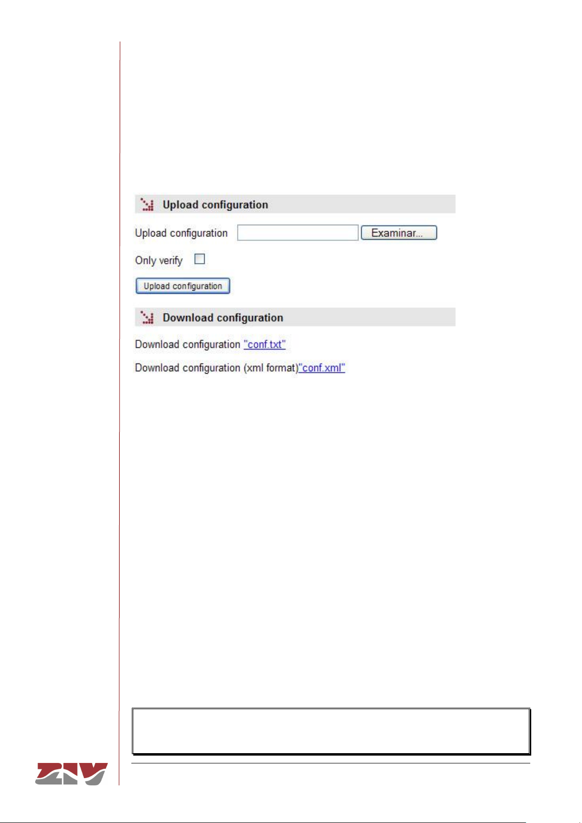
SIP-2
COMMUNICATION NODE TYPE SIP-2 100/145
USER GUIDE - Rev. 3 (January 2018)
5.20 CONFIGURATION FILE
The equipment configuration can be retrieved (Download) or uploaded (Upload) by means
of a text or XML file.
FIGURE 49 Options for uploading (Upload) or downloading (Download) the configuration file
5.20.1 Upload (from the computer to the equipment)
The user must select the file containing the configuration to be uploaded by pressing the
button Examine.
In order to only verify the configuration without upload it, the Only verify box must be
ticked.
Once the equipment has received the file, the system checks the file contents and verifies
that the variables are valid and that the values assigned to them comply with the existing
syntactic requirements. If errors are detected in the received file, irrespective of whether the
Only verify option is selected or not, the system automatically rejects all the information
received and indicates the error situation to the user.
If the received configuration is valid, it is indicated by the system to the user, and it is then
possible to continue (Continue button). When continue is selected, the configuration is
activated and stored.
When applying the new configuration, the system issues a warning due to the possible
loss of equipment access.
 Loading...