

ZIV MAS-2 User Manual

Communication solutions for power utilities
1/39
ZIV
Antonio Machado,78-80 08840
Viladecans, Barcelona-Spain
Tel.: +34 933 490 700
Fax: +34 933 492 258
Mail to: ziv@zivautomation.com
www.zivautomation.com
1U SHELF
TYPE MAS-2
WITH ASYNCHRONOUS PROGRAMMABLE MODEM
MAFP
Rev. 9 - January 2018
Communication solutions for power utilities
1U SHELF TYPE MAS-2
WITH ASYNCHRONOUS PROGRAMMABLE MODEM MAFP - Rev. 9 (January 2018)
2/39
SAFETY SYMBOLS
WARNING OR CAUTION:
This symbol denotes a hazard. Not following the indicated procedure,
operation or alike could mean total or partial breakdown of the
equipment or even injury to the personnel handling it.
NOTE:
Information or important aspects to take into account in a procedure,
operation or alike.

Communication solutions for power utilities
1U SHELF TYPE MAS-2
WITH ASYNCHRONOUS PROGRAMMABLE MODEM MAFP - Rev. 9 (January 2018)
3/39
TABLE OF CONTENTS
Page
1 INTRODUCTION 4
1.1 CONSTITUTION OF THE EQUIPMENT 4
1.2 TECHNICAL CHARACTERISTICS 5
1.2.1 Data transmission 5
1.2.2 Transmitter 5
1.2.3 Receiver 7
1.2.4 Data interface 9
1.2.5 Power supply 10
1.2.6 Environmental conditions 11
1.2.7 Other characteristics 11
2 OPERATING PRINCIPLE 19
2.1 TRANSMISSION 19
2.2 RECEPTION 19
2.3 GENERAL ALARM 20
2.4 TEST DEVICES 20
2.4.1 Line loop 21
2.4.2 Data loop 21
2.4.3 Continuous sending of test signals 22
2.5 MODEM BLOCKING 22
3 INSTALLATION 23
3.1 MECHANICAL AND ELECTRICAL CHARACTERISTICS 23
3.2 EXTRACTING AND INSERTING THE MODULE 23
3.3 EXTERNAL CONNECTION 24
4 COMMISSIONING 28
4.1 FRONT-PLATE ELEMENTS 28
4.1.1 CONFIGURATION microswitch 28
4.1.2 Signalling 30
4.1.3 Adjustments and test points 31
4.2 INTERNAL MICROSWITCH (MI2) 33
4.3 INTERNAL JUMPERS 35
4.4 ADJUSTMENTS 36
4.4.1 Transmit-level adjustment 36
4.4.2 Receive-level adjustment 36

Communication solutions for power utilities
1U SHELF TYPE MAS-2
WITH ASYNCHRONOUS PROGRAMMABLE MODEM MAFP - Rev. 9 (January 2018)
4/39
1 INTRODUCTION
The MAS-2 shelf made up of a MAFP module is an asynchronous narrowband modem with
frequency-shift keying (FSK) modulation for the transmission of data at speeds of 50 to
2400 Bd.
The technology used in the MAFP modem is based on digital signal processing and allows
the transmission speed and central frequency of each channel to be programmed by the
user. The transmission speed can be 50, 100, 200, 600, 1200 or 2400 Bd, whilst the central
frequency of each channel can be selected from between a wide range of values, including
those enumerated in recommendations R.35, R.37, R.38A and R.38B of the ITU-T. The
MAFP modem is also compatible with standard V.23 of the ITU-T.
Certain configurations of the MAFP modem allow it to share the available band with speech
frequencies and teleprotection signals. The speech band is limited by a frequency of 300 Hz
and by an upper frequency that is programmable between 2000 and 3400 Hz.
The data interface of the modem complies with specifications V.24 and V.28 of the ITU-T
and RS-232C of EIA.
The modem is equipped with test devices for a rapid operational check. These devices
make it possible to carry out loops and to generate test signals, which allow a DTE to be
emulated for the transmission of the logic levels "1", "0" or "1:0".
1.1 CONSTITUTION OF THE EQUIPMENT
The MAS-2 consists of a shelf that is one standard unit (s.u.) in height and 19” in width.
The MAFP module, incorporated in the shelf, is formed by a single-printed circuit board
where all the elements necessary for the transmission of a succession of binary data in a
voice-frequency channel are located. The main parts of the module are a transmitter block,
a receiver block as well as test and power-supply devices.

Communication solutions for power utilities
1U SHELF TYPE MAS-2
WITH ASYNCHRONOUS PROGRAMMABLE MODEM MAFP - Rev. 9 (January 2018)
5/39
In order to make commissioning easier, the front plate of the modem features elements
necessary for:
the adjustment and measurement of the transmission and reception levels,
the configuration of the modem such as the RTS-CTS delay selection, test selection, etc.,
the optical indication of the tests and logical signals of the interface.
the optical indication of the equipment status.
1.2 TECHNICAL CHARACTERISTICS
1.2.1 Data transmission
Data format
Binary, serial.
Asynchronous and anisochronous
Modulation
Frequency-shift keying (FSK)
Transmission speed
Programmable, by means of internal
microswitches, between 50, 100, 200, 600,
1200 or 2400 Bd
Transmission mode
Selectable by means of microswitch between:
Full-duplex, Half-duplex
Operation mode
By carrier detection in point-to-point links or
point-to-multipoint links
1.2.2 Transmitter
Central frequency
Programmable, by means of internal
microswitches, depending on the transmission
speed at which the modem is working at (see
Figure 2). Modems with other frequencies can
be supplied on demand

Communication solutions for power utilities
1U SHELF TYPE MAS-2
WITH ASYNCHRONOUS PROGRAMMABLE MODEM MAFP - Rev. 9 (January 2018)
6/39
Frequency shifting
From 30 Hz to 800 Hz, according to speed
Nominal bandwidth at 0.2 dB
- At 50 Bd/30 Hz: 121 Hz,140 Hz
(1)
- At 100 Bd/60 Hz: 123 Hz
- At 200 Bd/120 Hz: 245 Hz
- At 200 Bd/90 Hz: 185 Hz
- At 200 Bd/60 Hz: 126 Hz
- At 600 Bd/180 Hz: 715 Hz
- At 1200 Bd/400 Hz: 1405 Hz or 1435 Hz,
depending on whether the modem works in
superimposed band or not.
At 2400 Bd/800 Hz: 3016 Hz
Figure 3 to Figure 11 show, for each speed
and as an example, the response curve of the
transmission and reception filters at a
determined frequency
Line-frequency stability
<0.5 Hz across the whole temperature range
Transmission level
30 dBm to 0 dBm, over 600 .
Continuous adjustment in two ranges
Difference in levels between
line frequencies
<0.5 dB across the whole temperature range
Output impedance
Selectable by means of jumper between:
600 .
High impedance: >6 k up to 600 Hz.
>10 k between 600 Hz and 3800 Hz
Return loss
>18 dB between 420 and 3800 Hz
(1)
The only transmission speed for which the transmission and reception filters are not the same is 50 Bd.
The bandwidth of the reception filter is of 121 Hz whilst that of transmission is of 140 Hz.

Communication solutions for power utilities
1U SHELF TYPE MAS-2
WITH ASYNCHRONOUS PROGRAMMABLE MODEM MAFP - Rev. 9 (January 2018)
7/39
Balance
>60 dB between 420 and 3800 Hz
Insulation voltage
IEC 870-2-1 class 2.
(2)
1 kV
rms
/50 Hz/1 min
Impulse voltage
IEC 870-2-1 class 2.
(2)
2 kVp (1.2/50 s)
Fast transient bursts
IEC 870-2-1 level 3.
(2)
2 kVp
Damped oscillatory waves
IEC 870-2-1 level 2.
(2)
1 kVp
1.2.3 Receiver
Sensitivity
43 to 0 dBm.
Adjustment in three ranges
Nominal selectivity
for an attenuation of 40 dB
- At 50 Bd/30 Hz: 192 Hz
- At 100 Bd/60 Hz: 380 Hz
- At 200 Bd/120 Hz: 784 Hz
- At 200 Bd/90 Hz: 560 Hz
- At 200 Bd/60 Hz: 381 Hz
- At 600 Bd/180 Hz: 1600 Hz
- At 1200 Bd/400 Hz: 1472 Hz or 1902 Hz,
depending on whether the modem works in
superimposed band or not.
At 2400 Bd/800 Hz: 3192 Hz
Figure 3 to Figure 11 show, for each speed
and as an example, the response curve of the
transmission and reception filters at a
determined frequency
(2)
For waves applied between:
- Output terminals and power supply terminals.
- Output terminals and alarm relay terminals.
- Output terminals and ground terminals.

Communication solutions for power utilities
1U SHELF TYPE MAS-2
WITH ASYNCHRONOUS PROGRAMMABLE MODEM MAFP - Rev. 9 (January 2018)
8/39
S/N
12 dB for BER<10-4
Input impedance
Selectable by means of jumper between:
600 .
High impedance: >6 k up to 600 Hz.
>10 k between 600 Hz and 3800 Hz
Return loss
>18 dB between 420 and 3800 Hz
Balanced
>60 dB between 420 and 3800 Hz
Isochronous distortion
<3% for all speeds
Carrier detection
Generation of alarm at 14 dB below the
adjusted receive nominal level
Hysteresis
3 dB
Insulation voltage
IEC 870-2-1 class 2.
(3)
1 kV
rms
/50 Hz/1 min
Impulse voltage
IEC 870-2-1 class 2.
(3)
2 kVp (1.2/50 s)
Fast transient bursts
IEC 870-2-1 level 3.
(3)
2 kVp
Damped oscillatory waves
IEC 870-2-1 level 2.
(3)
1 kVp
(3)
For waves applied between:
- Input terminals and power supply terminals.
- Input terminals and alarm relay terminals.
- Input terminals and ground terminals.

Communication solutions for power utilities
1U SHELF TYPE MAS-2
WITH ASYNCHRONOUS PROGRAMMABLE MODEM MAFP - Rev. 9 (January 2018)
9/39
1.2.4 Data interface
Levels and impedance
In accordance with ITU-T Rec. V.28
Operation mode
In accordance with ITU-T Rec. V.24.
Available signals: TD, RD, RTS, CTS,
RLSD-Carrier detection (CD) and DSR
RTS-CTS delay
Selectable by means of microswitches. See
section 4, COMMISSIONING
Nominal propagation delay
- At 50 Bd: 23.5 ms
- At 100 Bd: 23 ms
- At 200 Bd: 11.5-21.5 ms depending on
the central frequency
- At 600 Bd: 7 ms
- At 1200 Bd: 14 ms (f0=1700 Hz), 32 ms
(f0=2940 Hz)
At 2400 Bd: 32 ms
Nominal delay in the CD signalling at the
appearance of the carrier
- At 50 Bd: 10 ms
- At 100 Bd: 10.5 ms
- At 200 Bd: 7.9-10.6 ms depending on
the central frequency
- At 600 Bd: 4.8 ms
- At 1200 Bd: 8 ms (f0=1700 Hz), 17.3 ms
(f0=2940 Hz)
At 2400 Bd: 17 ms
Nominal delay in the CD no-signalling at
the disappearance of the carrier
- At 50 Bd: 14 ms
- At 100 Bd: 12.5 ms
- At 200 Bd: 9.6-12.6 ms depending on
the central frequency
- At 600 Bd: 5.6 ms
- At 1200 Bd: 9 ms (f0=1700 Hz), 18.4 ms
(f0=2940 Hz)
At 2400 Bd: 18 ms

Communication solutions for power utilities
1U SHELF TYPE MAS-2
WITH ASYNCHRONOUS PROGRAMMABLE MODEM MAFP - Rev. 9 (January 2018)
10/39
Test devices
Line loop, data loop and permanent sending of
test signals, logical level "0", "1" or alternate
sequence of "0" and "1", generating signal
RTS internally.
The selection is carried out by means of
microswitches located on the front plate
Signalling
By optical indication:
- State of the logical signals of the interface
- Realization of some kind of test
- Realization of line and data loops
- Equipment status
- Indication that the modem is configured to be
used in Power-Line Carrier terminals or in
MAS-2 shelves.
By relay with voltage-free changeover contact:
- General alarm
Protection against electrostatic charges
IEC 870-2-1 level 4.
8 kV. Discharges by contact
1.2.5 Power supply
Input range
48 VDC 20%.
88-260 VDC or VAC
Insulation voltage
IEC 870-2-1 class 2.
1 kV
rms
/50 Hz/1 min
Impulse voltage
IEC 870-2-1 class 2.
2 kVp (1.2/50 s)
Fast transient bursts
IEC 870-2-1 level 3.
2 kVp

Communication solutions for power utilities
1U SHELF TYPE MAS-2
WITH ASYNCHRONOUS PROGRAMMABLE MODEM MAFP - Rev. 9 (January 2018)
11/39
Damped oscillatory waves
IEC 870-2-1 level 2.
1 kVp
Protection against overvoltages
Electronic PTC
Protection against polarity inversion
Permanent. By series diode
Maximum consumption
9 W
1.2.6 Environmental conditions
Operating
Temperature and humidity
In accordance with IEC 721-3-3 class 3K5.
5 C to +50 C
<95% non condensing
Mechanical
IEC 721-3-3 class 3M1
Storage
Maximum temperature
In accordance with IEC 721-3-1 class 1K5.
20 C to +70 C
Mechanical
IEC 721-3-1 class 1M1
Transportation
Maximum temperature
In accordance with IEC 721-3-2 class 1K5.
20 C to +70 C
Mechanical
IEC 721-3-2 class 2M1
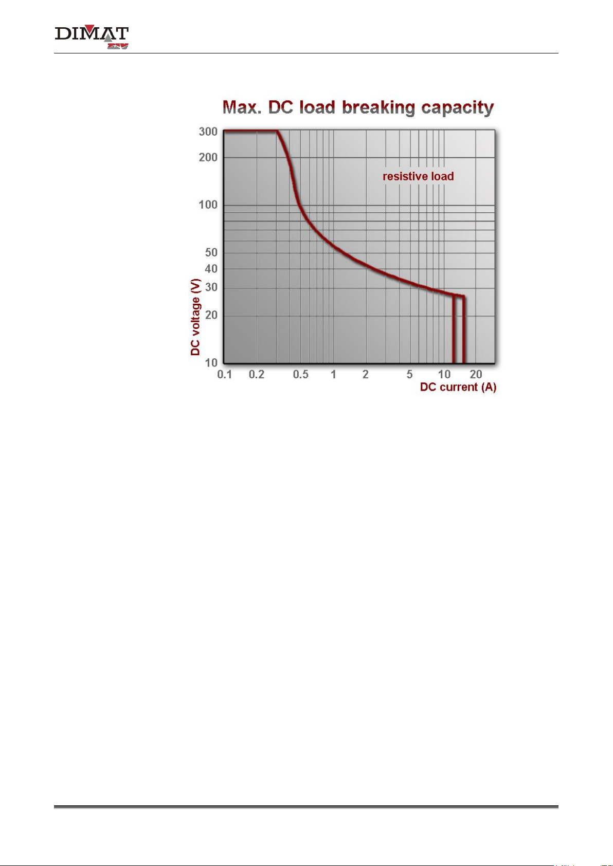
1.2.7 Other characteristics
Alarm relay
Changeover maximum current
3 A
Changeover maximum voltage
250 VAC, 150 VDC
Changeover maximum power
See Figure 1
Communication solutions for power utilities
1U SHELF TYPE MAS-2
WITH ASYNCHRONOUS PROGRAMMABLE MODEM MAFP - Rev. 9 (January 2018)
12/39
NOTE: 3A is the maximum current
Figure 1 DC voltage/ DC current
Insulation voltage
IEC 870-2-1 class 2.
1 kV
rms
/50 Hz/1 min
Impulse voltage
IEC 870-2-1 class 2.
2 kVp (1.2/50 s)
Maximum dimensions
483 x 44 x 326 mm.
See figure at the end of the manual
Weight
3.35 kg
 Loading...