

Page 1

Making the Smart Grid Real
1/158
ZIV
Antonio Machado,78-80
08840 Viladecans, Barcelona-Spain
Tel.: +34 933 490 700
Fax: +34 933 492 258
Mail to: [email protected]
www.zivautomation.com
DRA-2
UNIVERSAL COMMUNICATION NODE
USER GUIDE
Rev. 5 - January 2018
Page 2

DRA-2
DRA-2 UNIVERSAL COMMUNICATION NODE 2/158
USER GUIDE - Rev.5 (January 2018)
SAFETY SYMBOLS
WARNING OR CAUTION:
This symbol denotes a hazard. Not following the indicated procedure,
operation or alike, could mean total or partial breakdown of the
equipment or even injury to the personnel handling it.
NOTE:
Information or important aspects to take into account in a procedure,
operation or alike.
Page 3

DRA-2
DRA-2 UNIVERSAL COMMUNICATION NODE 3/158
USER GUIDE - Rev.5 (January 2018)
CONTENTS
Page
1 INTRODUCTION 6
1.1 INTELLIGENT NETWORKS 6
1.2 DRA-2 SOLUTION 6
1.3 DRA-2 INTERFACES 9
1.4 TECHNICAL SPECIFICATIONS 12
1.4.1 Characteristics of the DRA-2 with switch functionality 12
1.4.2 Characteristics of the DRA-2 with router functionality 12
1.4.3 Equipment management 12
1.4.4 Additional services 13
1.4.5 Accessories 13
1.4.6 Certifications 13
1.4.7 Equipment interfaces 14
1.4.7.1 GPRS (2G) interface characteristics 14
1.4.7.2 UMTS (3G) interface characteristics 14
1.4.7.3 MV BPLC (high speed) interface characteristics 15
1.4.7.4 MV SSPLC (long range) interface characteristics 15
1.4.7.5 Cable modem characteristics 15
1.4.8 Mechanical characteristics 16
1.4.9 Operating conditions 17
1.5 WARNINGS 18
1.5.1 Warnings before installing 18
1.5.2 Equipment safety considerations 18
2 MECHANICAL AND ELECTRICAL CHARACTERISTICS 19
3 LED SIGNALLING 25
Page 4

DRA-2
DRA-2 UNIVERSAL COMMUNICATION NODE 4/158
USER GUIDE - Rev.5 (January 2018)
Page
4 ACCESS TO THE EQUIPMENT 30
4.1 CONSOLE 30
4.2 HTTP SERVER 31
5 CONFIGURATION AND MANAGEMENT 33
5.1 GENERAL PARAMETERS 34
5.1.1 Equipment identification 35
5.1.2 Access control 35
5.1.3 Others 36
5.1.4 Syslog 36
5.2 ADMINISTRATION 37
5.3 LAN CONFIGURATION 38
5.3.1 Ports 38
5.3.2 VLAN 40
5.3.2.1 PVLAN function 41
5.3.3 PLC 43
5.4 WAN CONFIGURATION 46
5.4.1 Cell0 configuration 46
5.4.2 Tunnel configuration 57
5.4.3 CM configuration 60
5.5 QoS CONFIGURATION 61
5.5.1 QoS Layer 2 61
5.5.2 QoS Layer 3 64
5.6 ROUTING CONFIGURATION 67
5.6.1 Static routes 67
5.6.2 RIP Protocol 70
5.6.3 OSPF Protocol 72
5.7 FILTERING CONFIGURATION 76
5.8 NAT CONFIGURATION 78
5.9 DHCP RELAY CONFIGURATION 79
Page 5

DRA-2
DRA-2 UNIVERSAL COMMUNICATION NODE 5/158
USER GUIDE - Rev.5 (January 2018)
Page
5.10 DHCP SERVER CONFIGURATION 79
5.10.1 DHCP Server Profiles 80
5.10.2 DHCP Server Table 81
5.11 VRRP CONFIGURATION 81
5.12 VPN CONFIGURATION 85
5.13 NHRP CONFIGURATION 90
5.14 SNMP CONFIGURATION 93
5.15 STP 95
5.16 NTP CONFIGURATION 98
5.17 ACCESS CONFIGURATION 100
5.18 SECURITY CONFIGURATION 101
5.18.1 802.1x 10²
5.18.2 MAC list 104
5.19 REBOOT 105
5.20 CODE REFLASH 105
5.20.1 Backup 105
5.21 CONFIGURATION FILE 106
5.21.1 Upload (from the PC to the equipment) 106
5.21.2 Download (from the equipment to the PC) 107
6 STATISTICS 108
APPENDIX A
BIBLIOGRAPHY AND ABBREVIATIONS 117
APPENDIX B
DATA STRUCTURE IN CLI 122
APPENDIX C
WIDEBAND PLC COUPLERS 156
Page 6

DRA-2
DRA-2 UNIVERSAL COMMUNICATION NODE 6/158
USER GUIDE - Rev.5 (January 2018)
1 INTRODUCTION
1.1 INTELLIGENT NETWORKS
Intelligent Electrical Grids or "smartgrids" are known to everyone, and not just
specialists/technicians from the electrical sector. Nowadays, it is usual for the press to
publish articles about breakthroughs in this field. The diverse applications of "smartgrids"
are known to all; from demand management thanks to the new smart meters, to the
automation of distribution, the integration of renewable energies and the impact of electric
vehicles in future networks, etc.
To make those applications real, different technologies are required. Those technologies
include telecommunications, which play a fundamental role.
Electricity distribution companies have been deploying telecommunication networks to
provide remote connectivity to all their electrical substations. The new "smartgrid"
applications must provide safe connectivity for Transformation Centres. This aspect poses
an enormous challenge for the telecommunications areas of many electricity distribution
companies, mainly because of the large number of installations and the virtual lack of
connectivity in those installations at the present time.
The automation of transformation centres is therefore a necessary step on the way to
implementing "SmartGrids".
1.2 DRA-2 SOLUTION
To convert the new "smartgrid" applications into a reality, Transformation Centres need
more communications. But what type of information must the new telecommunications
equipment installed by us transmit?.
ZIV is in favour of the DRA-2 universal communication equipment for Medium Voltage
Transformation Centres.
Page 7

DRA-2
DRA-2 UNIVERSAL COMMUNICATION NODE 7/158
USER GUIDE - Rev.5 (January 2018)
The DRA-2 equipment is designed to transmit the services in a Transformation Centre to
higher levels in the electrical grid, through a wide range of interfaces:
Optical fibre
Medium Voltage Powerline Communications Technology (BPLC and SSPLC interfaces)
Cell technologies (GPRS/UMTS)
ADSL lines
Cable modem
The DRA-2 includes, as standard features, a serial maintenance interface, 6 Fast Ethernet
ports and 2 Gigabit Ethernet SFP bays.
The Fast Ethernet ports are usually used to provide service to the equipment in the
Transformation Centre (TC), such as PLC meter reading concentrators, remote telecontrol
units, protections, fault circuit indicators, cameras or IP phones.
The 2 Gigabit Ethernet SFP bays permit the inclusion of the DRA-2 communication node in
Optical Fibre ring-type topologies, or its use as a high-capacity uplink.
Clients should complete the equipment by selecting the different available interface options
(see section 1.3).
In addition to the switch function (L2), the DRA-2 has IPv4 route capacity (L3), which permits
various operation scenarios:
Option of operating as a switch for Ethernet, Gigabit Ethernet and PLC-MV (BPLC)
interfaces.
Routing functionality between two or more configured VLANs, with each VLAN being
made up of a set of local ports (Ethernet / Gigabit Ethernet / BPLC) and WAN interfaces
(GPRS / UMTS / ADSL).
The use of wireless WAN interfaces (GPRS / UMTS) as safety recourse (backup) for the
routing functionality described in the preceding section.
For the routing functions, the equipment supports the use of static (configured by the users)
and dynamic routing information, for which it has the standard RIP and OSPF routing
protocols.
Page 8

DRA-2
DRA-2 UNIVERSAL COMMUNICATION NODE 8/158
USER GUIDE - Rev.5 (January 2018)
The DRA-2 can be managed locally and remotely, through a console or through a built-in
web server, http or https, SSH connection and Telnet.
The DRA-2 also supports the SNMPv1, SNMPv2c and SNMP3 protocols, as well as other
protocols and services such as DHCP, NTP, TACACS+ and RADIUS.
The DR-2 stores internally an application software backup so that, in case of failure,
equipment operation by running the backup software is guaranteed.
FIGURE 1 DRA-2 solution
Page 9

DRA-2
DRA-2 UNIVERSAL COMMUNICATION NODE 9/158
USER GUIDE - Rev.5 (January 2018)
1.3 DRA-2 INTERFACES
One noteworthy aspect of the DRA-2 is its large variety of interfaces, which enables it to
provide a solution to the different topologies present in Transformation Centres. In some
Transformation Centres, PLC-MV technology is the only valid option, whereas in others
optical fibre or even ADSL (PSTN) can be used. Moreover, in cases where none of the
above options can provide sufficient communication, wireless interfaces or cable modem
(HFC modem) can be used.
FIGURE 2 Constitution of the DRA-2 node
The different basic and optional interfaces are integrated into the following three principal
modules (see FIGURE 2):
POWER SUPPLY, CENTRAL PROCESSING UNIT AND BASIC LAN INTERFACES.
This is the basic DRA-2 module. As the Central Processing Unit and element that
adapts and controls the peripherals, it carries out advanced Ethernet switching
functions (L2), routing functions, access protocols, flows and congestion controls and
advanced traffic management functions.
It has 6 Fast Ethernet ports in a 10/100Base-Tx configuration.
It has also 2 receptacles for Gigabit Ethernet SFP transceivers.
The power supply is included in the basic module and there are two versions: the first
for use with continuous current of 48 VDC, while the second admits the use of
alternating current and continuous current, but in this case, from a voltage range of
over 80 VDC. Both versions generate the internal supply voltages based on the input
voltage, and have several input filters for protective purposes. The power supply is
protected against reverse polarity.
Page 10

DRA-2
DRA-2 UNIVERSAL COMMUNICATION NODE 10/158
USER GUIDE - Rev.5 (January 2018)
SERVICE CONSOLE AND WAN INTERFACES OPTION (GPRS/UMTS/ADSL)
This module has a connector known as SRV for accessing the equipment through the
console. That connector is always included as a basic element.
It may also have WAN interfaces, and users must select one of the following options:
- 1 GPRS (2G) with 1 SIM and 1 SMA antenna connector
- 1 GPRS (2G) with 2 SIMs and 1 SMA antenna connector
- 2 GPRS (2G) with 2 SIMs and 2 SMA antenna connectors
- 1 GPRS (2G) with 1 SIM and 1 SMA antenna connector + 1 ADSL (on request)
- 1 ADSL (on request)
- 1 GPRS (2G) with 1 SIM and 1 SMA antenna connector + 1 UMTS with 1 SIM and 1
SMA antenna connector (on request)
- 1 UMTS (3G) with 1 SIM and 1 SMA antenna connector + 1 ADSL (on request)
- 1 UMTS (3G) with 1 SIM and 1 SMA antenna connector
- 1 UMTS (3G) with 2 SIMs and 1 SMA antenna connector
PLC-MV, ADDITIONAL LAN INTERFACES OR OTHER OPTIONS
This module may be prepared for different types of interface. Users should select one
of the following options:
- 1 high speed BPLC interface
- 2 high speed BPLC interfaces
- 1 low speed SSPLC interface (in the process of being developed)
- 2 low speed SSPLC interfaces (in the process of being developed)
- 1 cable modem (non-compatible with PLC option)
- 2 additional Fast Ethernet interfaces (100Base-Tx or 100Base-Fx) (in the process of
being developed)
- 1 RS-232 serial interface (in the process of being developed) (not valid with 1 ADSL
or 2 PLCs)
- 1 RS-485 serial interface (in the process of being developed) (not valid with 1 ADSL
or 2 PLCs)
- 1 optical serial interface (in the process of being developed) (not valid with 1 ADSL
or 2 PLCs)
- 1 PLC meter reading concentrator (in the process of being developed)
Page 11

DRA-2
DRA-2 UNIVERSAL COMMUNICATION NODE 11/158
USER GUIDE - Rev.5 (January 2018)
WAN interfaces allow users to utilise the services of public operators and are a very useful
alternative, in view of their geographical coverage and the fact that they are easy to put into
operation.
The cable modem is the necessary device to access the services of the cable operators.
The MV PLC is a good option for transmitting information from the different Transformation
Centres to a Main Substation. There are two types of interface for Powerline
Communications through the Medium voltage network:
A high speed BPLC interface, designed especially for urban environments in which mid-
distance levels must be covered, since the transformation centres are very close to each
other.
A low speed SSPLC interface which allows much greater distances to be covered,
designed for rural environments where the quantity of information to be transmitted is
much smaller and priority is given to covering longer distances and accessing more
remote areas.
For injecting the PLC signal in the Medium Voltage networks, Wideband PLC couplers are
used, adapted to that technology, and to the different installation sites. The available range
is described in APPENDIX C.
Page 12

DRA-2
DRA-2 UNIVERSAL COMMUNICATION NODE 12/158
USER GUIDE - Rev.5 (January 2018)
1.4 TECHNICAL SPECIFICATIONS
1.4.1 Characteristics of the DRA-2 with switch functionality
➢ Port speed automatic detection.
➢ STP and RSTP for resolving loops in the network and operation in rings.
➢ VLANs management per port.
➢ QoS management per VLAN (802.1p).
➢ Broadcast and Multicast (Broadcast Storm Control) traffic limitation.
➢ MAC access control lists and 802.1x user authentication.
➢ Level 2 switching between Ethernet and PLC-MV environment in the event of having a
Medium Voltage BPLC interface.
1.4.2 Characteristics of the DRA-2 with router functionality
➢ Routing, filtering, NAT, firewall and tunneling capabilities.
•
Up to 6 simultaneous IPSec tunnels with DMVPN (Dynamic Multipoint VPN) and
NHRP (Next Hop Resolution Protocol) support.
•
RIP and OSPF routing protocols.
•
VRRP redundancy protocol.
➢ Assignment of Quality of Service, and layer 3/4 Quality of Service management. Priority
management levels are the following:
•
Quality per origin and/or destination IP address.
•
Quality per type of traffic (DSCP or TOS) and service (protocol and port).
➢ Models having 2 wireless interfaces support the establishment of two IP links
simultaneously, both performing as active backup, with fast switching, or load balance.
1.4.3 Equipment management
➢ Local and remote access through a console or through a built-in web server, http or
https, SSH connection and Telnet.
➢ The wireless interface model allows for manage through data calls.
Page 13

DRA-2
DRA-2 UNIVERSAL COMMUNICATION NODE 13/158
USER GUIDE - Rev.5 (January 2018)
1.4.4 Additional services
➢ SNMP agent
➢ DHCP server and client
➢ NTP server and client
➢ TACACS+ client
➢ RADIUS client
➢ DHCP Relay
➢ PVLAN (RFC 5517)
1.4.5 Accessories
➢ SFP modules.
➢ Antenna cables.
➢ Antennas.
➢ Ethernet Cables.
➢ Optical fibre pigtails.
➢ PLC coaxials.
➢ Wideband PLC couplers (see Appendix C).
1.4.6 Certifications
➢ CE.
➢ Designed for industrial applications.
➢ Designed for Electrical Substations.
Page 14

DRA-2
DRA-2 UNIVERSAL COMMUNICATION NODE 14/158
USER GUIDE - Rev.5 (January 2018)
1.4.7 Equipment interfaces
➢ Basic interfaces:
•
6 Fast Ethernet ports in 10/100Base-Tx configuration.
•
2 Gigabit Ethernet SFP ports.
•
1 service console.
➢ The interfaces provided by the available options*:
•
GPRS (2G) / UMTS (3G) and ADSL (on request)
•
BPLC
•
SSPLC (being developed)
•
cable modem (DOCSIS/EuroDOCSIS 1.0/1.1/2.0)
•
Fast Ethernet (100Base-Tx or 100Base-Fx) (being developed)
•
RS-232, RS-485, optical serie (being developed)
1.4.7.1 GPRS (2G) interface characteristics
➢
Quad band: 850/900/1800/1900MHz.
•
Class 4 (+33dBm ±2dB) for EGSM850
•
Class 4 (+33dBm ±2dB) for EGSM900
•
Class 1 (+30dBm ±2dB) for GSM1800
•
Class 1 (+30dBm ±2dB) for GSM1900
1.4.7.2 UMTS (3G) interface characteristics
➢ UMTS/HSDPA: Dual band, 900/2100MHz
➢ GSM/GPRS/EDGE: Dual band, 900/1800MHz
•
Class 4 (+33dBm ±2dB) for EGSM900
•
Class 1 (+30dBm ±2dB) for GSM1800
•
Class E2 (+27dBm ± 3dB) for GSM 900 8-PSK
•
Class E2 (+26dBm +3 /-4dB) for GSM 1800 8-PSK
•
Class 3 (+24dBm +1/-3dB) for UMTS 2100, WCDMA FDD BdI
•
Class 3 (+24dBm +1/-3dB) for UMTS 900,WCDMA FDD BdVIII
*
See list of combinations permitted in section 1.3, DRA-2 interfaces.
Page 15

DRA-2
DRA-2 UNIVERSAL COMMUNICATION NODE 15/158
USER GUIDE - Rev.5 (January 2018)
1.4.7.3 MV BPLC (high speed) interface characteristics
➢ Frequency range of 2 to 30 MHz.
➢ 200 Mbit/s* channel rate.
➢ 150 Mbit/s* user max. rate.
➢ AES encryption of 128 bits.
➢ Flexibility in suppressing certain frequencies to prevent interference with other services.
➢ OFDM modulation with 1155 useful carriers.
➢ 1024/256/64/16/8 QAM, QPSK, BPSK, ROBO modulation (DBPSK basic/robust
modulation) – independently applied to each carrier.
➢ Output power of between 1 and 10 W
➢ Range of up to 1 km*.
1.4.7.4 MV SSPLC (long range) interface characteristics
➢ Frequency range of 2 to 10 MHz.
➢ 128 kbit/s† speed.
➢ Direct-Sequence Spread Spectrum (DSSS) Modulation.
➢ Output power of between 1 and 10 W
➢ Distances up to 5 km*.
1.4.7.5 Cable modem characteristics
➢ Protocol support:
•
DOCSIS/EuroDOCSIS 1.0/1.1/2.0
•
SNMP v1, v2c, v3
➢ Connector: F-type female 75 Ω RF
➢ Receiver
•
Demodulation: 64/256 QAM
•
Maximum speed: 38 Mbit/s (64 QAM) / 43 Mbit/s (256 QAM) DOCSIS
•
Frequency range: 108 ÷ 860 MHz (EuroDOCSIS)
•
Signal level: -13 ÷ 17 dBmV (EuroDOCSIS)
•
Input return loss: >6 dB EuroDOCSIS (108 ÷ 860 MHz)
*
There is a trade-off between transmission rate, distance and SNR needed in the receiver.
†
There is a trade-off between transmission rate, distance and SNR needed in the receiver.
Page 16

DRA-2
DRA-2 UNIVERSAL COMMUNICATION NODE 16/158
USER GUIDE - Rev.5 (January 2018)
➢ Transmitter
•
Modulation:
TDMA: QPSK, 8QAM, 16QAM, 32QAM, 64QAM
S-CDMA: QPSK, 8QAM, 16QAM, 32QAM, 64QAM,128QAM
•
Maximum speed:
320, 640, 1280, 2560, 5120 kbit/s (QPSK)
640, 1280, 2560, 5120, 10240 kbit/s (16QAM)
•
Frequency range: 5 ÷ 65 MHz (EuroDOCSIS)
•
Bandwidth:
TDMA: 200, 400, 800, 1600, 3200 and 6400 kHz
S-CDMA: 1600, 3200 and 6400 kHz
•
Signal level:
TDMA: +8 ÷ +54 dBmv (32QAM, 64QAM)
+8 ÷ +55 dBmv (8QAM, 16QAM)
+8 ÷ +58 dBmv (QPSK)
S-CDMA: +8 ÷ +53 dBmv (all modulations)
•
Output level of CM can be automatically controlled by CMTS through power ranging
(1dB steps)
•
Output return loss: >6 dB EuroDOCSIS (5 ÷ 65 MHz)
➢ CPEs
•
Maximum number of CPEs: 32 (32 MAC addresses)
•
Filtering:
LLC: 16
IP: 32
•
Frequency searching
Frequency cache: 4 entries
Channel plan: 8 MHz, 1 MHz, 0.25 MHz (EuroDOCSIS)
➢ SIDS
•
Number of SIDs: 16
➢ Management
•
MIBs: MIB II, MCNS MIB
1.4.8 Mechanical characteristics
➢
Dimensions Height: 140 mm; Width: 220 mm; Depth: 94 mm.
For more mechanical and electrical details about the connectors see chapter 2,
Mechanical and electrical characteristics.
➢
Weight 1 Kg.
➢ DIN rail installation (EN 50022, BS 5584, DIN 46277-3)
➢ IP protection level: IP 2xB
➢ Material: Grey (RAL 7024) Lexan 920 fire-resistant (UL 94 V0) plastic
Page 17

DRA-2
DRA-2 UNIVERSAL COMMUNICATION NODE 17/158
USER GUIDE - Rev.5 (January 2018)
1.4.9 Operating conditions
➢
Power supply: 16-75 Vdc (48 Vdc nominal) or multirange (80-360 Vdc, 80-260 Vac).
➢
Temperature and humidity: from -20ºC to +70ºC and relative humidity not greater than
95%, in accordance with IEC 721-3-3 class 3K5 (climatogram 3K5).
➢
Power consumption: Max. 15 W.
➢
Electrical safety: In accordance with EN 60950 standard.
➢
R.F. emissions: In accordance with EN 55022 standard.
➢
Immunity to electrostatics discharges: In accordance with UNE-EN 61000-4-2 standard.
➢
Immunity to R.F. permanent electromagnetic fields: In accordance with UNE-EN 610004-3 standard.
Page 18

DRA-2
DRA-2 UNIVERSAL COMMUNICATION NODE 18/158
USER GUIDE - Rev.5 (January 2018)
1.5 WARNINGS
1.5.1 Warnings before installing
1. The installation of the DRA-2 in Electrical Substations or Secondary
Substations is generically subject to the fulfilment of all the safety measures
and prevention of risks established for this type of work by the electricity
company that will use these devices and the Safety standards (EN 50110).
2. In order to install and handle the DRA-2 the following points must be
complied with:
- Only qualified personnel appointed by the electricity company that owns
the installation should carry out the installation and handling of the DRA-2.
- The environment in which it is to operate should be suitable for the DRA-2,
fulfilling all the conditions indicated in section 1.4.9.
3. ZIV will not accept responsibility for any injury to persons, installations or third
parties, caused by the non-fulfilment of points 1 and 2.
1.5.2 Equipment safety considerations
1. The terminal contains components sensitive to static electricity, the following
must be observed when handling it:
- Personnel appointed to carry out the installation and maintenance of the
DRA -2 must be free of static electricity. An anti-static wristband and/or
heel connected to earth should be worn.
- The room housing the DRA-2 must be free of elements that can generate
static electricity. If the floor of the room is covered with a carpet, make sure
that it is anti-static.
2. ZIV will not accept responsibility for any damage to the equipment caused by
the non-fulfilment of point 1.
Page 19

DRA-2
DRA-2 UNIVERSAL COMMUNICATION NODE 19/158
USER GUIDE - Rev.5 (January 2018)
2 MECHANICAL AND ELECTRICAL CHARACTERISTICS
The diverse elements comprising the DRA-2 communication node are supplied in a
high-resistance, epoxy plastic box, ready for DIN rail mounting.
The general dimensions of the equipment in mm are shown in FIGURE 3. The element for
fastening the equipment to the DIN rail is at the bottom of the box (see FIGURE 4).
FIGURE 3 General dimensions in mm of the DRA-2 equipment
Page 20

DRA-2
DRA-2 UNIVERSAL COMMUNICATION NODE 20/158
USER GUIDE - Rev.5 (January 2018)
FIGURE 4 Detail of the DIN rail fastening element
Page 21

DRA-2
DRA-2 UNIVERSAL COMMUNICATION NODE 21/158
USER GUIDE - Rev.5 (January 2018)
The DRA-2 is powered with a nominal voltage of 48 Vdc (the admitted voltage range is
between 16 and 75 Vdc) or allows DC and AC supply-voltage operation (80-360 Vdc, 80260 Vac), through the connector shown in FIGURE 5.
The female connector supplied with the equipment is suitable for rigid or flexible conductors
of up to 2.5 mm2.
FIGURE 5 Power supply connector
Page 22

DRA-2
DRA-2 UNIVERSAL COMMUNICATION NODE 22/158
USER GUIDE - Rev.5 (January 2018)
The basic elements of the equipment consist of 6 Fast Ethernet 10/100Base-Tx ports and 2
SFP Gigabit Ethernet ports, having the bays a protective cap (see FIGURE 6).
FIGURE 6 Basic Ethernet connectors
The DRA-2 has also a maintenance connector, identified as SRV, see FIGURE 7, for
accessing the equipment through a console. The connector has a protective cap. The
electrical characteristics of the connector are shown in the following table.
SRV CONNECTOR
Interface type
ITU-T V.24/V.28 (EIA RS-232)
Connector
DB9 female
Data
Asynchronous
Speed
115200 bit/s
Protocol
CLI (system console)
Page 23

DRA-2
DRA-2 UNIVERSAL COMMUNICATION NODE 23/158
USER GUIDE - Rev.5 (January 2018)
FIGURE 7 Maintenance connector
When the equipment is fitted with WAN (GPRS/UMTS) interfaces, it has up to two SMA
connectors for GSM/GRPS antennas and up to two slots for housing SIM cards, see
FIGURE 8. Both SIMs can be activated simultaneously by two different operators or be
used in dual SIM operation, that is to say, with one SIM as the primary one and the other as
the secondary or back-up one.
FIGURE 8 Detail of SMA antenna connector and slot for housing SIM card in WAN (GPRS/UMTS)
interface
Page 24

DRA-2
DRA-2 UNIVERSAL COMMUNICATION NODE 24/158
USER GUIDE - Rev.5 (January 2018)
When the equipment is fitted with PLC-MV HPAV interfaces (see FIGURE 9) it has up to
two BNC connectors.
FIGURE 9 Detail of PLC-MV (BPLC) interfaces
When the equipment, instead of PLC-MV interfaces, has the cable modem interface, see
FIGURE 10, it has a F-type female connector (75 Ω RF).
FIGURE 10 Detail of cable modem interface
Page 25

DRA-2
DRA-2 UNIVERSAL COMMUNICATION NODE 25/158
USER GUIDE - Rev.5 (January 2018)
3 LED SIGNALLING
The front of the DRA-2 equipment has two basic LEDs and several specific LEDs
associated with the WAN (GPRS/UMTS) and/or MV-PLC interfaces.
FIGURE 11 shows a view of the DRA-2 with WAN (GPRS/UMTS) interfaces as a main
option, while FIGURE 12 shows DRA-2 equipment with PLC-MV interfaces as a main
option.
Access to the LEDs associated with the basic Ethernet interfaces is possible after raising
the plastic cover. FIGURE 13 shows a detail of those LEDs.
FIGURE 11 DRA-2 with WAN (GPRS/UMTS) or cable modem (HFC modem) interfaces
ON LED
Red. It is permanently lit when the
equipment is powered with an external
power-supply voltage.
Srv LED
Amber. It flashes when there is emission or
reception activity by the SRV serial service
interface.
Page 26

DRA-2
DRA-2 UNIVERSAL COMMUNICATION NODE 26/158
USER GUIDE - Rev.5 (January 2018)
Net A LED
Green. It stays on when the wireless
interface (GPRS/UMTS) has been
registered in the operator network.
Session A LED
Amber. It stays on when the operator
session has been established for the
wireless interface (GPRS/UMTS)
designated as 1.
Cvrg A LED
Three-coloured. It stays on, indicating the
coverage level.
Green: signal coverage is good.
Amber: signal coverage is average.
Red: insufficient coverage.
SIM A / SIM B LED
(STATUS of cable modem)
Two-coloured. It stays on, indicating which
of the two SIMs is in use.
Green: SIM A is in use.
Red: SIM B is in use.
It is the STATUS LED for a cable modem
(HFC modem). Green. It flashes during the
registration and authentication phase. It is
permanently lit when the indicated phases
are finished appropriately.
Page 27

DRA-2
DRA-2 UNIVERSAL COMMUNICATION NODE 27/158
USER GUIDE - Rev.5 (January 2018)
Link / Act Port 7 LED
(UPSTREAM of cable modem)
Green. It stays on when the link is
established correctly and flashes in the case
of emission or reception activity in the PLC
1 interface.
It is the UPSTREAM LED for a cable
modem (HFC modem). Green. It flashes
during the ranging phase with the CMTS. It
is permanently lit when the upstream
channel is connected.
Link / Act Port 8 LED
(ETHER of cable modem)
Green. It stays on when the link is
established correctly and flashes in the case
of emission or reception activity in the PLC
2 interface.
It is the ETHER LED for a cable modem
(HFC modem). Green. It flashes when the
CM sends/receives traffic.
Non silk-screen printed LED
(DOWNSTREAM of cable modem)
It is the DOWNSTREAM LED for a cable
modem (HFC modem). Amber. It flashes
during the connecting phase of the
downstream channel. It is permanently lit
when the channel is connected.
The DOWNSTREAM LED would flash in a regular phase, and the rest would be off, in the
case of a cable modem (HFC modem). Next, the DOWNSTREAM LED would be lit
permanently, and the UPSTREAM LED would flash. Once the DOWNSTREAM and
UPSTREAM LEDs are lit permanently, the STATUS LED would flash. Once the STATUS
LED is lit permanently, the ETHER LED would indicate the activity.
Page 28

DRA-2
DRA-2 UNIVERSAL COMMUNICATION NODE 28/158
USER GUIDE - Rev.5 (January 2018)
FIGURE 12 DRA-2 with PLC-MV (BPLC) interfaces
PLC Act. LED
Green. It stays on when the PLC interface is
operating in the Master mode. When the
interface is operating in Slave mode, it
displays the activity on the interface.
While the device is initialising, it flashes in
synchrony with the PLC State LED.
If the interface is disabled (device in power
down), it goes off.
PLC State LED
Amber. It stays on when the PLC device is
functioning correctly. It blinks with a
frequency of 50% when the device is
initialising and flashes briefly when the
interface is disabled (device in power down).
Page 29

DRA-2
DRA-2 UNIVERSAL COMMUNICATION NODE 29/158
USER GUIDE - Rev.5 (January 2018)
FIGURE 13 LEDs associated with the basic Ethernet interfaces
Link/Act. LED
Two-coloured. There is one LED per
interface. It stays on when the link is
established correctly and flashes in the case
of emission or reception activity in the
interface. It lights up in green at 100 Mbit/s
and in amber at 10 Mbit/s.
Duplex/Col. LED
Amber. There is one LED per
10/100Base-Tx interface. It stays on when
the transmission is Full-duplex and goes off
when the transmission is Half-duplex. It
flashes in the case of collision.
SFP Presence LED
Amber. There is one LED per SFP Gigabit
Ethernet interface. It stays on when an SFP
transceiver is in the physical receptacle.
Page 30

DRA-2
DRA-2 UNIVERSAL COMMUNICATION NODE 30/158
USER GUIDE - Rev.5 (January 2018)
4 ACCESS TO THE EQUIPMENT
The DRA-2 can be managed locally and remotely, through a console or through a built-in
web server. The server operates with the http or https protocol.
4.1 CONSOLE
The equipment provides a user console application called CLI (see APPENDIX B),
accessible through the SRV connector, a standard DB9 female connector in DCE mode
that operates at 115200 bit/s, with 8-bit characters, without parity and with a stop bit.
The system makes a distinction between upper and lower case characters.
Depending on the user identity, the user console provides full access to all the equipment
configuration data.
The console has a small help section about the available commands that is obtained by
executing the help command.
The data are grouped virtually into directories and subdirectories. To browse through the
directories the cd (change directory) command is used. The value of an individual data
item or a group of data is obtained in response to a get command, indicating the specific
data item or giving the value of all the data located in the current directories and
subdirectories. To establish a new value, it is necessary to execute the set command,
indicating the parameter to be changed and then the desired value; if the value to be
configured is not provided, the system will explicitly request it.
The data stored in table form, identified by the inclusion in the variable name of the symbol
[], have specific commands for adding and removing rows, which are add and remove
respectively. To query or establish the value of the data in one row, the row identifier must
be included between square brackets in the get or set command.
Page 31

DRA-2
DRA-2 UNIVERSAL COMMUNICATION NODE 31/158
USER GUIDE - Rev.5 (January 2018)
Changes made with the set command are not operative merely because they have been
executed. Effective, immediate use of the changes made is achieved by executing the
Apply command. On the contrary, the Save commands entails storing the changes
made permanently, without requiring their immediate use, but applied in the case of an
initialisation.
In this way, the changes are implemented as an operating procedure through the Apply
command, and after checking that the behaviour is correct, it is saved using the Save
command. Consequently in the case of obtaining undesirable results, it is always
possible to eliminate the Save command and reboot the equipment to recover the
previous status, even in the case that the changed activated lead to the user not being
able to obtain access.
Access can also be obtained to the console remotely through SSH connection and Telnet.
4.2 HTTP SERVER
The HTTP server included provides access to the HTML pages giving access to all the
configuration data.
The procedures for the effective configuration of the parameters are identical, that is to
say, it is necessary to execute the Apply command and/or the Save command, as
indicated in the section on using the console, but before executing these commands, the
system must be informed that the data have been changed through the Send command
(the button is present in all the HTML pages).
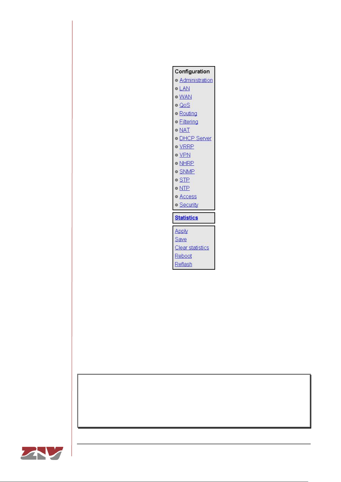
The Apply and Save commands are at the bottom of the tree menu and are only visible
when the user profile has administration rights. The commands indicated are shown on
FIGURE 14.
Page 32
DRA-2
DRA-2 UNIVERSAL COMMUNICATION NODE 32/158
USER GUIDE - Rev.5 (January 2018)
FIGURE 14 HTML page tree menu
For information about the Reboot and Reflash commands see sections 5.19 and 5.20,
respectively.
The Apply, Save and Reboot commands request confirmation of the operation from the
user before it is actually executed.
In the HTML pages the commands for adding and removing elements from the tabulate
data are explicitly shown as buttons labelled Add and Delete, located on each of the objects
that use them.
The factory IP address of the equipment is 192.168.0.1, meaning it is possible to access
the HTTP server to configure it from the very start (see chapter 5).
It should be borne in mind that if the IP address is changed, the IP address of the client
equipment must also be changed accordingly.
Page 33

DRA-2
DRA-2 UNIVERSAL COMMUNICATION NODE 33/158
USER GUIDE - Rev.5 (January 2018)
5 CONFIGURATION AND MANAGEMENT
Configuration and management of the DRA-2 is performed through the console and
through access to the equipment HTML pages.
All the parameters controlling the equipment operation are described below in detail, using
the real HTML pages, as shown in the auxiliary graph.
Whenever changes are made, regardless of whether they are made through the console
or the HTTP server, the equipment must be informed what is to be done with them.
There are two options:
- the first is to execute the Apply command, which entails the immediate use of the
changes made.
- the second is to execute the Save command, which means that the changes will be
operative once the equipment is rebooted.
If accessing through the HTTP server, after making the changes and before executing
Apply or Save, the Send button must be pushed to allow the equipment to obtain the
new desired values.
If executing the Apply command, if the changes are required to be permanent, the Save
command must also be executed.
The only exceptions are changes affecting the SNMP configuration. Changes made to
the SNMP agent configuration will only be active after RESETTING the equipment. The
Apply command is not sufficient, and so the changes must previously be saved using
the Save command before requesting the re-initialisation.
Page 34
DRA-2
DRA-2 UNIVERSAL COMMUNICATION NODE 34/158
USER GUIDE - Rev.5 (January 2018)
5.1 GENERAL PARAMETERS
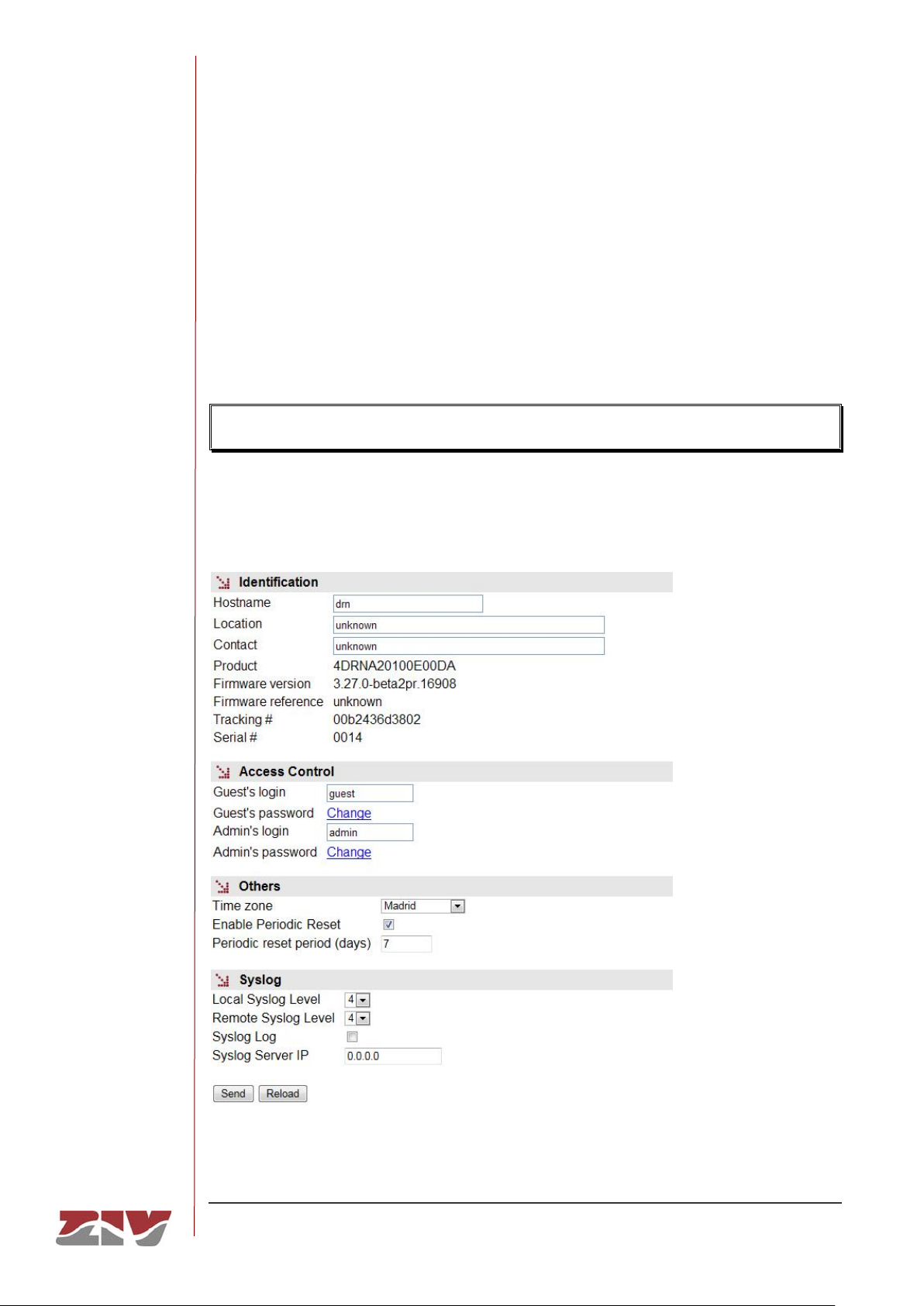
The general parameters are grouped on the first page, see FIGURE 15, which is shown
when the DRA-2 validates the user identity.
In addition to the configuration parameters, which will be described in the following
sections, as shown in the figure, the system provides information about the equipment
software, that is to say, version being executed, and equipment hardware, that is to say,
serial and tracking number.
The tree menu is permanently located on all the pages used by the HTTP server.
FIGURE 15 Main HTML page
Page 35
DRA-2
DRA-2 UNIVERSAL COMMUNICATION NODE 35/158
USER GUIDE - Rev.5 (January 2018)
5.1.1 Equipment identification
The identification zone has three parameters; the equipment name (hostname), its location
(location) and the contact data of the responsible person or company (contact). At least
one string of text is required, with at least one character.
The hostname is used automatically as a prompt value on the console.
The identification parameters coincide with those assigned with the same name in the
SNMP data.
5.1.2 Access control
Access control allows the user logins and associated passwords to be determined for the
two pre-established profiles: guest and admin.
The guest profile can only access query operations. On the contrary, the admin. profile has
access to all the system configuration data.
As summarised in TABLE 1, the default values of these parameters are guest and admin
as the logins, with passwd01 and passwd02 being the respective passwords.
It should be borne in mind that the system makes a distinction between upper and lower
case characters.
TABLE 1 System default access codes
Login
Password
Guest profile
guest
passwd01
Admin. profile
admin
passwd02
It is highly recommended to change at least the password of the admin. profile when
executing the first configuration in each equipment.
It is advisable to store the new password in some type of register as, should the new
password be forgotten, it is not possible to access the web server.
Page 36

DRA-2
DRA-2 UNIVERSAL COMMUNICATION NODE 36/158
USER GUIDE - Rev.5 (January 2018)
5.1.3 Others
This section deals with three parameters. The first of them establishes the hour zone in
relation to UTC.
The second parameter, Enable periodic reset, allows users to indicate whether they want
to reboot the equipment automatically every so often. This is established in days through
the last parameter, Periodic reset period.
5.1.4 Syslog
This section deals with four parameters. The first of them, Local Syslog Level, establishes
the maximum level of severity which is stored in the local Log. The range admitted is
between 1 and 8. The default value is 4.
The levels involve storing all information tagged with a level equal to or lower than the level
specified.
The levels are:
Level
Description
Emergency: Level 1
Multiple apps/servers/sites. This level should not be used by
applications.
Alert. Level 2
Should be corrected immediately. An example might be the
loss of the primary ISP connection.
Critical. Level 3
May be used to indicate a failure in the system’s primary
application.
Error. Level 4
An application has exceeded it file storage limit and attempts
to write are failing.
Warning. Level 5
May indicate that an error will occur if action is not taken, For
example a non-root file system has only 2GB remaining.
Notice. Level 6
Events that are unusual but not error conditions.
Informational. Level 7
Normal operational messages -no action required. Example
an application has started, paused or ended successfully.
Debugging. Level 8
Info useful to developers for debugging the application.
Page 37
DRA-2
DRA-2 UNIVERSAL COMMUNICATION NODE 37/158
USER GUIDE - Rev.5 (January 2018)
The second parameter, Remote Syslog Level, establishes the maximum severity level to
be sent to the Remote Syslog server. The range admitted is between 1 and 8. The default
value is 4. See information about the levels in the previous parameter.
The third parameter, Syslog Log, is a Checkbox control. By default, it is NOT selected,
which means that a remote server is configured and the traces are NOT stored in the local
Log. When the control is selected, the traces are sent to the remote server and are also
stored in the local Log with the corresponding severity level.
The last parameter, Syslog Server IP, establishes the IP address of the Remote Syslog
server to which the information is sent.
The system can order the selective activation/desactivation of log information associated
to some operating blocks (see command log).
Through CLI it is possible to consult the local log files other than the current one (see
command show).
5.2 ADMINISTRATION
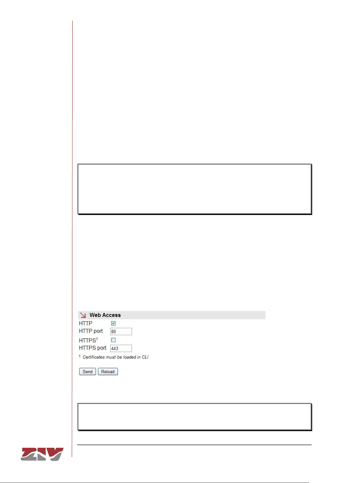
The equipment has an integrated http server for management purposes. The server
supports the http and the HTTPS protocols, and users can selectively enable their use and
the respective port.
FIGURE 16 Administration menu
The procedure for the installation of the certificates is described in section B.4 of
Appendix B, Data structure in CLI.
Page 38
DRA-2
DRA-2 UNIVERSAL COMMUNICATION NODE 38/158
USER GUIDE - Rev.5 (January 2018)
5.3 LAN CONFIGURATION
DRA-2 can operate built-in switch in two different modes that cannot be used
simultaneously. These modes are:
Switch function as single or multiple independent devices, and interfaces assigned to
one of those devices individually.
Switch device running PVLAN (RFC 5517). In this case, user must select which VLAN
will act as Primary, and which one will act as Isolated (Secondary). Interfaces keep
being assigned individually to different VLANs.
Default behaviour is to operate switch as usual, an enable object is provided to activate
PVLAN function.
The LAN menu contains three submenus: Ports, VLAN and PLC. Their functionalities are
described below.
5.3.1 Ports
This submenu permits the configuration of the operating parameters of the Ethernet ports in
the equipment and that of the two ports associated with the BPLC interfaces if these are
present, and the assigning of each port to one of the VLANs defined in the equipment
(consult section 5.3.2 first).
The number of ports shown in the submenu depends on the real number of ports in the
equipment. Regardless of this, the last two ports are always the ones associated with the
SFP Gigabit Ethernet interfaces, as will be seen later in the description of parameter #.
With respect to level 2 operation 2, the BPLC ports are visible to the equipment, for all
purposes, through the respective associated ports (ports 7 and 8 in parameter #).
Page 39
DRA-2
DRA-2 UNIVERSAL COMMUNICATION NODE 39/158
USER GUIDE - Rev.5 (January 2018)
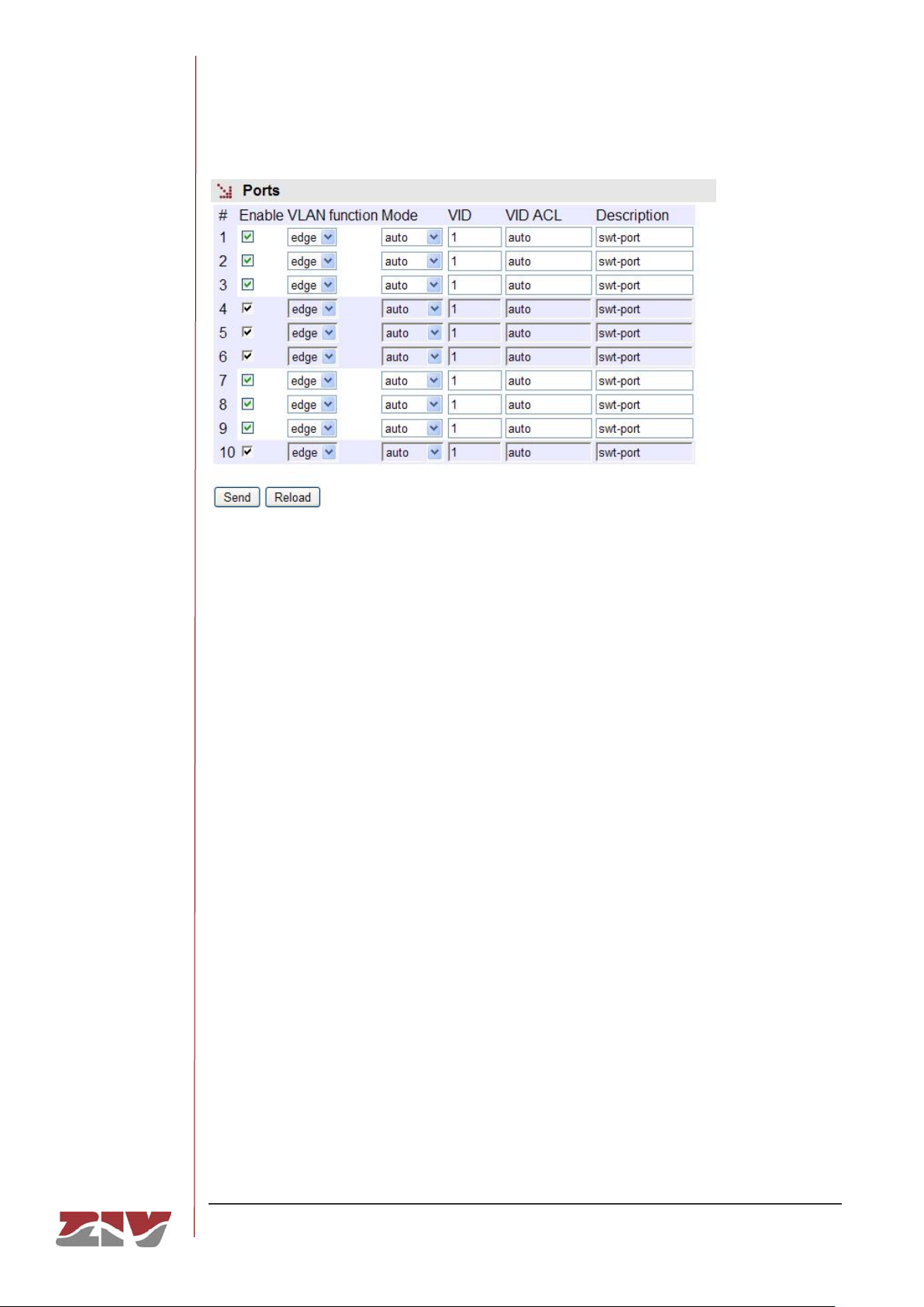
FIGURE 17 Ports submenu in the LAN menu
The configuration parameters are:
• #. This lists the ports present in the equipment. In the case of the 10/100BaseTx
interfaces the numbers coincide with the names of the connectors. Irrespective of
the final number, the last two ports are always the ones associated with the SFP
Gigabit Ethernet ports, and so, depending on whether any devices are present,
they may correspond to ports 7 and 8 (without BPLC) or to ports 9 and 10 (with 2
BPLCs); in the latter case, ports 7 and 8 are associated with the two BPLC
interfaces.
• Enable. This permits each port to be enabled or disabled individually, by ticking or
not ticking the respective Enable box.
• VLAN function. This specifies the 802.1q (edge or trunk) datagram format to be
used for transmission in the port.
Edge: The 802.1 frames will be transmitted with the same format as they had when
accepted by the equipment, with or without a tag.
When operating in PVLAN, Edge interfaces will always run untagged.
Trunk: All the frames will in all cases be transmitted with a tag. This is the specified
mode for connection with other switching equipment when the 802.1Q information
is required to be global in nature.
Page 40
DRA-2
DRA-2 UNIVERSAL COMMUNICATION NODE 40/158
USER GUIDE - Rev.5 (January 2018)
• Mode. This specifies the type of operation for the LAN port in terms of speed and
operation mode. The operating parameters of the PLC ports are established in the
PLC submenu.
Auto (autonegotiation): Recommended and value by default.
10fdx: 10 Mbit/s Full-duplex.
100fdx: 100 Mbit/s Full-duplex.
10hdx: 10 Mbit/s Half-duplex.
100hdx: 100 Mbit/s Half-duplex.
If an operation mode other than Auto is configured, both ends of the link must
be identically configured.
• VID. This indicates the VLAN in which the port is included. The assignation is made
from the VLAN submenu.
• VID ACL (Access control list). This parameter acts like a filter with regard to
packets accepted on the Port level, and only packets with a VLAN identifier
included in the list will be processed for transmission and reception purposes. All
the packets have a VLAN identifier, either because it was included when they were
received (tagged frames) or because it was assigned by the input port at the time of
reception, with the VID parameter being assigned to the port in the latter case. The
special value any signfies that the filter is not active.
• Description. A memotechnical descriptive field available to users.
5.3.2 VLAN
A Virtual Local Area Network (VLAN) can be defined as a series of devices connected in a
network which belong to one Local Area Network , even though they are connected in
different interconnection equipment, remote geographical zones, different floors of a
building or even different buildings. In other words a VLAN is a network with logical groups
which are physically independent.
Each VLAN is distinguished from the rest by a specific identifier, usually called a VLAN tag,
which is specified in standard IEEE 802.1q. The tag allows several VLANs to share
resources, including switching equipment such as the DRA-2, or links between switching
equipment, with the guarantee that the traffic from each VLAN will reach the correct
destination.
Page 41
DRA-2
DRA-2 UNIVERSAL COMMUNICATION NODE 41/158
USER GUIDE - Rev.5 (January 2018)
The fact that in relation to the equipment, the definition of the VLAN and assigning of the
ports to each one is done based on configuration parameters offers great flexibility, as it is
possible to alter the topology of the VLANs without having to make changes to the
infrastructure.
The exchange of packets between equipment belonging to different VLANs can only be
made on the routing level (L3). The DRA-2 has the capacity to perform this function
between the different VLANs defined in the equipment, so that the traffic between them
admits more control options.
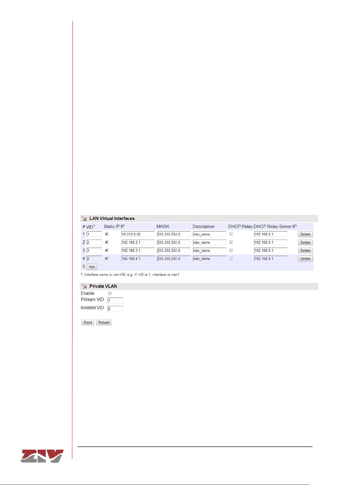
The main IP address and its mask can be obtained automatically from the DHCP client,
which is known as dynamic or NON-static configuration. Users can activate this service
through the Checkbox control with the Static IP label. When the control is marked, the
equipment uses the data provided by the user.
FIGURE 18 VLAN submenu in the LAN menu
5.3.2.1 PVLAN function
PVLAN allow the user to employ a single IP address range for a whole L2 domain while
keeping privacy among different VLANs.
PVLAN defines three types of VLAN: Primary, Isolated and Community.
There are four behaviours for the interfaces: Promiscuous, Isolated, Community and Trunk.
Page 42
DRA-2
DRA-2 UNIVERSAL COMMUNICATION NODE 42/158
USER GUIDE - Rev.5 (January 2018)
The first three are for the three types of VLAN indicated, whilst the fourth is a special extra
type, allowing using more than a single device for PVLAN domain.
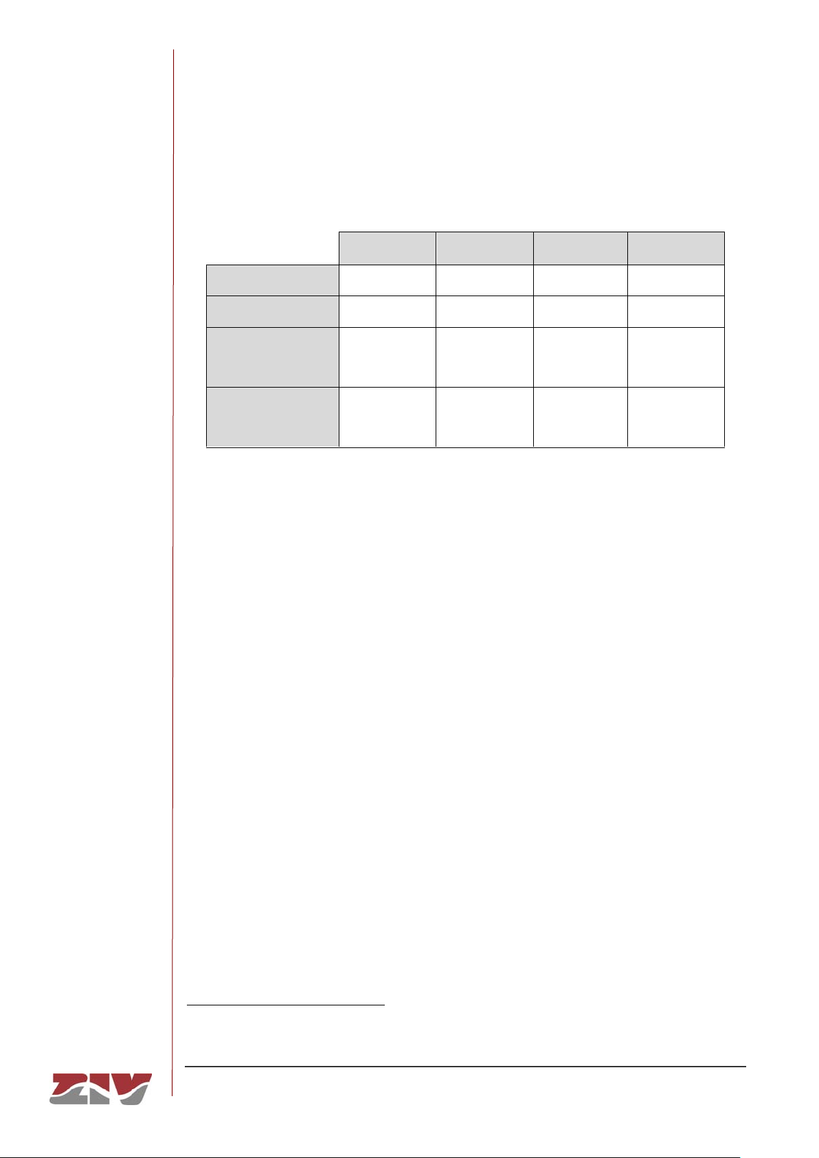
The following table shows the traffic which can flow between all these ports:
Isolated
Promiscuous
Community
Trunk
Isolated
NO
YES
NO
YES
Promiscuous
YES
YES
YES
YES
Community
NO
YES
YES for ports
sharing
community
YES
Trunk
NO
(*)
YES
YES for ports
sharing
community
YES
VLAN configuration for PVLAN behaviour is as usual, but only Primary VLAN parameters
are used in full. Only VLAN id is taken into account, so Static IP, IP, MASK, Description,
DHCP Relay and DHCP Relay Server IP parameters have no meaning.
User has special fields to identify Primary and Isolated VLANs. Any VLAN defined different
from selected ones for Primary and Isolated will be considered to be Secondary
Community.
Each Edge port behaves accordingly to which VLAN is included. Trunk ports are configured
selecting Trunk function to them.
Management is always accessible through all ports because is connected as a
Promiscuous virtual port, no matter if there are other ports running this role. Access can be
restricted using filtering rules.
*
Traffic from a Trunk port to an Isolated port will be denied if it is in the Isolated VLAN. Traffic from a Trunk port to an
Isolated port will be permitted if it is in the primary VLAN.
Page 43

DRA-2
DRA-2 UNIVERSAL COMMUNICATION NODE 43/158
USER GUIDE - Rev.5 (January 2018)
5.3.3 PLC
This submenu appears when the equipment has PLC interfaces. It allows the operating
parameters of the equipment PLC ports to be configured, whose connectors are identified
as PLC 1 and PLC 2.
The operating paradigm of the PLC interfaces is the Master-Slave type, but even so the
communication is restricted to end-to-end topologies, since one Master admits multiple
Slaves. On the other hand, the possibility of several PLC communications existing is
envisaged, either through sharing one environment or acting as interferent signals.
The mechanism for guaranteeing exclusion between several PLC communications is the
use of different codes for each one, which are also used for encrypting data, thereby
guaranteeing privacy. This identification code is called Network Management Key (NMK)
and is shared by all the equipment in one group. Each NMK is made up of a sequence of
16 bytes.
Each of the PLC interfaces must have an NMK assigned to it and in normal conditions,
different from each other. In all cases, special configurations are foreseen for the interfaces,
so that they can operate without the user having to configure them a priori. For instance, it
is possible to have a basic configuration for the equipment, even without knowing its exact
location.
These specific modes lead to the presence of configuration parameters in addition to the
NMK which are NMKs group (GNMK) and Operation mode.
Each of the 10 GNMK available includes multiple NMKs. The equipment is able to travel in
cycles through the GNMK assigned to an interface until it detects the establishing of a
successful connection (AUTO mode). It can also act like the end that accepts the
connections (ASK mode), in which case the NMK is obtained by consulting a server which
controls them, that can be enabled in the equipment itself.
The PLC interfaces in AUTO mode always try to establish connection with the last
successful NMK value.
Only one GNMK server must be enabled for all the equipment operating in the same
GNMK group.
Page 44
DRA-2
DRA-2 UNIVERSAL COMMUNICATION NODE 44/158
USER GUIDE - Rev.5 (January 2018)
A static configuration can also be used (STATIC mode) in which the NMK of each PLC
interface is established directly, and the user is then responsible for the correct
configuration thereof in all the equipment that is to be interconnected. In the latter case, the
Station Role parameter is useful.
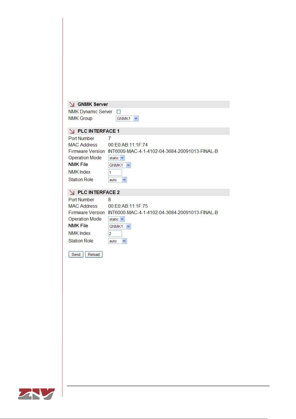
FIGURE 19 PLC submenu in the LAN menu
The configuration parameters are:
• NMK Dynamic Server. This enables the NMK codes server.
• NMK Group. This identifies the NMK group with which the interface operates, by
selecting it from the drop down menu.
Page 45

DRA-2
DRA-2 UNIVERSAL COMMUNICATION NODE 45/158
USER GUIDE - Rev.5 (January 2018)
• Operation Mode. This establishes the manner in which the equipment will obtain
the NMK for the interface.
AUTO: The equipment does not know the NMK assigned to the link to which it is
connected, and therefore executes automatic connection tests with each of the
NMK included in the configured GNMK. In this way, the role of the PLC interface is
always Station (slave).
ASK: The interface uses a specific NMK obtained by querying the GNMK Server.
In this way, the role of the PLC interface is always CCo (master).
STATIC: The NMK is use is the one indicated by the user in the selection chart.
• NMK Index. Selects an NMK in the assigned group. An index is used instead of the
code, which firstly prevents errors in entering it and secondly, ensures privacy.
• Station Role. This establishes the behaviour of the interface in terms of the
Master-Slave paradigm. The values admitted are: Auto, Station (slave) and CCo
(master). This only makes sense when the Operation Mode is STATIC.
In Auto mode the CCo (master) selection is made automatically between all the
equipment sharing one NMK, including resolution, in the event that the selected
equipment ceases to be operative.
When establishing the roles it is ESSENTIAL to guarantee that ONE equipment
exists configured with the static CCo role (master). In the event that all the
equipment is configured in static with the Station role (slave) and none is
configured as Auto or CCo (master), the PLC environment will not be available.
Equipment with roles in dynamic and static mode may coexist, provided the
above condition is fulfilled.
Page 46

DRA-2
DRA-2 UNIVERSAL COMMUNICATION NODE 46/158
USER GUIDE - Rev.5 (January 2018)
5.4 WAN CONFIGURATION
This menu appears when the equipment has WAN (GPRS/UMTS) or cable modem
interfaces.
For the WAN interface, it contains two submenus: Cell0 and Tunnel. For the cable modem
interface, it contains two submenus: Tunnel and CM.
Their functionalities are described below.
5.4.1 Cell0 configuration
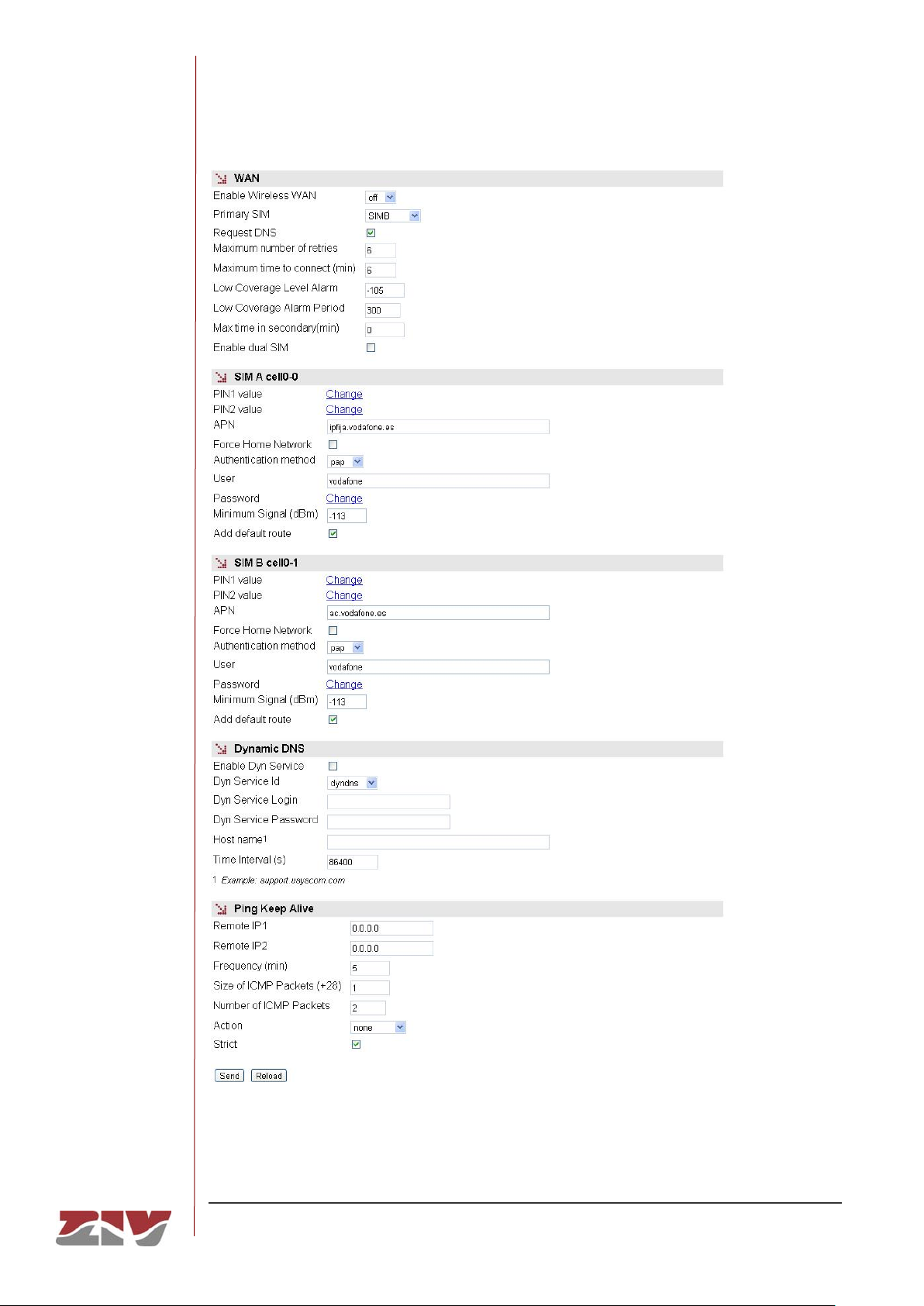
This submenu is used to configure the wireless interface data. The submenu has four
different sections, which are described below.
WAN:
• Enable Wireless WAN. This allows the WAN interface or interfaces of the
equipment to be enabled and disabled by selecting ON and OFF respectively.
Selecting the ON option will make the equipment try a new GPRS/UMTS/HSDPA
session, in accordance with the subscriber data (PIN, APN, Authentication method,
user, password). In the case of dual SIM functionality, the subscriber data will be
those corresponding to the primary SIM.
Selecting the VRRP option determines the conditioning of the behaviour of the
interface to VRRP operation, and is therefore enabled once the equipment to which
it belongs is changed to the master router.
The OFF option disables the WAN interface, and is the default option.
Consequently, you should enable this option if you want the GPRS/UMTS
service, after FIRST configuring the necessary parameters for establishing the
operator session.
• Primary SIM. In the case of dual SIM functionality, this permits users to determine
which of the two available SIMs will act as the primary one: SIMA or SIMB. In this
operating mode the SIM that is not selected is therefore the secondary or back-up
SIM. It is also possible to establish an operating mode with alternation of the SIMs
(alternated) each time the equipment is started up, as well as an operating mode
for random selection of the primary SIM each time the equipment is started up
(random).
Page 47
DRA-2
DRA-2 UNIVERSAL COMMUNICATION NODE 47/158
USER GUIDE - Rev.5 (January 2018)
FIGURE 20 Cell0 submenu in the WAN menu
Page 48

DRA-2
DRA-2 UNIVERSAL COMMUNICATION NODE 48/158
USER GUIDE - Rev.5 (January 2018)
• Request DNS. Tick this box and the equipment will request the addresses for DNS
servers if connected to the GPRS/UMTS service.
• Maximum number of retries. This gives the number of retries (3 to 10) that can be
made to try and establish the operator session. If the number of retries is used up,
the equipment will be rebooted.
In the case of dual SIM functionality, the number of retries is for each of the SIMs.
In this way, once the number of retries with the primary SIM has been used up, the
equipment will try to establish connection using the secondary SIM. If it is not
possible to connect with the secondary SIM, once the number of retries has been
used up, or if the secondary SIM is disabled, the equipment will be rebooted.
It must be taken into account that the Maximum time to connect counter starts
operation at the same time that the Maximum number of retries counter. In this
way, the equipment will be rebooted when one of the two counters reaches at zero,
that is to say, when it is not possible to connect once the number of retries of both
SIMs has been used up or once the time configured in the Maximum time to
connect counter has been used up.
It is therefore advisable to give a higher value in the Maximum time to connect
than in the Maximum number of retries.
• Maximum time to connect (minutes). This specifies the time in minutes (3 to 20)
for the equipment to wait in order to obtain the WAN IP address from the operator.
In the case of dual SIM functionality, it must be taken into account that the
Maximum time to connect counter starts operation at the same time that the
Maximum number of retries counter. In this way, the equipment will be rebooted
when one of the two counters reaches at zero, that is to say, when it is not possible
to connect once the number of retries of both SIMs has been used up (see
Maximum number of retries counter) or once the time configured in the Maximum
time to connect counter has been used up.
It is therefore advisable to give a higher value in the Maximum time to connect
than in the Maximum number of retries.
• Low Coverage Level Alarm. It specifies the coverage level under which the low
coverage level alarm should be activated.
• Low Coverage Alarm Period. It specifies the time the coverage level should
remain below the level indicated in the previous paragraph before the low coverage
alarm is activated.
Page 49

DRA-2
DRA-2 UNIVERSAL COMMUNICATION NODE 49/158
USER GUIDE - Rev.5 (January 2018)
• Max time in secondary (minutes). This parameter is associated with the dual
SIM functionality. It allows the time during which the equipment is connected to the
secondary SIM to be limited. After that time, the equipment will again try to connect
to the primary SIM. The maximum time permitted is 1440 minutes.
• Quality Sample Period (sec). This parameter defines the period of time that the
equipment uses for sampling the received signal measure, RSSI when operating
on a 2G network or RSCP and EC/n0 when the network is 3G.
• Quality Evaluation Period (sec). The user defines the period of time and thus,
indirectly, the number of samples of the received signal measure to determine
compliance with minimum quality. The signal value is individualized for each
possible operator and network type, see Min Signal GPRS and Min Signal UMTS.
The criteria for determining if the level is correct or not is that all samples of the
current evaluation period not meet the minimum set.
• Quality EC/n0 Evaluation Period (sec). This parameter is equivalent to the
above, but the measure that is evaluated is EC/n0, which only applies in 3G
networks. The threshold value is set for each operator with Max EC/n0 UMTS
parameter. The criteria for determining if the level is correct or not is that all
samples of the current evaluation period exceed the maximum set.
• Enable dual SIM. This box must be ticket to determine whether the equipment will
use the secondary SIM or not. It enables the options: SIMB, alternated and
random.
SIM A cell0-0 and SIM B cell0-1:
• PIN 1 and PIN 2 values. These are the safety codes associated with the SIM card.
Normally, PIN1 is sufficient to access the general services provided by the
operator. Check that the code entered is correct. Entering a wrong code will block
the SIM card.
Once the PIN 1 and PIN 2 values are introduced from the Change option,
execute the send command of said option, and then, if you want the values to be
applied and saved in the equipment, DO NOT forget to execute the apply and
save commands from the main menu tree.
Page 50

DRA-2
DRA-2 UNIVERSAL COMMUNICATION NODE 50/158
USER GUIDE - Rev.5 (January 2018)
• Preferred network. Only for the UMTS interface. This allows the equipment
behaviour to be specified in the case of a failure in UMTS/HSDPA coverage. When
UMTS is selected, the equipment will always try to connect to a UMTS/HSDPA
network. This option therefore involves the disconnection of the equipment, due to
the lack of UMTS/HSDPA reception. If UMTS/GPRS is selected, the equipment will
try to connect to a UMTS/HSDPA network, but if there is no UMTS/HSDPA
coverage it will connect to a GPRS network. With this option, the equipment will
permanently monitor the UMTS/HSDPA network coverage, and as soon as the
UMTS network becomes available again, it will switch from a GPRS network to a
UMTS/HSDPA network.
• APN. This establishes the identity of the operator access point.
• Force Home Network. On ticking this box connection with the operator of the local
network associated to the SIM card is forced (home network). If this option is
selected, the equipment will not connect to any operator other than the one
specified.
• Authentication method. The authentication method to be used when establishing
the PPP session must be selected. The possible values are None, PAP and CHAP.
• User Name. User name established by the operator during the authentication
process (see preceding point).
• Password. Password established by the operator to validate the user name in the
preceding point. The password is not shown for security reasons and so when it is
changed (Change option), it must be entered twice.
Once the Password is introduced from the Change option, execute the send
command of said option, and then, if you want the password to be applied and
saved in the equipment, DO NOT forget to execute the apply and save
commands from the main menu tree.
Page 51

DRA-2
DRA-2 UNIVERSAL COMMUNICATION NODE 51/158
USER GUIDE - Rev.5 (January 2018)
• Min Signal GPRS (dBm). This parameter allows a minimum coverage level to be
specified (in dBm) as a quality parameter for the GPRS (2G) connection. When the
coverage level is below this value the equipment will not try to establish the
operator session and will remain disconnected. The default values are -113 dBm
(0%, no coverage) and -51 dBm (100%, coverage).
TABLE 2 relates the AT command for coverage measurement (AT+CSQ), the
value in dBm of said coverage, and the level of coverage the equipment is
receiving, which is shown in the coverage bar on the upper strip of any of the
pages on the user interface.
• Min Signal UMTS (dBm). This parameter allows a minimum coverage level to be
specified (in dBm) as a quality parameter for the UMTS (3G) connection. When the
coverage level is below this value the equipment will not try to establish the
operator session and will remain disconnected. The default values are -113 dBm
(0%, no coverage) and -51 dBm (100%, coverage).
TABLE 2 relates the AT command for coverage measurement (AT+CSQ), the
value in dBm of said coverage, and the level of coverage the equipment is
receiving, which is shown in the coverage bar on the upper strip of any of the
pages on the user interface.
• Max EC/n0 UMTS (dB). This parameter specifies the maximum threshold of the
EC/n0 measure to be considered as acceptable.
• Min Coverage (%). The system calculates the coverage as a percentage from the
received power RSSI to 2G networks, or a combination of the received power
(RSCP) and the measured EC/n0, in the case of 3G networks. This parameter sets
the minimum threshold required to be evaluated.
• Quality criteria. The equipment samples several quality data depending on the
network technology in use. This parameter configures what action or combination
shall be evaluated in each of the periods. The options are:
o Signal: The system will analyze well RSSI (2G) or RSCP (3G) as the only
measure of quality.
o Coverage: The system shall refer the measure Min. Coverage with the
corresponding configured value to evaluate the compliance of the required
level.
Page 52

DRA-2
DRA-2 UNIVERSAL COMMUNICATION NODE 52/158
USER GUIDE - Rev.5 (January 2018)
o Signal_and_ecn0: The system will monitor both RSCP and EC/n0 and, for
the quality criteria to be satisfied, both measures must meet the
corresponding thresholds simultaneously and for the entire evaluation
period.
o Signal_or_ecn0: The system will monitor both RSCP and EC/n0 and
quality criteria are satisfied if one of the two measures meets the
corresponding threshold for the entire evaluation period.
o ecn0: The system will analyze EC/n0 as the only measure of quality.
Applicable only operating on 3G networks.
If the network in use is 2G, the Signal_and_ecn0, Signal_or_ecn0 and ecn0
criteria are interpreted as Signal. This establishes the criteria for 3G networks, and
allows the equipment to be operative although the actual network be 2G,
temporarily or permanently.
• Add default route. This parameter allows you to tell the equipment that you want
to use a cellular connection, once it is established, as the default route to the
equipment, as regards the routing functions.
The default gateway assigned by the operator will be used when the option is
enabled. If there is a default route established by the user in the Default Static
Routes block of the Routing menu, the latter is preferable, and the option of the
cellular interface would not have an effect.
Page 53

DRA-2
DRA-2 UNIVERSAL COMMUNICATION NODE 53/158
USER GUIDE - Rev.5 (January 2018)
TABLE 2 AT command for coverage measurement (AT+CSQ)
AT+CSQ
Coverage(GPRS)
Coverage (3G)
Received power
Number of bars on
screen
0
0%
0%
<-113 dBm
-
1
0%
0%
-111 dBm
- 2 1%
1%
-109 dBm
- 3 1%
3%
-107 dBm
-
4
2%
4%
-105 dBm
-
5
2%
6%
-103 dBm
- 6 3%
7%
-101 dBm
- 7 3%
8%
-99 dBm
- 8 4%
11%
-97 dBm
- 9 5%
14%
-95 dBm
-
10
6%
15%
-93 dBm
1
11
11%
21%
-91 dBm
2
12
17%
29%
-89 dBm
2
13
23%
35%
-87 dBm
3
14
29%
43%
-85 dBm
3
15
35%
49%
-83 dBm
4
16
41%
57%
-81 dBm
5
17
47%
66%
-79 dBm
5
18
53%
74%
-77 dBm
6
19
59%
85%
-75 dBm
6
20
65%
99%
-73 dBm
7
21
71%
100%
-71 dBm
8
22
77%
100%
-69 dBm
8
23
83%
100%
-67 dBm
9
24
90%
100%
-65 dBm
10
25
92%
100%
-63 dBm
10
26
94%
100%
-61 dBm
10
27
96%
100%
-59 dBm
10
28
97%
100%
-57 dBm
10
29
98%
100%
-55 dBm
10
30
99%
100%
-53 dBm
10
31
100%
100%
>-51 dBm
10
>31
0%
Unknown
-
Page 54
DRA-2
DRA-2 UNIVERSAL COMMUNICATION NODE 54/158
USER GUIDE - Rev.5 (January 2018)
Dynamic DNS:
A dynamic DNS service permits the assigning of a DNS name to equipment with a
non-permanent IP address, and the Dynamic DNS client is responsible for updating
it when it changes. In this way, from the user standpoint the equipment is always
accessible via a DNS name, and so it is not necessary to always know the IP
address assigned.
The Dynamic DNS client is entrusted with connecting to the chosen server and
updating the IP address.
To use the Dynamic DNS client, users must first register the DNS name of the
equipment with the service provider. The client can only update the IP address.
The parameters are as follows:
• Enable Dyn Service. Enables the Dynamic DNS client execution.
• Dyn Service Id. Allows you to select one of the dynamic DNS service providers
supported.
• Login and Password. Establishes the user name (login) and password (password)
for accessing the service provider.
• Host name. Name of the equipment registered with the service provider, i.e., the
name of the equipment used to identify the DRA-2 via DNS.
• Time interval (seconds). Time between accesses for the Dynamic DNS client to
update the IP address.
Ping Keep Alive:
This is a facility for checking the status of the WAN interfaces.
• Remote IP1 and Remote IP2. This establishes the IP addresses of the equipment
with which accessibility will be checked, through the sending of ICMP (ping)
packets. If the fields are at 0.0.0.0 this means the "Ping Test" function is disabled. It
is sufficient for any one of the remote equipment to respond to consider the
accessibility test valid. A field with the value 0.0.0.0 means that the option is not
enabled.
• Frequency (minutes). This allows the time passing between the sending of ICMP
(ping) packets to be specified.
Page 55

DRA-2
DRA-2 UNIVERSAL COMMUNICATION NODE 55/158
USER GUIDE - Rev.5 (January 2018)
• Timeout (secs). This allows the maximum response time to the ICMP (ping)
packets sent by the Ping Keep Alive function to be specified. It admits a range
between 5 and 60.
• Size of ICMP packets. This allows the size of the ICMP packet to be specified.
The configuration consists of indicating the extra bytes to be added to the smallest
ICMP packet, which is, by default, 28 bytes.
• Number of ICMP packets. This allows the number of ICMP packets that are sent
in each verification to be specified.
• Evaluation Model. This establishes the model for the evaluation of the
accessibility test. The options are: single and period. The single model
establishes that, if some execution of the test fails, the behaviour of the equipment
is the one defined in the Action parameter. The period model establishes, by
means of the two following parameters, a test evaluation period and an admitted
failure percentage within it.
• Evaluation Period (min). When the Evaluation model parameter is configured as
period, this establishes a period between 1 and 6000 within which a failure of the
accessibility test can be produced. All the responses to the Ping Keep Alive
packets sent in this period make the universe of samples that will be considered to
decide about the execution of Action according to the fulfilment of the criteria
established by means of the following parameter.
• Max Lost Ratio (%). This allows the maximum admitted percentage of failure in
the Evaluation period to be specified for the results of the Ping Keep Alive
messages.
• Action. This establishes the desired behaviour of the equipment if the accessibility
test is failed. The options are: None (no action taken), Reconnect (set up a new
GPRS/UMTS session) or Reboot (reboot the equipment).
• Strict. This option allows users to inhibit the accessibility test in the presence of
traffic. If the option is not activated, the test will only be executed when the period
of time indicated in frequency without traffic has passed. When the option is
enabled, the test will be performed regardless of whether traffic is present or not.
Page 56
DRA-2
DRA-2 UNIVERSAL COMMUNICATION NODE 56/158
USER GUIDE - Rev.5 (January 2018)
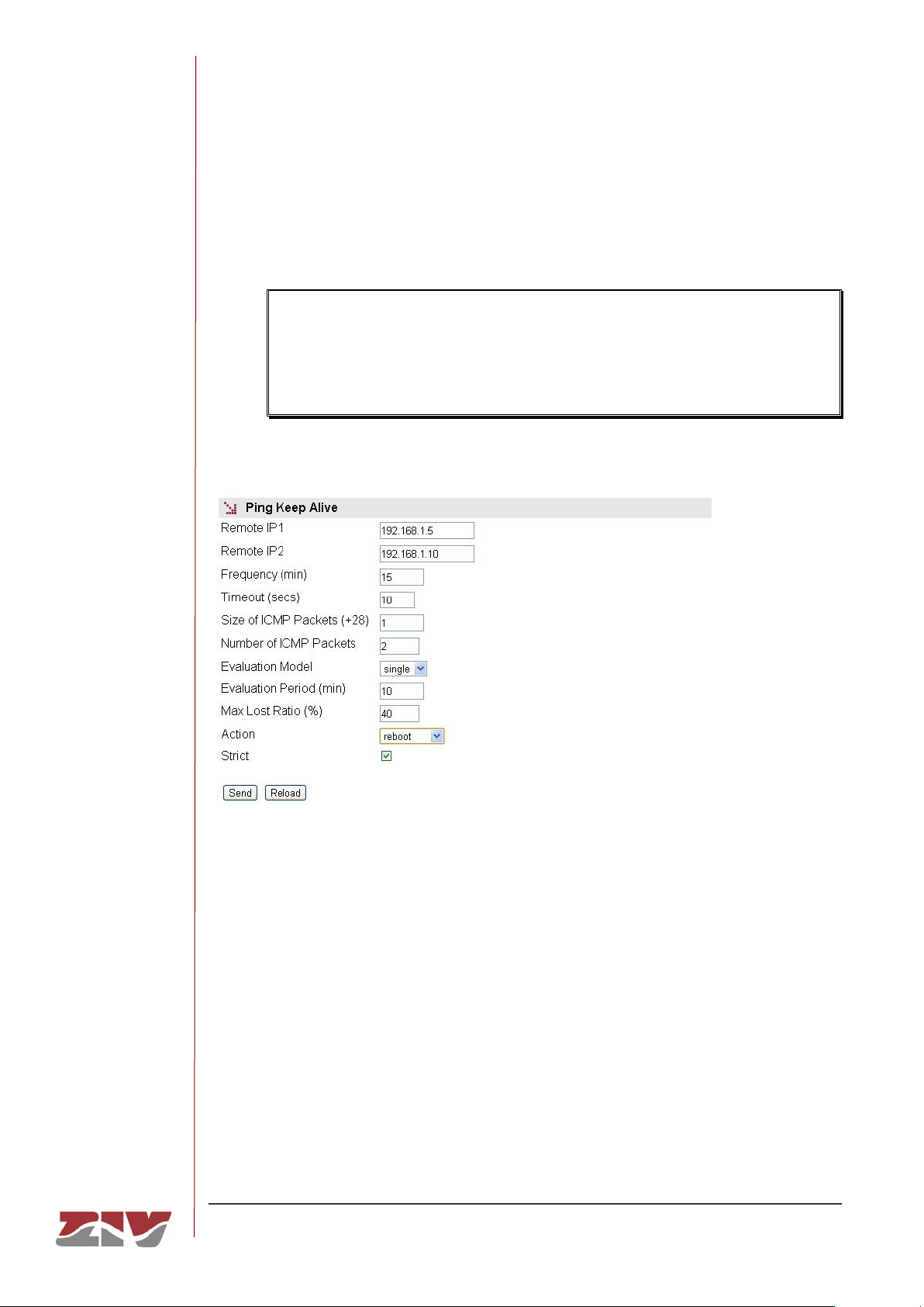
In the figure given as an example in the Ping Keep Alive configuration, connectivity
of the IP addresses 192.168.1.5 and 192.168.1.10 is verified every 15 minutes by
sending 2 ICMP packets of 29 bytes (28+1). In case of failure, the behaviour is
Single and, in this case, if there is no response to the "Ping Test", the equipment
will be rebooted.
To prevent "Ping Test" failures occurring due to the simultaneous reception of
traffic, the equipment will check the activity through the WAN interface for 30
seconds prior to executing the "Ping Test". If the reception of traffic is detected,
the "Ping Test" function will not be executed.
FIGURE 21 Example of the Ping Keep Alive configuration
Page 57
DRA-2
DRA-2 UNIVERSAL COMMUNICATION NODE 57/158
USER GUIDE - Rev.5 (January 2018)
5.4.2 Tunnel configuration
A tunnel can be defined as a virtual connection which emulates an end-to-end connection
between two nodes connected through a complex network, which may be public like
Internet or private.
To configure a tunnel, it is necessary to define the start and end points of the tunnel and the
traffic to be sent through it.
There are two types of unsafe (unencrypted) tunnels: IPIP and GRE. The difference
between them is that IPIP tunnels can only encapsulate IPv4unicast traffic, whereas GRE
tunnels admit multicast traffic.
To guarantee privacy and safety, the data circulating on the tunnel can be encrypted
through the IPSec cipher protocol. It can be configured through the VPN menu.
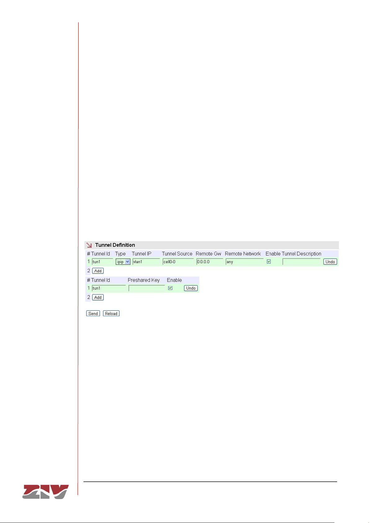
FIGURE 22 Tunnel submenu in the WAN menu
The configuration parameters are:
• Tunnel ID. This establishes the name of the virtual tunnel-like device.
• Type. This establishes the desired tunnel type; GRE or IPIP.
• Tunnel IP. This establishes the IP address associated with the virtual tunnel
device, whose identity is the value of the Tunnel ID parameter. The address must
be the host address, but it admits the inclusion of the associated net mask and also
its configuration in an indirect form, through the equipment device identifier, in
which case the IP address configured in this interface is assigned with a host mask.
Page 58

DRA-2
DRA-2 UNIVERSAL COMMUNICATION NODE 58/158
USER GUIDE - Rev.5 (January 2018)
• Tunnel Source. This establishes the local interface through which the tunnel traffic
will be routed. In the case of WAN (GPRS/UMTS) interfaces, it may be cell0-0
(identifies SIM A) or cell0-1 (identifies SIM B). Otherwise, it will be a virtual network
identifier from one of the VLANs in the equipment.
• Remote GW. This establishes the IP address of the equipment at the other end of
the tunnel, that is to say, the terminator.
• Remote network. The remote subnetwork connected to the point at the end of the
tunnel (Remote GW) whose traffic passes through the tunnel. If any is selected, all
traffic not accessible locally or based on specific rules will be sent through the
tunnel.
• Enable. This permits a tunnel to be enabled or disabled, by ticking or not ticking
the respective Enable box.
• Tunnel description. A descriptive field permitting the indication of data about the
tunnel, for example, its usefulness.
• Preshared key. A key that is exchanged between the equipment at both ends of
the tunnel, for the purpose of establishing it. It must be configured in both
terminators (Tunnel IP and Remote GW). For it to be effective, the associated
Enable box must be ticked.
Example:
An example is given below which allows the different parameters referred to above to be
identified, with specific values. The GRE tunnel is established between Routers A and B,
connected through an IPv4 network; the connection could well be the Internet.
Routers A and B route the traffic between the equipment belonging to Group 1 and Group 2
as if both routers were directly connected to each other, since they both have an IP address
in the same segment, 10.1.2.1 and 10.1.2.2 respectively, which are the IP addresses
assigned locally to each end of the tunnel; they do this in a transparent manner on the IPv4
network.
Page 59
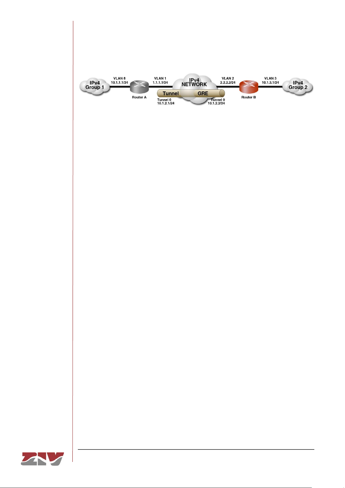
DRA-2
DRA-2 UNIVERSAL COMMUNICATION NODE 59/158
USER GUIDE - Rev.5 (January 2018)
FIGURE 23 Example of a tunnel configuration
In router A, the configuration would be:
• Tunnel ID. Tunnel0.
• Type. GRE
• Tunnel IP. 10.1.2.1/24 (IP address of the virtual Tunnel0 device).
• Tunnel Source. vlan1 (Local interface in which the local address 1.1.1.1/24 is
configured).
• Remote GW. 2.2.2.2/24 (tunnel terminator address).
• Remote network. 10.1.3.0/24 (IP network located at the remote end of the tunnel).
In router B, the configuration would be:
• Tunnel ID. Tunnel0.
• Type. GRE
• Tunnel IP. 10.1.2.2/24 (IP address of the virtual Tunnel0 device).
• Tunnel Source. Vlan2 (Local interface in which the local address 2.2.2.2/24 is
configured).
• Remote GW. 1.1.1.1/24 (tunnel terminator address).
• Remote network. 10.1.1.0/24 (IP network located at the remote end of the tunnel).
Page 60
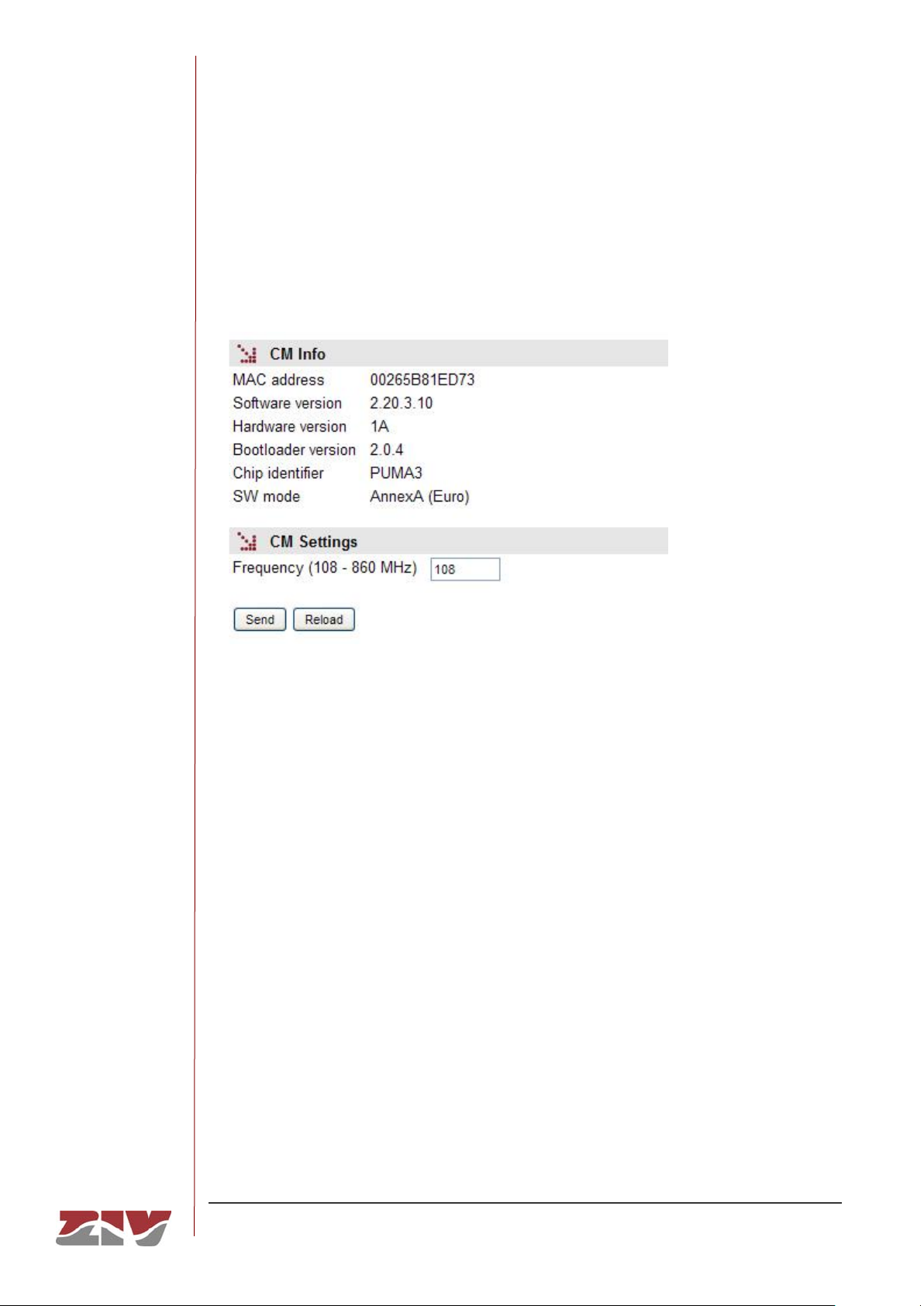
DRA-2
DRA-2 UNIVERSAL COMMUNICATION NODE 60/158
USER GUIDE - Rev.5 (January 2018)
5.4.3 CM configuration
This submenu is used to configure the cable modem data. The submenu has two different
sections, which are described below.
FIGURE 24 CM submenu in the WAN menu
CM info:
The CM system details are configured.
• MAC address. HFC device MAC address.
• Software version. Software version being executed by the CM.
• Hardware version. CM hardware version.
• Bootloader version. CM boot code version.
• Chip identifier. CM device identifier.
• SW mode. Operation mode identifier: EuroDOCSIS o DOCSIS.
CM Settings:
• Frequency (108-860 MHz). It permits the initial frequency that will be synchronized
with the main HFC to be established. If there is no synchronization, the CM scans
the frequency range associated with the operation mode (SW mode).
Page 61

DRA-2
DRA-2 UNIVERSAL COMMUNICATION NODE 61/158
USER GUIDE - Rev.5 (January 2018)
5.5 QoS CONFIGURATION
The Quality of Service (QoS) permits the classification of the packets in data queues and
the service policy for them.
The equipment provides QoS at level 2 (switching) and level 3 (routing). The QoS facilities
of both levels are independent from each other, but the fact that they share the possibility of
using the DSCP parameter enables coherent behaviours to be obtained at both levels.
5.5.1 QoS Layer 2
Level 2 QoS is performed on switched traffic, adjusted to the processing of parameters and
behaviour of IEEE 802.1p, with three internal priority levels. This priority is taken into
account for establishing the processing and transmission order in each switch output
interface.
Two potential service policies are admitted in processing the queues for each priority:
Priority or Weight Fair Scheduling (WFQ). The Priority policy only serves a queue with a
lower priority when the higher priority queues are empty. The WFQ policy guarantees a
weighted service for all the priority, but preeminently to queues with a high priority.
The service policy is unique for level 2 service. The parameters are the VLAN and priority
802.1p (included in the tag or assigned depending on the input port) or the DSCP field of
level 3.
The priority supported by standard 802.1p admits values of between 0 and 7. The untagged
frames received are given a priority within that range, depending on the interface through
which they were received, pursuant to the section entitled QoS Layer 2 (ports). Tagged
frames may include both the VLAN identifier as the priority (tagged) or only the priority
(priority tagged, VLAN = 0). If the VLAN identifier is included, they are processed in
accordance with the rules of the section entitled QoS Layer 2 (VLANs). If, on the contrary,
they only include the priority, they are processed in accordance with the section entitled
QoS Layer 2 (ports).
In all cases, with the except for assigning by DSCP which is done directly on the internal
queues, the priority assigned is used for the final classification, as indicated in the section
VLAN Priority Mapping.
Page 62
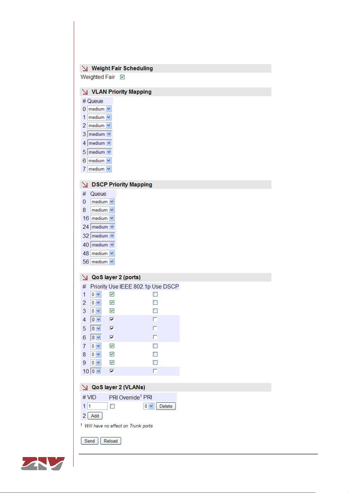
DRA-2
DRA-2 UNIVERSAL COMMUNICATION NODE 62/158
USER GUIDE - Rev.5 (January 2018)
FIGURE 25 Layer 2 submenu in the QoS menu
Page 63

DRA-2
DRA-2 UNIVERSAL COMMUNICATION NODE 63/158
USER GUIDE - Rev.5 (January 2018)
The sections and their configuration parameters are as follows:
Weight Fair Scheduling:
• Weighted Fair. This establishes the level 2 priority service policy. When the NO
option is enabled, the policy is Priority. When the Yes option is enabled, the policy
is WFQ.
VLAN Priority Mapping:
• #. This identifies the value of the priority associated with frame 802.1 (it covers the
whole range of values permitted by the standard).
• Queue. This establishes the queue priority in which the traffic coinciding with the
priority value indicated by the # field will be inserted. The values permitted identify
the three internal priorities: High, Medium or Low.
DSCP Priority Mapping:
• #. This identifies the value of the DSCP field being processed.
• Queue. This establishes the queue priority in which the traffic coinciding with the
DSCP value indicated by the # field will be inserted. The values permitted identify
the three internal priorities: High, Medium or Low.
QoS layer 2 (ports):
• #. The physical interface identifier.
• Priority. Value of the priority assigned to frame 802.1 received through the
interface indicated by #. This priority is assigned when the frames received do not
include an 802.1p tag. The assigning of internal priorities is done based on the
values established in the section entitled VLAN Priority Mapping.
• Use IEEE 802.1p. The enabled option indicates that the priority field present in the
frames must be used when they include tag 802.1p. The assigning of internal
priorities is done based on the values established in the section entitled VLAN
Priority Mapping.
Page 64

DRA-2
DRA-2 UNIVERSAL COMMUNICATION NODE 64/158
USER GUIDE - Rev.5 (January 2018)
• Use DSCP. The enabled option indicates that the DSCP field of the frames
received must be processed, to assign the internal frame priority of the frame,
based on the values established in DSCP Priority Mapping.
The options Use IEEE 802.1p and Use DSCP may be activated simultaneously.
The hierarchy for the final priority assigned to the frame is the following: DSCP,
IEEE 802.1p and Priority (user); so that:
- The priority established by the user will be associated to an untagged frame.
- The priority present in the frame will be maintained in a tagged frame, provided
the DSCP field is not present (traffic or IP) or does not coincide with any of the
specified values.
QoS layer 2 (VLANs):
This section includes a table that allows groups of parameters to be added and
eliminated.
• #. Indicates the position in the table.
• VID. VLAN identifier value included in tag 802.1.
• PRI Override. This establishes whether the priority of the VLAN frames which
coincides with that of the VID field must be overridden (enabled option) or whether
the priority received must be maintained (disabled option).
• PRI. This establishes the priority assigned to the VLAN frames coinciding with the
VID field if the PRI Override option is enabled.
5.5.2 QoS Layer 3
Level 3 QoS classification rules consider as eligible parameters: the origin IP address, the
destination IP address (both admit networks using the mask for this), type of service and
the specific level 3 DSCP field. The result is the assignment of each of the packets to one
of the three possible queues that can exist in each interface: high, medium and low.
It has also service policies, but they can be configured for each interface on level 3. The
available policies are: FIFO, Priority, HTB and HTB-Shared.
Page 65
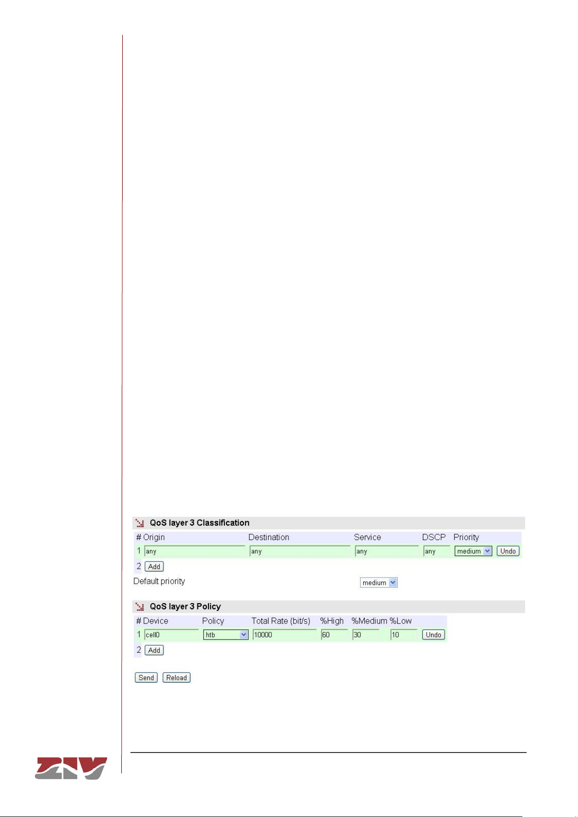
DRA-2
DRA-2 UNIVERSAL COMMUNICATION NODE 65/158
USER GUIDE - Rev.5 (January 2018)
The default service policy is Priority. However, as in the absence of specific rules, in
practice, all traffic is classified with the same priority. The policy under these conditions is
FIFO.
In the event of classification rules existing, the Priority policy is automatically put into
operation.
As an alternative, there is the option of specifying the HTB or HTB-Shared policy
individually for each device. HTB stands for Hierarchical Token Bucket. The service policy
allows the weighted share of the bandwidth to the data flows generated by the classification
rules, which are always three (high, medium and low).
The weighting is configured with a percentage of the available bandwidth, which in turn, is a
parameter that must be specified by the user.
The difference between HTB and HTB-Shared is that in the first case, the bandwidth is
assigned strictly in accordance with the weighted values; even if one of the classes does
not use the assigned bandwidth the other classes will never exceed the configured
percentage value, that is to say, the percentage values are in all cases maximum limits that
will never be exceeded. On the contrary, the HTB-Shared policy allows the use of a
bandwidth not occupied by other classes if any of them exceeds the limit. In these case,
the percentage values act like minimum guaranteed limits in the case of full occupation,
while also admitting traffic peaks that exceed the guaranteed value when there is no full
occupation.
FIGURE 26 Layer 3 submenu in the QoS menu
Page 66

DRA-2
DRA-2 UNIVERSAL COMMUNICATION NODE 66/158
USER GUIDE - Rev.5 (January 2018)
The sections and their configuration parameters are as follows:
QoS Layer 3 Classification:
This section creates the classification rules, based on a tubular structure. The
parameters for each rule are:
• Origin. This establishes the source IP address of the packet associated with this
classification rule. The field requires the values to be entered in the IP address
format. Example: 192.168.0.0/255.255.255.0 or 192.168.0.0/24. The value any is a
valid value, and means that the source IP address will not be analysed.
• Destination. This field is the same as the previous one, but analysing the
destination IP address.
• Service. The condition is established based on a specific service (tcp/udp/icmp),
and after the service the port number (1÷65535) must be indicated, separated with
two points. The default value is any and means that the service will not be
analysed as part of the condition.
• DSCP. The field analysed is the information on the class of level 3 service, DSCP
(Differentiated Services Code Point). The user directly configures the value for
fulfilling the condition. It is a numerical value between 0 and 31 (strict value of the
full DSCP field). It admits the any value as a all-purpose word, to eliminate this part
of the condition.
• Priority. This establishes the priority of the packet in the case of it fulfilling all the
requirements established by the rule. The values are High, Medium and Low.
The Default priority field establishes the priority in all cases in which the packet fails
to comply with any of the rules established, or if no rules are configured. The values
are the same as the Priority field.
QoS Layer 3 Policy:
In this section the user can assign the HTB or HTB-Shared policies specifically to a
device. If this is not done, the service policy is Priority for all of them (see the
introductory section).
The configuration is also tabulated, and the parameters for each of the assignations are
the following:
• Device. Identifies the device to which the policy specified by the following
parameters will be applied.
Page 67
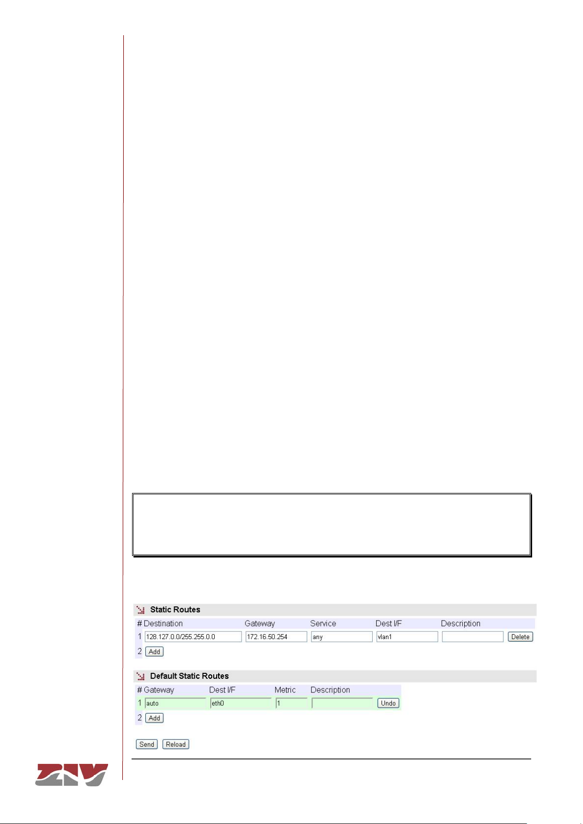
DRA-2
DRA-2 UNIVERSAL COMMUNICATION NODE 67/158
USER GUIDE - Rev.5 (January 2018)
• Policy. This establishes the service policy for the queues in each of the three
priorities. The values are htb and htb-shared.
• Total rate. This indicates the bandwidth associated with the device. The units are
bits per second (bps).
• %High, % Medium and % Low. These three fields indicate the bandwidth
percentage to be assigned to each priority.
5.6 ROUTING CONFIGURATION
The equipment operates as a router for the IPv4 protocol. The router services are always
active. The data for the routing function may have two sources; static data of a permanent
nature established by the user and dynamic data, obtained by the equipment itself through
executing the standard routing protocols: RIP and OSPF.
5.6.1 Static routes
Through the Static routes submenu in the Routing menu, the user can provide the system
with the static and permanent data for the routing service.
Two types of data are configured in this submenu; explicit static routes in the section Static
Routes, and the address acting as a route by default in the case that the service has no
specific data for reaching a destination, in the section Default Static Routes.
If the equipment has wireless operative interfaces, the operator will not only provide the
IP address of the interface but also establish a default router associated with that
interface, which takes precedence over any configuration established by the user.
FIGURE 27 Static routes submenu in the Routing menu
Page 68

DRA-2
DRA-2 UNIVERSAL COMMUNICATION NODE 68/158
USER GUIDE - Rev.5 (January 2018)
The parameters for configuring a static route are:
• Destination. This allows the IP address to be specified, and the remote or
destination network subnet mask. The field requires the values to be entered in the
IP address format. Example: 192.168.0.0/255.255.255.0 or 192.168.0.0/24.
• Gateway. This allows the IP address of the router to which the traffic destined for
the remote network of the previous field must be sent.
• Service. This allows an additional filter to be established in the remote IP address
for determining the selection of the next jump. The condition is established based
on a specific service (tcp/udp/icmp). After the service the port number (1÷65535)
must be indicated, separated by two points. The default value is any, that is to say,
the route applies for all types of traffic (only the IP destination is taken into
account). Example: tcp:5000, which means that all the packets with tcp traffic on
port 5000 will be sent to the indicated router.
• Dest I/F (Destination interface). This allows the interface through which the
routed traffic coinciding with this route will be sent. The interfaces are identified by
the associated device, which may be real, e.g. cell0 for a WAN interface or virtual,
for the different devices associated with each VLAN that is defined, e.g. vlan1.
• Description. This permits a description of up to 15 alphanumerical characters to
be specified.
Example:
The figure shows an example of assigning a static route between two different network
segments. All the TCP packets of port 40000 can reach the network segment 172.23.0.0/24
through router 192.168.0.11.
Page 69
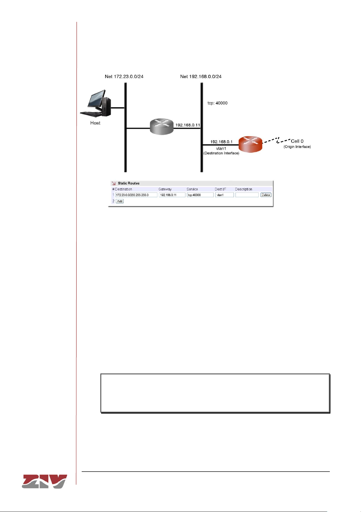
DRA-2
DRA-2 UNIVERSAL COMMUNICATION NODE 69/158
USER GUIDE - Rev.5 (January 2018)
FIGURE 28 Example of how a static route is configured
The default parameters for configuring a static route are:
• Gateway. This allows the IP address of the next router to be specified for routing
traffic whose destination does not coincide with any known route.
• Dest I/F (Destination interface). This permits the specification of the interface
through which traffic routed to the router indicated in the previous field will be sent.
The interfaces are identified by the associated device, which may be real, e.g. cell0
for a WAN interface or virtual, for the different devices associated with each VLAN
that is defined, e.g. vlan1.
• Metric. This permits a value to be established originating from among the default
different routes that could be created. A higher metric means a lower priority.
If the wireless interface is operative, this parameter must be different and higher
than 1, the value 10 being recommendable as values higher and next to 1 could
be reserved to other routes established by the operator.
• Description. This permits a description of up to 15 alphanumerical characters to
be specified.
Page 70
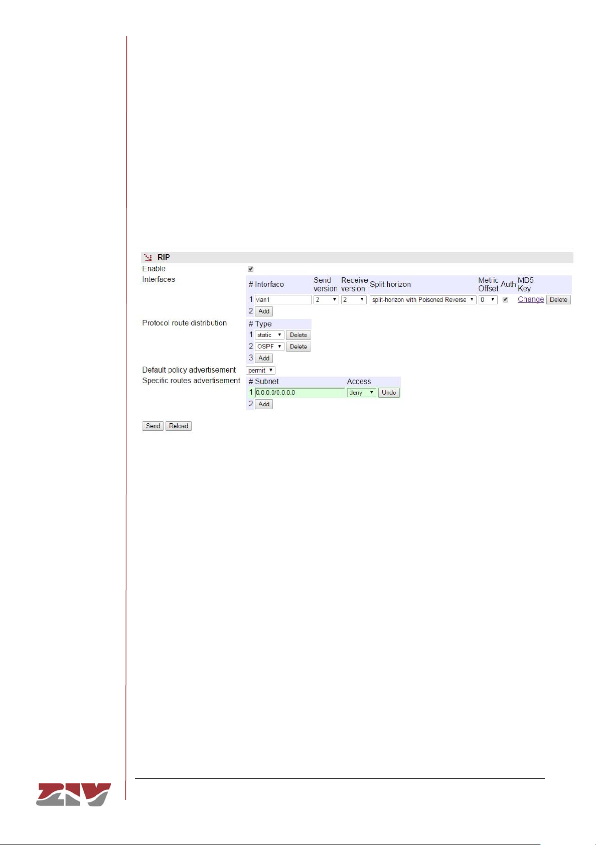
DRA-2
DRA-2 UNIVERSAL COMMUNICATION NODE 70/158
USER GUIDE - Rev.5 (January 2018)
5.6.2 RIP Protocol
The equipment has the standard RIPv1 [1] and RIPv2 [2] routing protocol.
The RIP protocol can be enabled or disabled by the user, through the Checkbox Enable
control. If the user enables the protocol, the interfaces in which it is required to be operative
must also be established.
FIGURE 29 RIP Protocol submenu in the Routing menu
The configuration parameters for each interface are:
• Interface. This identifies the real or virtual device in which the protocol execution
must be enabled.
• Send version. This establishes the protocol version to be use by the equipment to
transmit the routing data on the specified interface. The options are: none (no
information transmitted), 1 (version 1), 2 (version 2) and 1-2 (information
transmitted with both versions).
• Receive version. This establishes the protocol version accepted by the equipment
in the messages received in the specified interface. The options are: none (no RIP
message accepted), 1 (only messages with version 1 will be processed), 2 (only
messages with version 2 will be processed) and 1-2 (messages with either version
are accepted).
Page 71

DRA-2
DRA-2 UNIVERSAL COMMUNICATION NODE 71/158
USER GUIDE - Rev.5 (January 2018)
• Split-horizon: This establishes the criteria to be used in processing the routing
data, in order to prevent the “counting to infinity” problem. The options are: no splithorizon, split-horizon and split-horizon with poisoned reverse (See section 3.4.3 of
[2], bibliography reference).
• Metric offset: This field allows the user to set a weight that is added to the metric
of the routes advertised by each of the interfaces. Valid values are from 0 to 15.
Value 0 is not altering the metrics, and 15 is the maximum value that is accepted
as valid metric in RIP. Value 16 is interpreted as infinity.
• Auth: This field enables authentication for RIP messages sent on the interface
and, in turn, implies the requirement that the received messages are also
authenticated. Authentication using MD5 is always performed.
• MD5 Key: This text field sets the key that is used to calculate the MD5 hash that is
used for the authentication of the RIP packets. Its maximum length is 16
characters.
The common configuration parameters for all interfaces are:
• Protocol Route Distribution. This allows it to be indicated whether the protocol
must include not only the routing information obtained through the protocol
messages and IP data of the local interfaces, but also the routing data specified in
the static routes section or other protocols.
• Default policy advertisement and Specific routes advertisement. These two
parameters allow filtering options to be established on the routing information. The
first establishes the general filter criteria (permit or reject) and affects all the routes.
The second permits the desired exceptions to the general criteria to be indicated,
and therefore each specific input also includes the permit or reject option.
General criteria options combined with possible exceptions allow the filter to behave in two
ways:
• Send all with exceptions. The general permit criteria option, which is the default
value, with the exclusions established in the respective section, which in this case,
would have the reject option enabled.
• Only exceptions sent. The general reject criteria option, with the exceptions
established in the respective section, which in this case would have the permit
option enabled.
Page 72
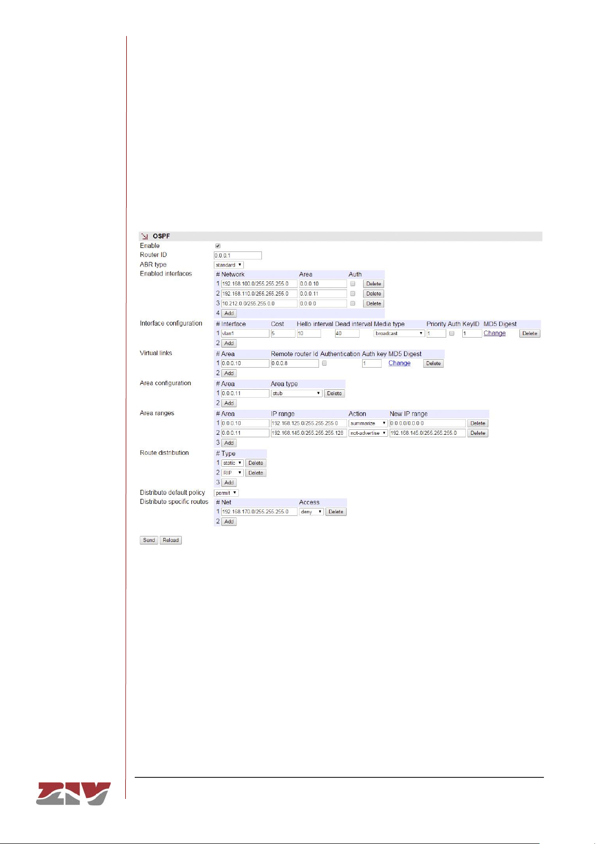
DRA-2
DRA-2 UNIVERSAL COMMUNICATION NODE 72/158
USER GUIDE - Rev.5 (January 2018)
5.6.3 OSPF Protocol
The equipment has the standard OSPFv2 routing protocol.
The OSPF protocol can be enabled or disabled by the user, through the Checkbox Enable
control.
FIGURE 30 OPSF Protocol submenu in the Routing menu
The group of parameters necessary to execute the protocol and the conditions thereof are
described below:
• Router ID: Identifies the equipment. Although the format coincides with that
normally used for an IP address, it is really a digit to distinguish the routers
executing the OSPF protocol from each other. Normally, it coincides with one of the
IP addressed assigned to the router.
Page 73

DRA-2
DRA-2 UNIVERSAL COMMUNICATION NODE 73/158
USER GUIDE - Rev.5 (January 2018)
• ABR Type: This field allows to change the behaviour of the router. In default
conditions, it is according to the standard, but it admits as alternative options cisco
and ibm values, which are equivalent. When the value is different from standard,
the router can consider the messages received from other ABR through areas
other than the backbone, when in normal conditions would not. Behaviour change
is consistent with the implementation described in Cisco routers and IBM. It must
be taken into account that areas with full adjacency through virtual links are
considered with full capacity for transit. In this way, they can be used to route the
traffic of the backbone, and this configuration do not affect them.
• Enabled interfaces: This has three values, the first being an IP address or range
of IP addresses, which means that the interface or interfaces whose IP addresses
are included in the referred range will execute the OSPF protocol, and their area
will be that indicated by the Area parameter (second parameter); despite the fact
that it is usually represented as an IP address, it is the element identifying the Area
to which the interfaces included by the first value are connected. All the routers with
interfaces operating in the same area share that identification element. The area
with the identifier 0.0.0.0 is valid and acts like a backbone, since all the areas must
be connected to it. The third parameter determines whether messages for the
defined area should provide and require authentication, using MD5 for it. The value
for the calculation of the hash must be configured in the following section of
interface configuration given that, with different interfaces of the same area, it is
possible to use different keys.
• Interface configuration: The interfaces on which the protocol runs allow the
modification of various parameters associated with them. The parameters are:
o Interface: Identification of the interface to be configured.
o Cost: Cost associated with the link for the interface. The cost is the value
used in the field associated with the metric of the router-LSA messages
and it will be used to calculate the SPF algorithm (Shortest Path First). The
default value is 5.
o Hello interval: Sets the value, in seconds, of the timer that controls the
transmission of the Hello messages. The default value is 10 s.
o Dead interval: Sets the value, in seconds, of the timer that monitors the
inactivity and waiting processes of the remote routers. The default value is
40 s.
Page 74

DRA-2
DRA-2 UNIVERSAL COMMUNICATION NODE 74/158
USER GUIDE - Rev.5 (January 2018)
o Media type: Identifies the media type associated with the interface. Valid
values are: broadcast, non-broadcast, point-to-multipoint and
point-to-point.
o Priority: Identifies the media type associated with the interface. Valid
values are: broadcast, non-broadcast, point-to-multipoint and point-to-
point.
o Authentication: This parameter controls the use of the MD5
authentication, on the interface, for the protocol messages.
o KeyID: Parameter that identifies the secret key used to create the MD5
Digest (next parameter). The field is part of the protocol and should be
consistent in all routers operating in the same link. The accepted value
range is between 1 and 255.
o MD5 Digest: Key used to generate the MD5 hash that is used as
authentication. Its value is linked to the KeyID parameter. The maximum
lenght is 16 characters.
• Virtual links: It offers the possibility of creating virtual links in order that routers
that do not have interfaces in the backbone (area 0.0.0.0) can have connectivity.
The Area parameter indicates in which of the equipment access areas the virtual
connection will be created. The equipment identifier in which the virtual connection
will be carried out is configured in Remote router Id. By means of an option it is
possible to enable the use of MD5 authentication for the said connection. The Auth
Key parameter is a numeric value that must be shared by the remote end
(according to protocol standard). The last parameter, MD5 Digest, sets the
alphanumeric key to generate the MD5 hash. The maximum length is 16
characters.
• Area configuration: This parameter sets a behaviour that be alternative to the
standard, as detailed in the protocol specification. The types are stub and
stub_no_summary (also known as Not So Stuby Area or NSSA). The area identifier
must be specified in Area as well as the desired topology.
• Area ranges: This parameter sets rules for the intra-area route processing when
the routes are announced in other areas (protocol type 3 messages). The
parameters are:
Page 75

DRA-2
DRA-2 UNIVERSAL COMMUNICATION NODE 75/158
USER GUIDE - Rev.5 (January 2018)
o Area: Identifies the area in which the address range of the following
parameter must be detected.
o IP Range: Address range, by means of mask, that will involve the
execution of the configured action.
o Action: There are three options: summarize, not-advertise and substitute.
Summarize: if in the configured area there is any address included in the
established range, the IP range as address in a message of type 3 will be
announced to the rest of the areas (in practice, all the networks of the
range are agglomerated in an unique announced address).
Not-adverstise: in the same detection conditions, instead of grouping the
addresses, the router will not announce the addresses to the other areas.
Substitute: it is equivalent to summarize, but instead of the detection range,
the established route will be announced in the following field.
o New IP Range: Value to be announced if the Action is substitute and an
address exists in the Area included in the detection range of IP Range.
• Protocol Route distribution: This allows it to be indicated whether the protocol
must include not only the routing information obtained through the protocol
messages and IP data of the local interfaces, but also the routing data specified in
the static routes section or other protocols.
• Distribute default policy y Distribute specific routes: These two parameters
establish filtering options of the routing information obtained by means other than
OSPF protocol. The first establishes the general filter criteria (permit or reject) and
affects all the routes. The second permits the desired exceptions to the general
criteria to be indicated, and therefore each specific input also includes the permit or
reject option.
General criteria options combined with possible exceptions allow the filter to behave in two
ways:
• Send all with exceptions. The general permit criteria option, which is the default
value, with the exclusions established in the respective section, which in this case,
would have the reject option enabled.
• Only exceptions sent. The general reject criteria option, with the exceptions
established in the respective section, which in this case would have the permit
option enabled.
Page 76
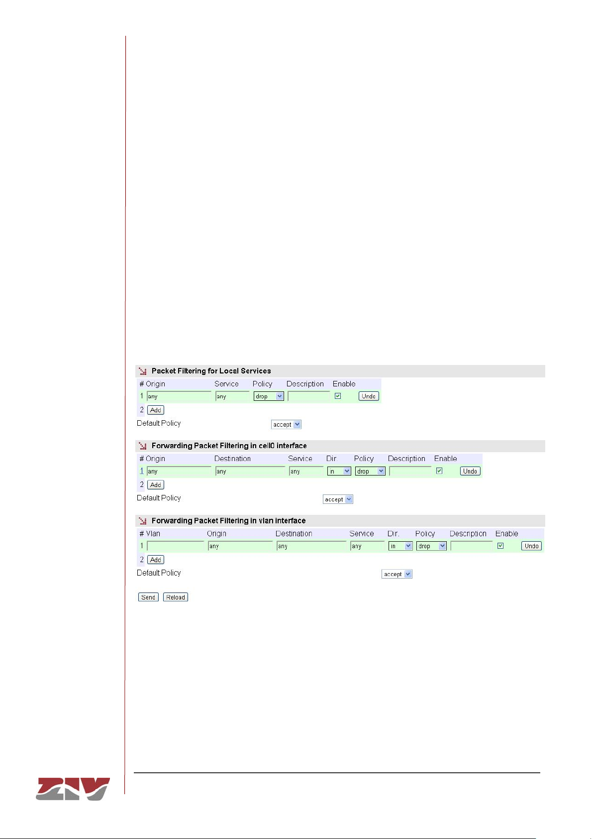
DRA-2
DRA-2 UNIVERSAL COMMUNICATION NODE 76/158
USER GUIDE - Rev.5 (January 2018)
5.7 FILTERING CONFIGURATION
The Filtering menu permits firewall functionalities, defining which traffic is allowed and
which traffic is rejected and the application of additional conditions to the traffic processed
through the routing function.
The menu parameters are divided into three quite different blocks, which are:
Filtering of packets for local services (for example: http, Telnet, etc.)
Filtering of packets through the incoming/outgoing service for WAN interfaces.
Filtering of packets through the incoming/outgoing service for virtual interfaces associated
with each VLAN that is defined.
FIGURE 31 Filtering menu
The configuration parameters in each block are:
• Origin. This allows the IP source of the traffic to be specified, i.e., from a specific
IP address or any IP address (any). The default value is any. The specification of a
particular IP address requires the values to be entered in the IP address format.
Example: Subnet (192.168.50.0/255.255.255.0 or 192.168.50.0/24) or Host
(192.168.50.5/255.255.255.255 or 192.168.50.5/32 or 192.168.50.5). Only present
in the sections in which this makes sense.
Page 77

DRA-2
DRA-2 UNIVERSAL COMMUNICATION NODE 77/158
USER GUIDE - Rev.5 (January 2018)
• Destination. This allows the IP source of the traffic to be specified, i.e., to a
specific IP address or from any IP address (any). The default value is any. The
specification of a particular IP address requires the values to be entered in the IP
address format. Example: Subnet (192.168.50.0/255.255.255.0 or
192.168.50.0/24) or Host (192.168.50.5/255.255.255.255 or 192.168.50.5/32 or
192.168.50.5).
• Service. This allows any type of traffic to be specified (any) or a specific traffic
(tcp/udp/icmp). The default value is any. If a specific traffic is indicated, the port
number can be indicated together with the service, if required (1÷65535) or a
range. Example: tcp or tcp:23 or udp:5001-5005.
• Dir. This allows the traffic way to be specified, i.e., whether it is incoming (in) or
outgoing (out).
in: incoming by Vlan In and outgoing by Vlan Out.
out: incoming by Vlan Out and outgoing by Vlan In.
• Policy. This allows the filtering policy to be specified (accept, drop or reject).
When the filtering policy is accept, only packets complying with the established
rule are accepted. When the filtering policy is drop, on the other hand, packets
complying with the established rule are dropped. The reject filtering policy also
rules out packets complying with the established rule, but unlike drop, when the
packet is ruled out, the appropriate ICMP message is sent to the source address of
the packet.
• Description. This permits a description of up to 15 alphanumerical characters to
be specified.
• Default Policy. This allows the behaviour of the equipment filtering to be
determined as regards not being included in any specific rule of the respective
section.
• Vlan In and Vlan Out. Identifiers for the virtual interfaces associated with each
VLAN that is defined.
Page 78
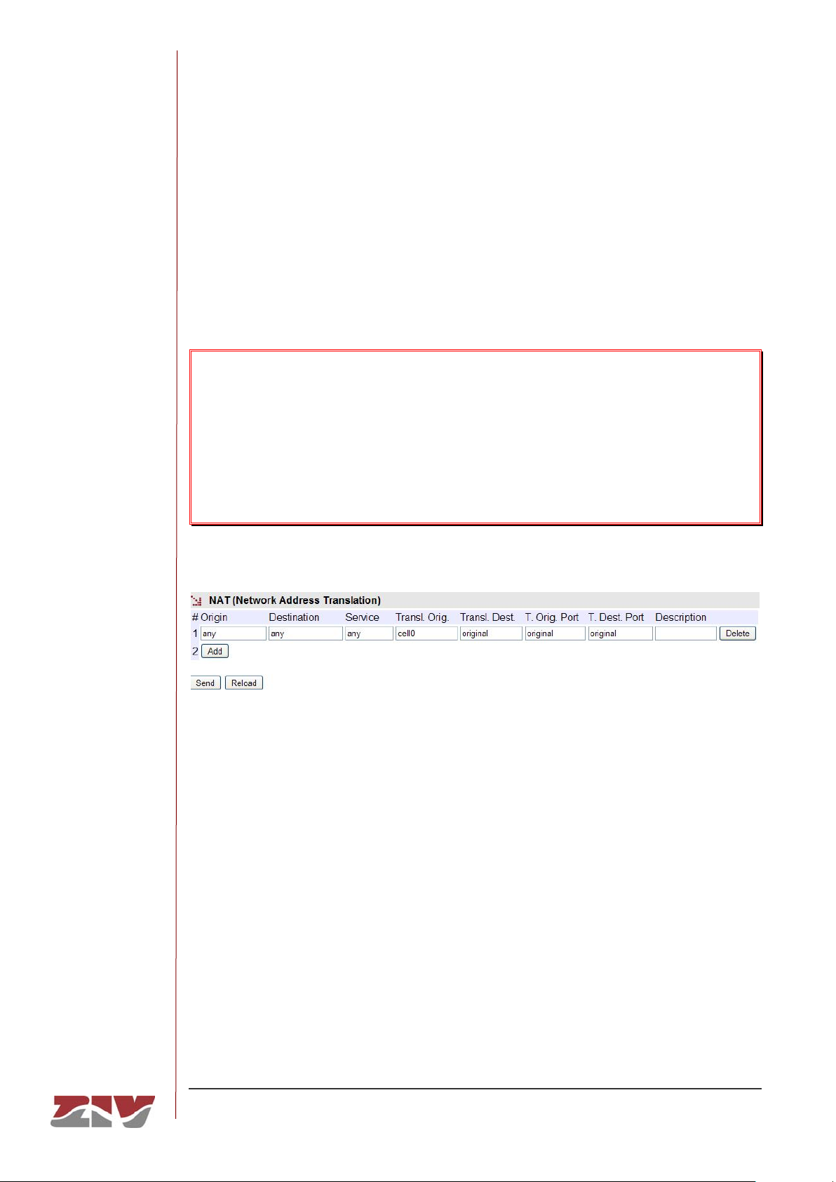
DRA-2
DRA-2 UNIVERSAL COMMUNICATION NODE 78/158
USER GUIDE - Rev.5 (January 2018)
5.8 NAT CONFIGURATION
NAT is the IP address translation service which allows users to combine the use of private
IP address without this preventing them from accessing resources with a public IP address,
or preserve the address schema in different interconnected network areas.
The NAT menu defines the rules that allow IP addresses to be selectively translated and
change the transmission service ports.
It is important to bear in mind that the NAT service has a default rule.
The correct operation of services based on its operation in analysing data which can
be changed by the NAT rules could be altered by the presence of this default rule,
since the services have a specific order of execution.
If not using NAT, this default rule must be eliminated.
FIGURE 32 NAT menu
The configuration parameters are:
• Origin. This establishes a range of IP addresses. It admits the value any, in the
case that the origin IP address is not relevant.
• Destination. This establishes a range of IP addresses. It admits the value any, in
the case that the IP destination address is not relevant.
• Service. This establishes conditions related to service, understood as the protocol
(tcp/udp/icmp) and port (1 to 65535 or a range). It admits the value any, in the
case that the service is not relevant. Example: tcp or tcp:23 or udp:5001-5005.
Page 79

DRA-2
DRA-2 UNIVERSAL COMMUNICATION NODE 79/158
USER GUIDE - Rev.5 (January 2018)
• Transl. Origin. This establishes the IP address that must replace the origin IP. An
IP address may be specified, or the respective interface identifier. In the case of not
wanting to change the original address, the value must be original.
• Transl. Dest. This establishes the IP address that must replace the destination IP.
An IP address may be specified, or the respective interface identifier. In the case of
not wanting to change the original address, the value must be original.
• T. Orig. Port. This establishes the identifier of the port that must replace the origin
port in the packet. It admits a range configuration. In the case of not wanting to
change the original port, the value must be original.
• T. Orig. Port. This establishes the identifier of the port that must replace the
destination port in the packet. It admits a range configuration. In the case of not
wanting to change the destination port, the value must be original.
• Description. This permits a description of up to 15 alphanumerical characters.
5.9 DHCP RELAY CONFIGURATION
The DRA-2 DHCP Relay Agent is a Bootstrap Protocol (BOOTP) relay agent that relays
Dynamic Host Configuration Protocol (DHCP) messages between DHCP clients and DHCP
servers on different IP networks.
DHCP Relay agent can be enabled for each VLAN configured (VLAN menu), and the single
parameter needed is IP address for DHCP Server that DHCP demands will be sent.
DHCP Relay agent can also be enabled when equipment is operating PVLAN, in such
case, only configuration for Primary VLAN makes sense, as it is the one that is going to
receive traffic coming from all Secondary VLANs configured.
DHCP Relay agent will only run in VLAN interfaces with static IP address configuration.
5.10 DHCP SERVER CONFIGURATION
The DRA-2 has a built-in DHCP server which allows IP addresses to be assigned
automatically to the equipment requesting this.
The server is designed to operate selectively in each of the possible virtual VLAN interfaces
of the equipment.
Page 80
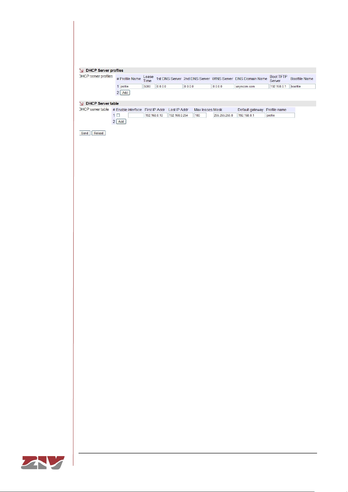
DRA-2
DRA-2 UNIVERSAL COMMUNICATION NODE 80/158
USER GUIDE - Rev.5 (January 2018)
FIGURE 33 DHCP Server menu
5.10.1 DHCP Server Profiles
Creating profiles allows the creation of sets of parameters that are common to different
instances of the DHCP server, operating on different interfaces.
The parameters for configuring a profile are:
• Lease time. This allows the time in seconds to be specified for an IP address to be
assigned following a request from a DHCP client. After the indicated time, if the
DHCP has not requested a renewal, the IP address will be considered available for
dealing with new requests.
• 1st DNS server. This allows the specification of the primary DNS server IP
address which the DHCP server will provide to the DHCP client. If left blank
(0.0.0.0) no information on DNS servers will be sent to the client.
• 2nd DNS server. This allows the IP address of a secondary DNS server to be
specified to the DHCP client. If left blank (0.0.0.0) this means that no information
will be sent to the client in this respect.
• WINS server. This allows the IP address of the WINS server to be established,
which will be notified to the DHCP client. WINS is a names resolution system
owned by Microsoft for equipment executing the Windows operating system.
• DNS Domain Name. This establishes the DNS domain to be used by the client for
creating its full DNS name.
• Boot TFTP Server. This establishes the IP address of the TFTP server that stores
the remote boot file, thereby allowing the client to execute a request to download
the file.
• Bootfile Name. This establishes the name of the remote boot file which the client
will request from the TFTP server configured in the preceding point.
Page 81

DRA-2
DRA-2 UNIVERSAL COMMUNICATION NODE 81/158
USER GUIDE - Rev.5 (January 2018)
5.10.2 DHCP Server Table
The configuration parameters for each interface are:
• Enable. This allows the DHCP service to be activated. Users should indicate
whether they want to use a DHCP server. DHCP Server instance will only run in
interfaces with IP static address and no DHCP Relay agent enabled.
• Interface. This establishes the interface where the client requests will be dealt with,
based on the parameters defined below.
• First IP Adrr. Allows the first IP address of the IP addresses pool managed by the
DHCP Server in this interface to be specified.
• Last IP Adrr. Allows the last IP address of the IP addresses pool managed by the
DHCP Server in this interface to be specified.
• Max leases. Allows the maximum number of IP addresses simultaneously
assigned in use to be specified.
• Mask. This establishes the net mask that will communicate with the DHCP clients.
• Default Gateway. This establishes the default router address (Default Gateway)
that will communicate with the DHCP clients.
• Profile name. This establishes which of the profiles defined in the above section
must be applied to the requests served on this interface.
5.11 VRRP CONFIGURATION
In some environments the networks connect to each other through one router. This single
router is therefore a potential failure point, which could disconnect a whole network from the
rest.
The VRRP protocol permits several routers to be presented to clients with a common single
virtual IP address, controlling the routers included in the virtual router, which is always the
one that effectively provides the service, thereby providing redundancy to clients in a
transparent manner. A master is selected from among all the routers, whereas the other
routers act as backups in the case of the master one failing.
Page 82
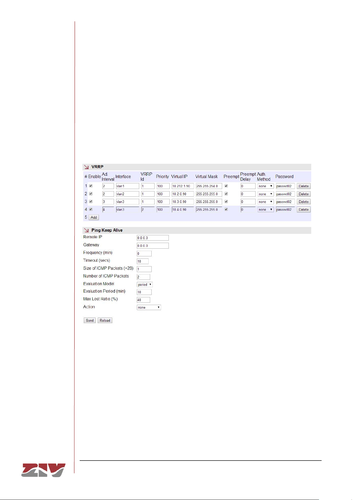
DRA-2
DRA-2 UNIVERSAL COMMUNICATION NODE 82/158
USER GUIDE - Rev.5 (January 2018)
The master router regularly sends VRRP advertisement packets to the backup routers. If
the backup routers do not receive the VRRP advertisement packets for a time that is three
times the established period, they assume that the master router has fallen and commence
a process for selecting a new master.
The equipment supports the simultaneous execution of multiple instances of VRRP
protocol. Each one is configured into an individual register, whose parameters are
described below.
FIGURE 34 VRRP menu
VRRP:
• Enable VRRP. Enables the execution of the protocol instance.
• Advertisement Interval. This establishes the time in seconds to be used for either
transmitting the VRRP advertisement packets when acting as a master or the basic
time for supervising the master when it acts as a backup router. The default value
is 1 second.
• VRRP I/F. This establishes the interface on which the VRRR protocol will be
executed.
Page 83

DRA-2
DRA-2 UNIVERSAL COMMUNICATION NODE 83/158
USER GUIDE - Rev.5 (January 2018)
• VRRP Id. The master router uses the address MAC 00:00:5E:00:01:XX, as
established in the standard protocol, where XX is the Virtual Router IDentifier
(VRID). The VRID allows a distinction to be made between the different virtual
VRRP routers operating in the network. The parameter establishes the VRID value.
If, for example, VRID 3 is specified, the MAC virtual address will be
00:00:5E:00:01:03.
• Priority. This parameter establishes the priority the router will present during the
process for selecting the master router. The range admitted is between 1 and 254.
The master router is identified due to using priority 255, once the selection process
has ended.
• Virtual IP. This establishes the virtual IP address to be used by the client to access
the routing service. It is common to all routers included in the virtual router.
• Virtual Mask. This establishes the net mask associated with the IP address of the
previous parameter.
• Preempt. This option means that if a backup router has a priority greater than the
one granted to the master router selected, the equipment will force the change and
declare it as the new master router as soon as it is included in the virtual router. A
delay can be programmed for this action through the Preempt Delay parameter.
• Preempt Delay. This allows the time in seconds to be specified for the backup
router with the higher priority to be converted into the master router.
• Authentication Method. This allows the authentication method for the physical
routers included in the virtual VRRP router to be selected. The options are PASS
(Password) and AH (Authentication Header), but it is also possible to operate
without authentication, by selecting the option none.
• Password. This establishes the password to be used in the event of selecting the
authentication use.
Ping Keep Alive:
This option is configured between a backup router and the master router, and allows
that a physical backup router to be chosen as router master when the supervision
function fails.
The Enable Wireless WAN option of the cell0 submenu of the WAN menu must be in
ON in the master router, and in VRRP in the backup router.
Page 84
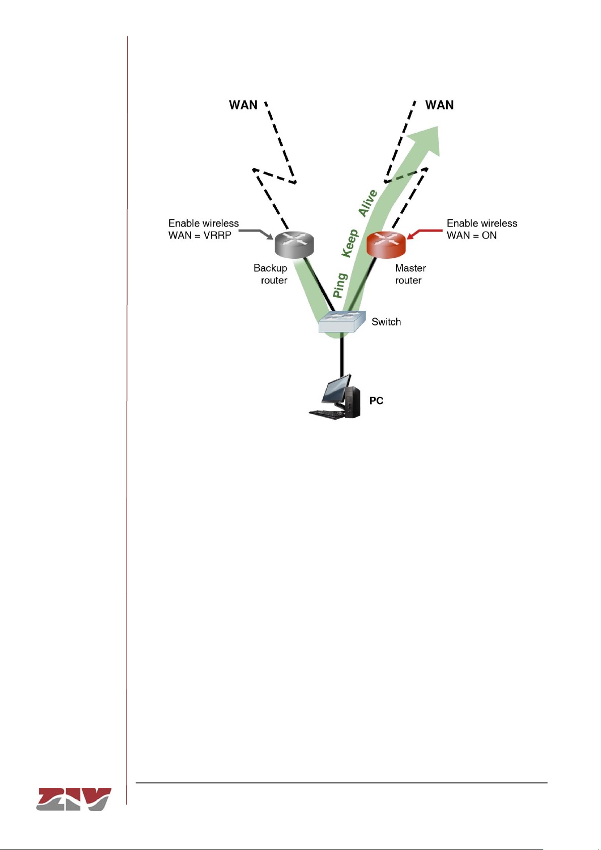
DRA-2
DRA-2 UNIVERSAL COMMUNICATION NODE 84/158
USER GUIDE - Rev.5 (January 2018)
• Remote IP. This establishes the address of the external equipment (final
destination) to be supervised. If the field value is 0.0.0.0 this means the function is
disabled.
• Gateway. The IP address of the physical master router.
• Frequency (minutes). This establishes the frequency with which the supervision
messages will be transmitted.
• Timeout (secs). This allows the maximum response time to the ICMP (ping)
packets sent by the Ping Keep Alive function to be specified. It admits a range
between 5 and 60.
• Size of ICMP packets. This allows the size of the ICMP packet to be specified.
The configuration consists of indicating the extra bytes to be added to the smallest
ICMP packet, which is, by default, 28 bytes.
Page 85

DRA-2
DRA-2 UNIVERSAL COMMUNICATION NODE 85/158
USER GUIDE - Rev.5 (January 2018)
• Number of ICMP packets. This allows the number of ICMP packets that are sent
in each verification to be specified.
• Evaluation Model. This establishes the model for the evaluation of the
accessibility test. The options are: single and period. The single model
establishes that, if some execution of the test fails, the behaviour of the equipment
is the one defined in the Action parameter. The period model establishes, by
means of the two following parameters, a test evaluation period and an admitted
failure percentage within it.
• Evaluation Period (min). When the Evaluation Model parameter is configured as
period, this establishes a period between 1 and 6000 within which a failure of the
accessibility test can be produced. All the responses to the Ping Keep Alive
packets sent in this period make the universe of samples that will be considered to
decide about the execution of Action according to the fulfilment of the criteria
established by means of the following parameter.
• Max Lost Ratio (%). This allows the maximum admitted percentage of failure in
the Evaluation period to be specified for the results of the Ping Keep Alive
messages.
• Action. This selects the desired behaviour of the equipment when the supervision
function fails. The available actions are: None (no action taken) or vrrp2master
(forcing priority to 255).
5.12 VPN CONFIGURATION
As already mentioned in the WAN tunnels section, these are a method for establishing the
opportune end-to-end links between equipment. Unlike the GRE and IPIP tunnels, IPSec
tunnels are characterised by being safe; this means the information is transmitted so that its
content cannot be accessed by others, which is particularly important if the IP network upon
which it is established is not controlled by the user, or is not public.
To create an IPSec tunnel a security association must be established in each terminator:
Tunnel IP (origin) and Remote GW (destination).
An IPSec connection between two ends requires three steps:
Establishing an IKE Security association (IKE Policy).
Establishing an IPSec Security association (IPsec Association).
Sending protected data through the IPSec connection.
Page 86
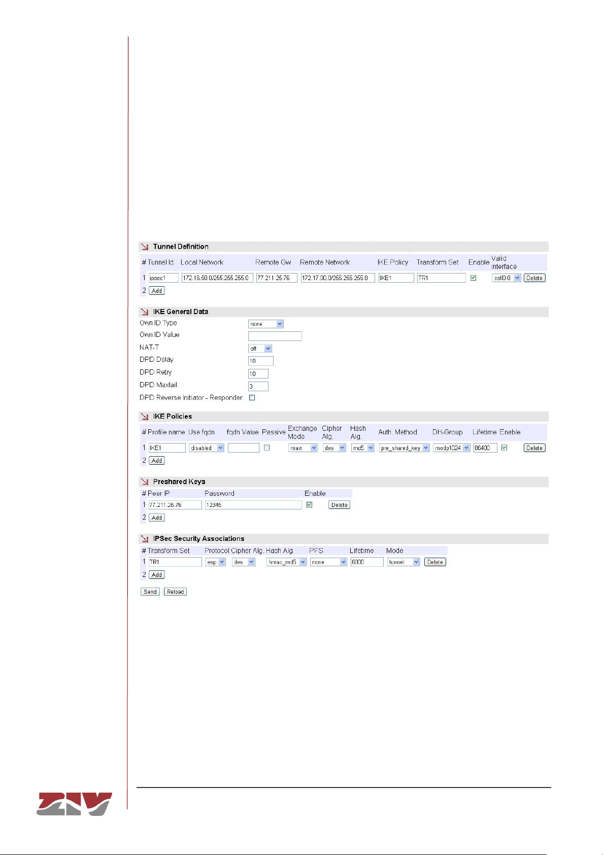
DRA-2
DRA-2 UNIVERSAL COMMUNICATION NODE 86/158
USER GUIDE - Rev.5 (January 2018)
The parameters used in each of these steps are configured as independent blocks, thereby
permitting their use in more than one tunnel at the same time and reducing the need to
duplicate configuring information.
The DPD (Dead Peer Detection) function is a mechanism for supervising operativity in the
IPSec tunnels established.
FIGURE 35 VPN menu
The sections and their configuration parameters are as follows:
Tunnel Definition:
• Tunnel ID. The identifier of the virtual tunnel device to be established.
• Local Network. This establishes the range of origin IP addresses that will be
transmitted in the tunnel. It provides a filter at the original IP address level. The any
value is accepted, as well as IP network addresses, through the IP/Mask format.
Page 87

DRA-2
DRA-2 UNIVERSAL COMMUNICATION NODE 87/158
USER GUIDE - Rev.5 (January 2018)
• Remote GW. IP address of the terminator remote equipment in the IPSec tunnel.
• Remote network. The range of IP addresses that can be reached at the remote
end of the tunnel. It is equivalent to a static route in the sense that all data
coinciding with the specified range will be sent through the tunnel. The special
value any is also accepted.
• IKE Policy. This selects the set of previously-defined parameters that will be used
for establishing the IKE Security association.
• Transform Set. This selects the set of previously-defined parameters that will be
used for establishing the IPSec Security association.
• Enable. This enables the configured tunnel. It allows the user to have configured
operative or non-operative tunnels, as wished.
• Valid Interface. This indicates the valid device identifier upon which the tunnel can
be established. It operates like an additional filter. The value any is accepted.
IKE General Data:
• Own ID Type. This indicates the type of identification to be used by the equipment.
The options are none, address entailing the use of the IP address, fqdn, which
involves using a domain (e.g. foo.domain.com), or user_fqdn, entailing the use of
an e-mail address (e.g. [email protected]).
• Own ID Value. The own identity value in the case of selecting an option other than
none in the preceding parameter.
• NAT-T. It enables the use of the option NAT-T, allowing the IPSec protocol to
function correctly when NAT services are crossed. The options are off, when the
user does not want it to be enabled or it will not be accepted if proposed by the
remote end, which is also the default value. On means that the option will be used
when detecting the presence of NAT services between both ends, and force
entails its use regardless of whether or not the presence of NAT services is
detected.
• DPD Delay. This parameter sets the time between Hello messages transmitted for
the tunnel supervision function. The valid range of values is 0 to 1200, and the
units are seconds. 0 means the supervision is not executed.
• DPD Retry. This establishes the waiting time for a response to a Hello message
transmitted, in seconds. If no response is received from the remote end within this
time, the equipment considers that a supervision failure has occurred.
Page 88

DRA-2
DRA-2 UNIVERSAL COMMUNICATION NODE 88/158
USER GUIDE - Rev.5 (January 2018)
• DPD Maxfail. The value of this parameter is the maximum admitted number of
failures to respond to a Hello message. If this maximum number is reached it is
considered that the tunnel is not available and an attempt will be made to restore it.
• DPD Reverse Initiator-Responder. This option allows the use of the DPD
supervision service with tunnels ended by Cisco equipment that execute a nonstandard variation.
IKE Policies.
• Profile name. This identifies the set of parameters being configured to establish an
IKE Security association, so that it can be used by one or more configured tunnels.
• Use fqdn (Full Qualified Domain Name). This indicates the type of identification
to be used by the equipment. The options are disabled, entailing the use of the IP
address, fqdn, which involves using a domain (e.g. foo.domain.com), or
user_fqdn, entailing the use of an e-mail address (e.g. [email protected]).
• fqdn value. This parameter determines the domain or e-mail address to be used
after selecting one of the two options indicated in the preceding section.
• Passive. When this option is executed, the equipment will not take the initiative in
establishing the tunnel and wait to receive the request from the remote end.
• Exchange Mode. This establishes the mode for exchanging codes. The mode
must be the same at both ends for the exchange to be successful. The options are
main, aggressive and base.
• Cipher alg. Cipher alg. This determines the cipher algorithm to be used for
exchanging codes. The available algorithms are DES, 3DES and AES.
• Hash Alg. This determines the hash algorithm used for authentication during the
code exchange. The available options are MD5 (Message Digest 5) and SHA1
(Secure Hash Algorithm).
• Auth. Method. This establishes the code-generating mechanism. Only the
exchange of previously-established codes is available as a method.
• DH Group. Selection of the Diffie-Hellman (DH) Modular Exponential (MODP)
group for creating codes. Group 1 (768 bits, option modp768), group 2 (1024 bits,
option modp1024) and group 5 (1536 bits, option modp1536) are available.
• Lifetime. The valid term for the security association in exchanging codes. When
the established time is up, a new association is renegotiated. The value establishes
the time in seconds.
• Enable. This indicates that the group of parameters specified can be used (active
option) or that it cannot be used (inactive option).
Page 89

DRA-2
DRA-2 UNIVERSAL COMMUNICATION NODE 89/158
USER GUIDE - Rev.5 (January 2018)
Preshared keys.
• Peer IP. This establishes the IP address of the remote tunnel equipment (Remote
GW) for which the password of the next parameter is defined.
• Password. The password is stored in this parameter.
• Enable. This indicates whether the configured password can be used (active
option) or not (inactive option).
IPSec Security Associations:
• Transform set. This identifies the set of parameters being configured to establish
an IPSec Security association so that it can be used by one or more configured
tunnels.
• Protocol. The protocol establishes which of the two types of encapsulation will be
used. ESP (Encapsulating Security Payload) provides ciphering and authentication
for each packet, and AH (Authentication Header) only provides the authentication
service.
• Cipher alg. This determines the cipher algorithm to be used for encrypting the user
data. The available algorithms are DES, 3DES and AES.
• Hash Alg. This determines the hash algorithm used for authentication. The
available options are MD5 (Message Digest 5) and SHA1 (Secure Hash Algorithm).
A third option exists, non-auth, which means the authentication is not included.
The authentication and ciphering options can be combined in different modes. If the AH
protocol is selected, only the hash algorithm choice will be taken into account, and on
the contrary if the ESP protocol is selected, the encryption is always present with the
cipher algorithm selected, and the authentication may be included with either MD5 or
SHA1, or it may not be included if the non-auth value is selected.
• PFS (Perfect Forward Secret). If the option is enabled, this means that each new
code renegotiated must be completely separated from the previous one. The
remote end must accept the PFS option for the establishment to be successful.
This option provides additional security but a greater processing load.
• Lifetime. The maximum validity time for a security association. When the
established time is up, a new association is renegotiated. The value establishes the
time in seconds.
• Mode. The IPSec provides two operating modes; the first is tunnel, which means
the original packet is completely encapsulated in an additional IP head, and the
second is transport, meaning that the original head is used without adding an
extra one.
Page 90
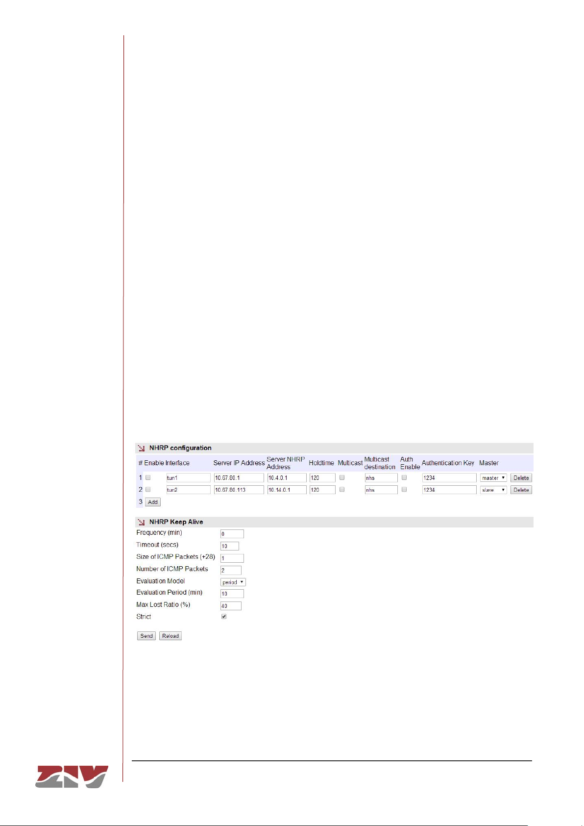
DRA-2
DRA-2 UNIVERSAL COMMUNICATION NODE 90/158
USER GUIDE - Rev.5 (January 2018)
5.13 NHRP CONFIGURATION
In meshed network environments that use interfaces with no broadcast propagation
capacity, usually known as NBMA (Non-Broadcast Medium Access), it is quite common for
a packet crossing them to be processed by several intermediate routers until it reaches its
destination or the outgoing router.
The networks in which they are created based on IP tunnels, irrespective of their type, are
ultimately collections of end-to-end links, meaning they are NBMA networks.
The NHRP protocol allows the client equipment to dynamically record the NHRP server in a
common resource, so that each client detects the presence of the other clients without
having to reconfigure, which would be necessary every time a client wanted to register or
cancel their registration. The NHRP server also acts like a protocol for resolving addresses
equivalent to the ARP, as the latter cannot be used, given that the environments are
NBMA, which in practice, facilitates more direct exchanges of traffic between NHRP clients.
The NHRP service is useful when using IP tunnels, which detect the local NHRP address
that is registered in the NHRP server.
FIGURE 36 NHRP menu
The different configuration parameters are the following:
• Enable. This enables or disabled the execution of the NHRP protocol depending
on the parameters included in the record (these are described below).
Page 91

DRA-2
DRA-2 UNIVERSAL COMMUNICATION NODE 91/158
USER GUIDE - Rev.5 (January 2018)
• Interface. Identifies the interface on which the protocol will be executed.
• Server IP Address. IP address of the equipment providing the services as the
NHRP server.
• Server NHRP Address. IP address of the NHRP server, which is the address
accessed by the local client through the respective tunnel.
• Hold time. Time during which the record is valid in NHRP.
• Multicast. This establishes whether multicast traffic can also be resolved through
the NHRP protocol.
• Multicast destination. The IP address of the equipment to which the multicast
traffic must be sent for resolution. The default value is nhs, and is equivalent to the
address specified in the parameter Server NHRP Address, i.e., the same one that
resolves unicast addresses.
• Auth. Enable. This establishes whether communication between the client and
server must include authentication.
• Authentication key. This establishes the key to be used for authenticating the
NHRP protocol.
• Master. When the NHRP protocol is established with more than one NHRP server
at a time, this parameter controls the priority, in order to determine which of the
NHRP servers the multicast traffic must be sent to. The multicast protocol is usually
a dynamic routing protocol, and so this option ensures that the presence of the
equipment is only announced to one NHRP server at any given time.
The equipment provides an optional monitoring mechanism to verify the accessibility of
NHRP terminator servers. The verification is carried out by sending packets of ICMP
protocol. If the mechanism is active, which is achieved by setting a value other than 0 in the
frequency field, the equipment automatically monitors the NHRP terminators individually.
The monitoring mechanism is in charge of selecting in each moment which of the NHRP
servers, depending on their availability and roles assigned to them, will be active for user
traffic.
Monitoring parameters are:
• Frequency (minutes). This allows the frequency of supervision message
transmission to be specified.
Page 92

DRA-2
DRA-2 UNIVERSAL COMMUNICATION NODE 92/158
USER GUIDE - Rev.5 (January 2018)
• Timeout (secs). This allows the maximum response time to the ICMP (ping)
packets sent by the Ping Keep Alive function to be specified. It admits a range
between 5 and 60.
• Size of ICMP packets. This allows the size of the ICMP packet to be specified.
The configuration consists of indicating the extra bytes to be added to the smallest
ICMP packet, which is, by default, 28 bytes.
• Number of ICMP packets. This allows the number of ICMP packets that are sent
in each verification to be specified.
• Evaluation Model. This establishes the model for the evaluation of the
accessibility test. The options are: single and period. The single model considers
only the result of a single test execution. The test will be valid provided that at least
one response is received, the number of messages sent being the number
established in the parameter Number of ICMP packets. The period model
considers for the test being satisfactory or not the result of the ICMP messages
sent within the evaluation period, taking as a threshold a percentage of maximum
admitted failure within it, both parameters being set by the user (see following
parameters).
• Evaluation Period (min). When the Evaluation Model parameter is configured as
period, this establishes a period between 1 and 6000. All the responses to the
Ping Keep Alive packets sent in this period make the universe of samples that will
be considered when making decision to change the choice of the NHRP server in
use.
• Max Lost Ratio (%). This allows the maximum admitted percentage of failure in
the Evaluation Period to be specified for the results of the Ping keep Alive
messages.
• Strict: This option allows users to inhibit the accessibility test in the presence of
traffic. If the option is not activated, the test will only be executed when the period
of time indicated in frequency without traffic has passed. When the option is
enabled, the test will be performed regardless of whether traffic is present or not.
Page 93
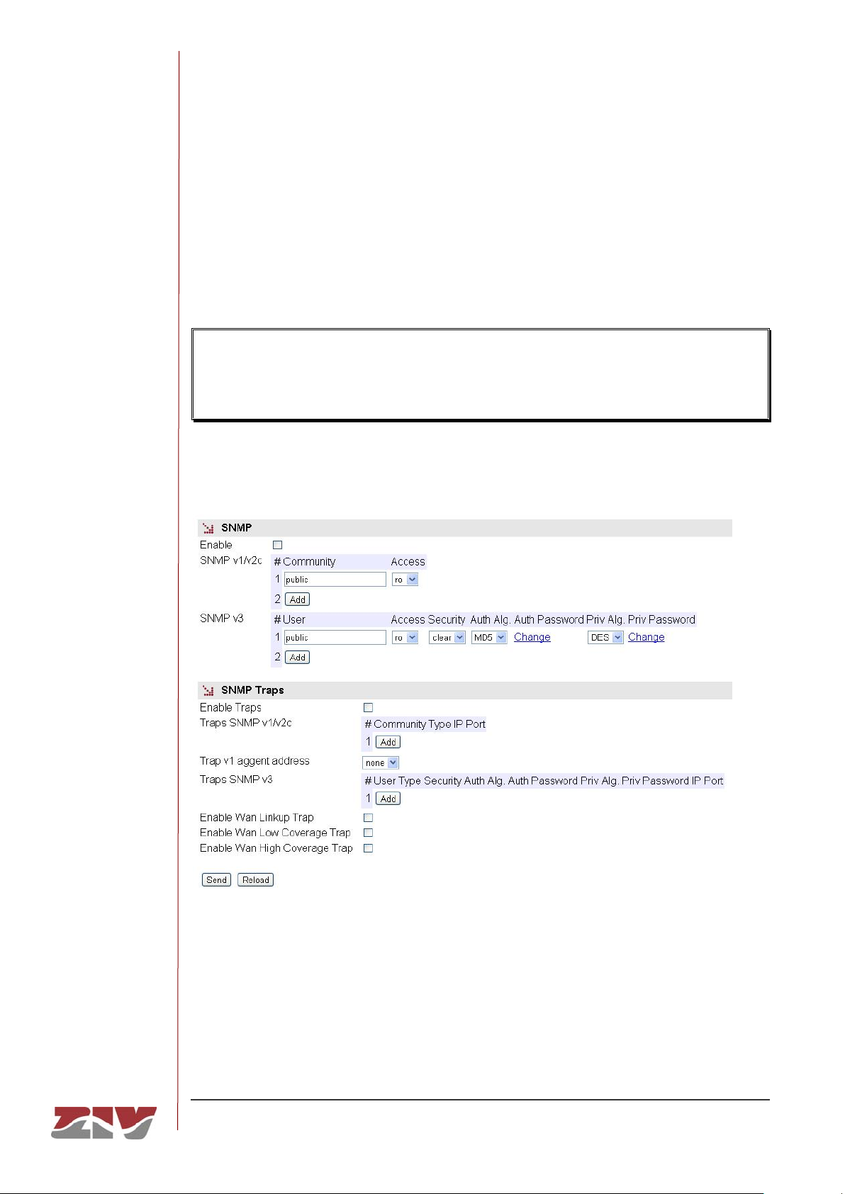
DRA-2
DRA-2 UNIVERSAL COMMUNICATION NODE 93/158
USER GUIDE - Rev.5 (January 2018)
5.14 SNMP CONFIGURATION
The equipment has an SNMP agent with the capacity to generate spontaneous messages
to control equipment, based on that protocol.
The agent admits the emitting of messages based on the SNMPv1 [3], SNMPv2c [4] and
SNMPv3 protocol, and the selection of the type of message, trap and inform.
Changes made to the SNMP agent configuration will only be active after RESETTING
the equipment. The Apply command is not sufficient, and so the changes must
previously be saved using the Save command before requesting the reboot.
FIGURE 37 SNMP menu
Page 94

DRA-2
DRA-2 UNIVERSAL COMMUNICATION NODE 94/158
USER GUIDE - Rev.5 (January 2018)
The configuration parameters are:
SNMP:
• Enable: Enables/disables the execution of the SNMP agent. The agent is operative
when the option is selected.
• Community: Parameter associated with SNMPv1/v2c. Tabulate information that
allows several operating profiles to be defined, including the rights of access
(Access) associated with each one, read only rights (ro) or reading/writing rights
(rw). The profiles are called communities.
• User: Parameter associated with SNMPv3. Tabulate information that allows the
users, including the privileges and the operating mode associated with each user,
to be defined. That is to say, the rights of access (Access), read only rights (ro) or
reading/writing rights (rw), and the way in which the data transference (Security)
will be carried out, without encryption (clear), authentication (auth) or authentication
and encryption (priv).
In case of authentication transmission (auth), it is necessary to select the type of
algorithm (Auth Alg.), MD5 or SHA, and establish the authentication password
(Auth Password). The password establishes the word to be used to generate the
authentication information. The authentication word must be known by the receiver
in order to be able to verify the authenticity of the identity of the transmitter.
In case of encrypted transmission (priv), in addition to select the type of
authentication algorithm (Auth Alg.) and authentication password (Auth Password),
it is necessary to select the cipher algorithm (Priv Alg.), DES o AES, and establish
the cipher password (Priv Password).
The password is not shown for security reasons and so when it is changed
(Change option), it must be entered twice.
Once the Password is introduced from the Change option, execute the send
command of said option, and then, if you want the password to be applied and
saved in the equipment, DO NOT forget to execute the apply and save
commands from the main menu tree.
Page 95

DRA-2
DRA-2 UNIVERSAL COMMUNICATION NODE 95/158
USER GUIDE - Rev.5 (January 2018)
SNMP Traps:
• Enable Traps: Enables/disables the generation and transmission of spontaneous
messages by the SNMP agent. The agent will send the traps selected by the user
when the different events occurred.
• Traps SNMPv1/v2c: Tabulate information allowing several destination equipment
for the traps to be defined.
For each of the spontaneous SNMP message addressees, a profile must be
provided, which must be included in the spontaneous message, the SNMP protocol
version with which it will be coded, the IP address of the addressee and the UDP
port to which the messages will be sent. The default value established in the
standard is port 162. It can be changed to adapt to the operating data of each
addressee.
The transmission of the messages in a confirmed (inform) way is only accepted for
the v2c and v3 versions of the protocol.
• Trap v1 agent address: This establishes the IP address the agent will
communicate as being its own when sending spontaneous messages. This
parameter is only used to create the traps when using SNMPv1.
• Traps SNMPv3: Tabulate information allowing several destination equipment for
the notifications to be defined.
The receivers are identified by means of their IP address and the UDP port to
which the notifications are to be sent. The standard UDP port for the SNMP
notifications is the 162, being the value by default.
The Type control is used to establish whether the transmission of the notifications
is carried out in an unconfirmed (trap) or confirmed (inform) way.
5.15 STP
The Spanning Tree Protocol, in both its original version (STP) and the improved version
(RSTP) has the objective of identifying potential loops in level 2 networks, so that the
different equipment can communicate with each other and establish whether the different
interfaces in each will be active for switching client traffic, or on the contrary, whether they
will be used as backups in case of potential topological changes. The final result is that the
active interfaces of each equipment end up forming a tree structure with no loops from the
root equipment.
Page 96
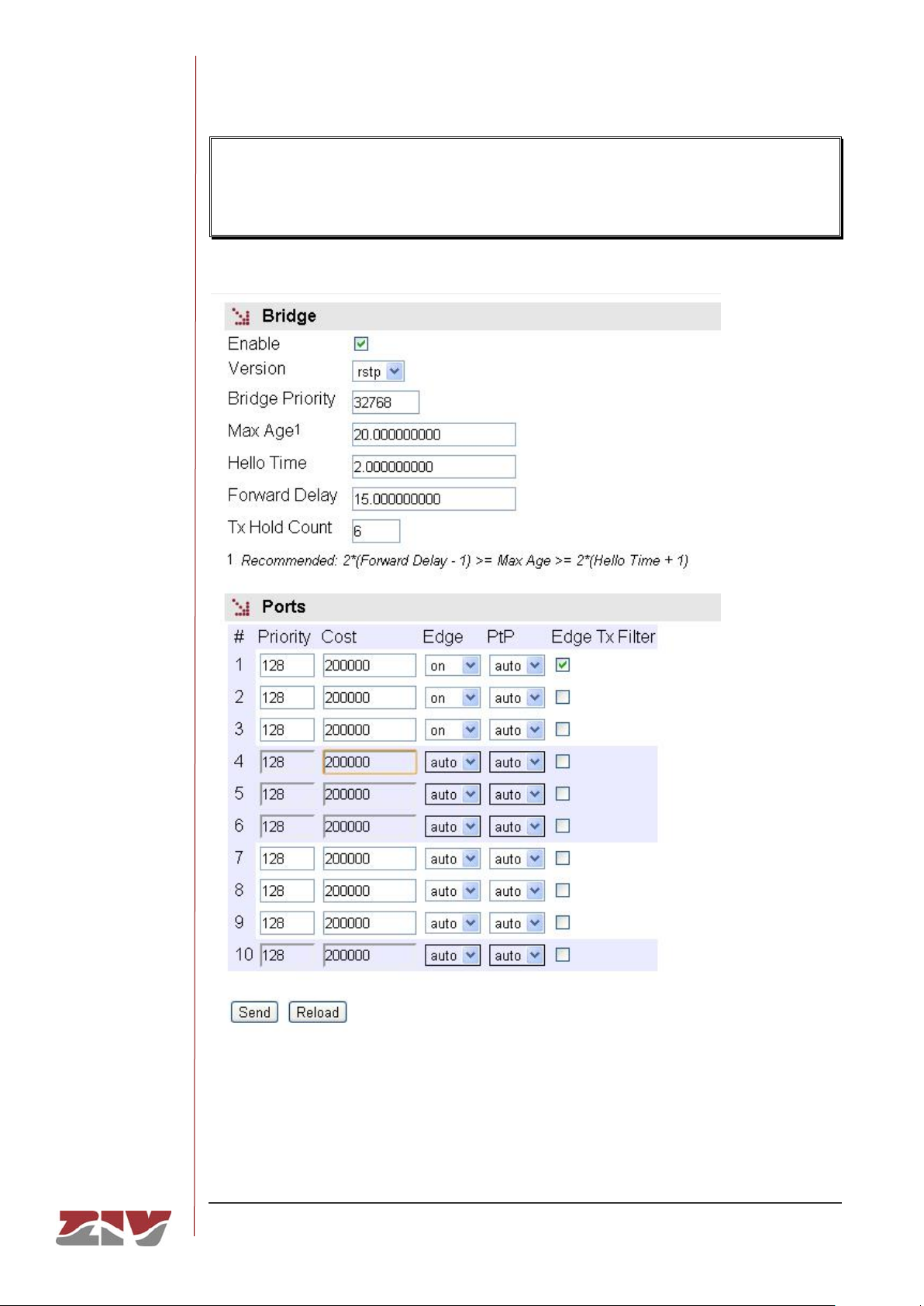
DRA-2
DRA-2 UNIVERSAL COMMUNICATION NODE 96/158
USER GUIDE - Rev.5 (January 2018)
If the equipment is to be included in a level 2 network interconnected to other switching
equipment and there is a possibility of loops being created (depending on the connection
topology), it is ESSENTIAL to activate the Spanning Tree Protocol.
FIGURE 38 STP Menu
Page 97

DRA-2
DRA-2 UNIVERSAL COMMUNICATION NODE 97/158
USER GUIDE - Rev.5 (January 2018)
The specific equipment configuration parameters are:
• Enable. A simple checkbox parameter to indicate whether the STP must be
executed or not.
• Version. This establishes which of the possible protocol versions will be executed.
STP or RSTP (Rapid STP).
• Bridge Priority. This sets the priority of the equipment communicating with the root
equipment.
• Max Age. The maximum time during which the equipment considers the last BPDU
message received as valid. In the case of the stipulated time expiring, the
equipment assumes there has been a topological change and initiates the
topological change communication process. The default value is 20 seconds, and
the range admitted is between 6 and 40 seconds.
• Hello Time. This parameter establishes the time between sending BPDU
messages (the STP protocol messages). The default and maximum value is
2 seconds.
• Forward Delay. This parameter is the maximum period of time for an interface to
be in the listening and learning states. The default value for this period is 15
seconds, and the range admitted is between 4 and 30 seconds.
• Tx Hold Count. This establishes the maximum number of BPDU packets that can
be transmitted in one second. The default value is 6 and the admitted range is
between 1 and 10.
The configuration parameters for each port are:
• Priority. This establishes the port priority. If there are two or more ports with one
cost, the priority allows the root port of the equipment to be selected.
• Cost. This establishes the cost associated with the port. Selecting the root port of
the equipment is directly related to the lower cost of the different ports in relation to
the root equipment.
• Edge. This parameter indicates the operating mode of the interface with respect to
the STP. Interfaces connected to client equipment, i.e., equipment that is not level
2 switching equipment and which therefore does not execute STP or give rise to
the creation of loops may be booted directly to a traffic transmission situation
(on mode), and on the contrary interfaces that are directly connected to level 2
switching equipment and are therefore prone to close loops must be booted in the
accept user traffic mode (off mode). A third mode exists, auto, in which the
Page 98

DRA-2
DRA-2 UNIVERSAL COMMUNICATION NODE 98/158
USER GUIDE - Rev.5 (January 2018)
equipment determines the presence or absence of level 2 switching equipment
connected to the interface. This is useful in cases in which the type of equipment to
be connected is not known, but the processing of traffic is slowed down.
Even when the Edge parameter is on, the switch maintains activated the detection
of other switch connection to the interface, so operating state can become off.
The operating mode of the interface can be checked in the STP statistics section.
• PtP. The PtP parameter establishes whether the interface is directly connected to
other level 2 switching equipment on an end-to-end link (on value) or not (off
value) but the equipment is also capable of detecting that situation (auto value). If
the equipment indicates that a link is PtP, this allows greater speed in protocol
convergence, and the agreement process on changing the state of a link from
designated to non-discarding (operative for user traffic) is speeded up.
• Edge Tx Filter. When the RSTP protocol is executed, this parameter allows the
user to enable a filter that avoids the transmission of STP BPDU packets in the
interfaces operating in edge mode. This parameter is only effective when the
operating state of the interface is edge, and this situation is only possible when the
Edge parameter is configured as on or auto.
Switch interconnection using interfaces with Edge_Tx_filter active lead to
switches being unable to detect the connection as part of a loop.
5.16 NTP CONFIGURATION
The equipment has an NTP client, meaning that it can synchronise time-related information
by accessing NTP servers. The NTP [5] protocol is a standard that is widely used in
TCP/IP-based networks. It admits the use of several NTP servers simultaneously, and the
option of using authentication.
Page 99
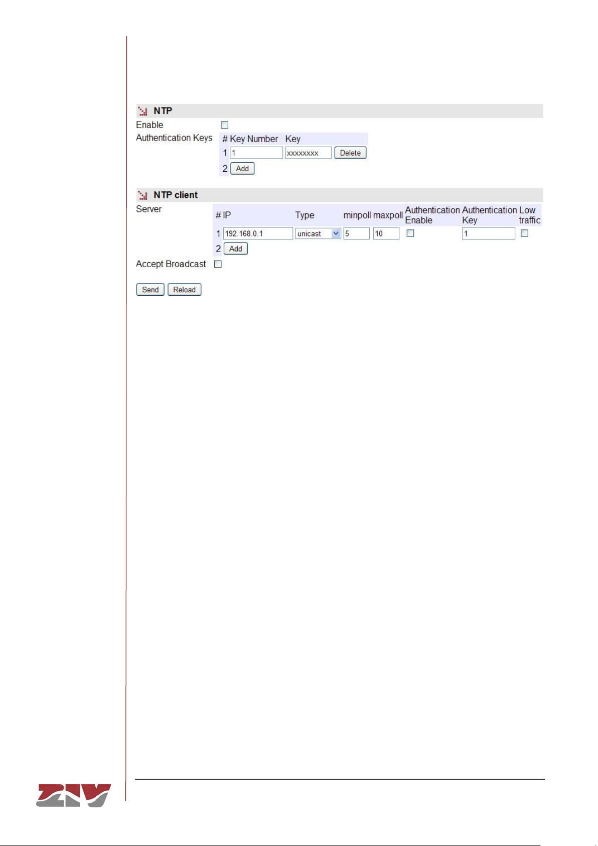
DRA-2
DRA-2 UNIVERSAL COMMUNICATION NODE 99/158
USER GUIDE - Rev.5 (January 2018)
FIGURE 39 NTP menu
The usage parameters are:
• Enable. Enables/disables the execution of the NTP client. The client is operative
when the option is selected.
• Authentication keys: Tabulate information allowing the definition of different
authentication codes to be used subsequently in communicating with the different
NTP servers.
• Server: Tabulate data that includes the NTP servers access data. Each row
contains data related to one NTP server.
• Accept broadcast: This establishes whether the NTP client will accept messages
transmitted with broadcast-type NTP messages.
For each of the NTP servers configured, an IP address must be provided, as well as the
type of IP message it will use to access the individual server (unicast) or collective Server
(manycast), the minimum time between requests, with the parameter establishing the
exponent of the power of 2 in seconds; the maximum time between requests, also as the
exponent of the power of 2 in seconds, and a selection option that determines whether
authentication should be used, in which case it is necessary to indicate which previouslydefined code the client with the server in question will use.
Page 100
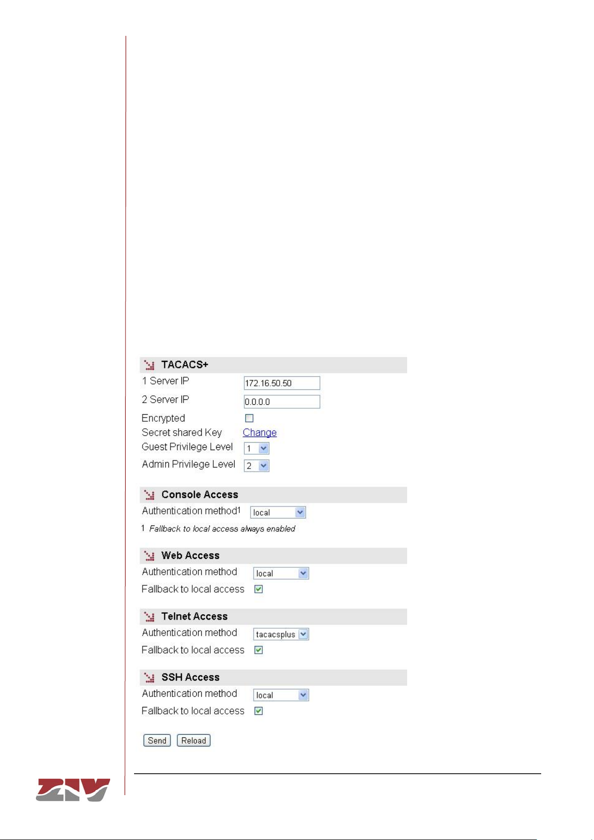
DRA-2
DRA-2 UNIVERSAL COMMUNICATION NODE 100/158
USER GUIDE - Rev.5 (January 2018)
5.17 ACCESS CONFIGURATION
The equipment offer users several means of access: operating console, access via http
server (web) and telnet.
Local users predefined in the system are always present but an external resources can be
used to validate users for different types of access, for which reason the user database is a
centralised and independent resource with respect to the equipment itself. For this purpose
the equipment has a TACACS+ client.
TACACS+ (Terminal Access Controller Access Control System) is a remote authentication
protocol used to manage access to servers and communication devices; it provides separate
authentication, authorisation and registration services.
FIGURE 40 Access menu
 Loading...