


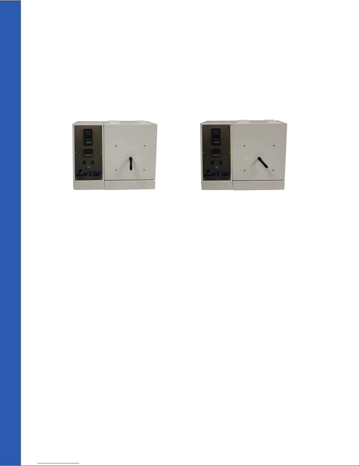
Hot Spot 110
User Guide
Zircar Zirconia, Inc. www.zircarzirconia.com
R-110M-01 Rev00

Table of Contents
Sections:
1. Safety ..................................................................................................1
2. Important Information..................................................................3
3. Unpacking/Initial Inspection.......................................................3
4. Installation/Assembly.....................................................................4
5. Operating the Furnace...................................................................5
6. Setting up the Controlers.............................................................6
7. Maintenance......................................................................................8
8. Troubleshooting...............................................................................9
9. Contact Us.......................................................................................11
Appendices:
A. Hot Spot 110 Key
B. Electrical Schematic and Parts List
C. REX-P48 Temperature Controller Conguration
D. REX-P48 Temperature Controller Patterns (Programs)
E. CL100L Over-Temperature Controller Conguration
F. SCR
G. REX-P48/96 Series Programmable Temperature Controller Operation
Manual
H. REX-P48/96 Operation Manual Supplement
I. CB100L/CB900L Limit Controller Initial Setting Manual
J. CB100L/CB900L Limit Controller Instruction Manual
K. Model 18 and Model 36 Series Solid State Power Controls Installation and
Operating Notes
L. Programmable Controller Tuning
R-110M-01 Rev00

1. SAFETY
Please read and understand all safety hazards and warnings prior to using your Hot Spot 110
furnace. If you have any questions about this section please contact Zircar Zirconia, Inc. BEFORE
start up.
ELECTRICAL WARNINGS
1. The Hot Spot 110 is designed to be powered by a single phase circuit breaker or fuse protected
grounded outlet and is supplied with a cord with a plug appriopriate for the design voltage.
• Operating with an improper power supply could cause the cord to overheat and cause a re.
• No other device should be operated on the circuit used by the furnace. The furnace works
best over the long run if supplied with a constant voltage.
• Please refer to the furnace nameplate to verify your Hot Spot power requiprements and
reference the chart below.
Model Voltage Amperage
Hot Spot 110 110-120 20
Hot Spot 110 220-240 10
Hot Spot 110L 110-120 20
Hot Spot 110L 220-240 10
2. Disconnect all power from the furnace before opening any part of the Hot Spot 110 cabinet.
Failure to disconnect the power supply can result in electrocution. Unplug the power cord to
disconnect the power.
3. The Hot Spot 110 is electrically resistance heated by exposed heating elements. NEVER TAMPER
with the safety cut o switch. The safety cuto switch cuts o power to the heating elemenets
when the door is opened (see appendix A #8).
BURN/FIRE WARNINGS
1. Do not locate the Hot Spot 110 near combustible materials. Select a safe location to install the
furnace.
• The furnace door opens up and away from the operator and can be opened when very hot. If
opened while hot, the door will radiate heat over the top of the furnace. Combustibles
located in the path of this radiated heat may catch re.
1

BURN/FIRE WARNINGS (CONTINUED)
2. Do not locate the Hot Spot 110 on a ammable surface.
• The Hot Spot 110 is equipped with a cooling fan which will maintain the shell at a safe
temperature. Objects removed from the Hot Spot 110 furnace chamber while hot may cause a
re if placed on a ammable surface.
• Zircar Zirconia, Inc. recommends that when hot objects are removed from the furnace they
always be placed on a trivet appropriate for the temperature.
3. Avoid touching the Hot Spot 110 powder coated steel shell when the furnace is in operation. The
metal may become hot and could cause a burn injury with extended contact.
4. Use heat resistant gloves and darkened eye protection when unloading a hot object from the
Hot Spot 110 furnace chamber. Handling hot objects with bare hands will result in serious burns
of the skin. Radiant heat may cause occular damage if not wearing darkened eye protection.
HEATING ELEMENT WARNINGS
1. Always use eye protection and gloves when loading and unloading the furnace and when
handling the heating elements.
2. The Hot Spot 110 is heated with molybdenum di-silicide (MoSi2) heating elements which form a
protective silica glaze over the surface of the element. Elements which have been operating at a
high temperature for a prolonged time and then cooled down may have internal stresses which
can cause the protective silica glaze to splinter into small fragments. There have been instances
where heating elements that have been cold for several days have emitted a shower of ne glaze
particles when touched. If a silica glaze shower does occur, vacuum up the silica akes before ring again. The akes could melt into the oor causing premature insulation failure. The elements
are not metal and they are as fragile as glass.
GAS PORT WARNINGS
The following warnings apply if your Hot Spot 110 is equipped with the optional gas port:
1. Do not introduce any ammable atmospheres into the Hot Spot 110 chamber. This may cause an
explosion, possibly leading to serious injury or death.
2. Always provide good ventilation in the immediate and surrounding areas whenever using the
optional gas port to introduce inert gasses into the Hot Spot chamber. Accumulated gasses such
as nitrogen and argon can be inhaled and result in asphyxiation.
3. When operating the Hot Spot 110 at 1600 °C in an atmosphere of pure argon and pure nitrogren,
the life of the electric heating elements may be reduced to a few weeks as compared to their
normal life which can be in excess of two years. A discussion of the temperature limits of the
MoSi2 elements in various atmospheres can be found at www.kanthal.com and
www.isquaredrelement.com.
2 R-110M-01 Rev00

2. IMPORTANT INFORMATION
1. Your Hot Spot 110 has been “broken in” prior to shipment by being run through a series of high
temperature calibration cycles and an element glazing pattern. No additional pre-ring is needed
before use.
2. Allowing the Hot Spot 110 to naturally cool from maximum temperature to ambient temperature is
preferred.
3. The life of the Hot Spot 110 lining and door insulation will be greatly extended by keeping the door
closed while the Hot Spot 110 is hot. Close the door as soon as possible if the furnace must be opened
during use.
4. The lightweight ceramic ber thermal insulation is very porous and will wick contaminants. It is
important that materials which may contaiminate and or react with the Hot Spot 110 insulation lining
be removed prior to heating the furnace chamber. Typical contaminates are:
• Previously processed material remnants.
• Glaze which has fallen from the heating elements.
5. An appropriate ring setter should always be used to protect the Hot Spot 110 oor since most
materials will completely melt at the temperatures your furnace is capable of reaching.
6. Your Hot Spot 110 has been congured by Zircar Zirconia, Inc. with control parameters which have
been determined to be suitable for the best control over the widest range of temperatures. These
parameters are listed in appendix C of this manual.
7. Your Hot Spot 110 has been pre-programmed with two programs, called patterns, which are listed in
appendix D of this manual.
3. UNPACKING / INSPECTION
The Hot Spot 110 furnace has been carefully packaged to prevent shipping damage. Upon receiving
the furnace system:
1. Carefully inspect the delivery for possible shipping damage.
• Report damage claims to the transportation company immediately. Retain all packaging
materials.
3

UNPACKING / INSPECTION (CONTINUED)
2. Unpack the crate and any associated packages. Inspect the contents. Retain packaging materials
until all components have been found. A standard Hot Spot 110 furnace system consists of the
following components:
• One furnace complete with insulation, controllers, heating elements and door in place.
• One owner’s manual.
• One power cord.
• One alumina insulation setter plate.
• One box of Precision Temperature Contorl Rings (PTCR) with temperature chart.
3. Place the furnace on a sturdy, level table near an electrical outlet appropriate for the Hot Spot
110 ordered.
4. Remove the packing material from under the roof and in the heating chamber.
• Remove the roof cover by unscrewing the bolts at the rear of the unit and the front bezel.
Remove the foam packing material. Replace the roof cover (see appendix A #6, 9, 10).
• Open the Hot Spot 110 door by turning the handle and lifting outwards and upwards until it
catches on the latch (see appendix A #7). Remove the packing material from the heating
chamber. Be careful not to touch the heating elements.
IMPORTANT! - ALL PACKING MATERIAL MUST BE REMOVED
BEFORE PROCEEDING!
3. Inspect the furnace interior, heating elements and door for damage.
4. INSTALLATION / ASSEMBLY
1. With the furnace door open, install the setter plate by carefully placing it onto the oor of the
furnace centered between the elements.
2. Close the door using two hands. Lift the door up and back with one hand, disengage the
hold up latch with the other hand and gently guide the door down into the closed position.
The safety cut o switch located on the lower right side of the control panel (see appendix A #8)
will audibly click into place.
3. Plug the female end of the power cord into the power cord receptacle on the back of the furnace
(see apendix A #12).
4. Plug the male end of the power cord into an appropriate wall outlet.
5. Congratulations! Your Hot Spot 110 is ready to be powered up.
4 R-110M-01 Rev00
5. OPERATING THE HOT SPOT 110
Preparing for the Firing
1. Open the Hot Spot 110 door by turning the handle 45° in either direction from the downward closed
position and lifting outwards and upwards until the door catches on the hold-up latch. Avoid over
rotating the door handle.
Door Handle in Closed Position Door Handle in Open Position
2. Load the Hot Spot 110 by placing the material to be red (ware) or tray on the setter plate. Maintain
at least 1/2 inch between the heating elements and the ware or tray to promote uniform heating and
to prevent element damage.
3. Close the Hot Spot 110 door using two hands by lifting the door up and back with one hand,
disengaging the hold up latch with the other hand and gently guiding the door down into the closed
position.
4. Lock the door by turning the handle into the down pointing, closed position.
5. Switch the green power switch to the ON position (see appendix A #3). The light will turn green, the
fan will come on and the controllers will start up.
6. Push the PTN1/PTN2 button on the program controller to choose the desired pattern (program) to be
run (see appendix A #20). To review the pattern, press the SET button repeatedly to scroll through the
program (see appendix A #24). See section 6 for pre-programmed patterns.
Starting a Firing
1. Press and hold the reset button (RST) on the Over-Temperature Controller until the red OUT LED light
turns o (see appendix A #37 and 35).
• NOTE: The Over-Temperature Controller must be manually reset whenever the power to the
Hot Spot 110 is shut o. Power shut-o includes: switching the green power button to the
o position, unplugging the unit, and power failure.
2. Press the reset button (see appendix A #22) on the Program Controller.
3. Press the heat switch on. The contactor will switch on with an audible click (see appendix A #4). The
green HEAT ON light will illuminate (see appendix A #5).
5

OPERATING THE HOT SPOT 110 (CONTINUED)
4. Press the RUN button on the Program Controller to start the program (see appendix A #19).
• We recommend that you are present during the initial part of the program to be sure the Hot
Spot 110 is heating up and following the program. During this period you may observe the actual
temperature (PV) overshooting the desired set point (SV), this is normal since the elements
deliver a lot of power very quickly when rst heated and the Type B thermocouple has a nearly
constant output at low temperatures. The dierence between set point and actual temperature
will minimize and nearly coincide by about 200°C or lower. See appendix A #15 and #16 for PV
& SV)
6. SETTING UP THE CONTROLERS
OVER TEMPERATURE CONTROLLER
Over temperature protection is provided by the Over-Temperature (OT) Controller. If the temperature in the furnace (PV), indicated by the green number, exceeds the set point (SV), indicated by the
orange number, power to the elements will automatically be turned o and the furnace will rapidly
cool as fast as it can shed heat. The furnace is shipped with the OT limit set 10°C over the max rated
furnace temperature. We recommend the Over Temperature Controller be remained unchanged
unless it is critical for your process that the OT limit be revised. If you MUST reduce the OT limit, it can
be reduced as follows:
1. Press the (SET) button. The rightmost digit will be highlighted in the
lower, orange display (see appendix A #36).
2. Press the v or ^ button as needed to set the rightmost digit (see appendix A #40 and 41).
3. Press the <RST button to advance to the next digit (see appendix A #37).
4. Press the v or ^ button to set that digit.
5. Repeat 3 or 4 for the other 2 digits.
6. Press the (SET) and PHLD will display.
7. Press the (SET) and TIAE will display.
8. Press the (SET) so that the current temperature of the furnace appears in the upper, green display
and the over temperature set point appears in the lower, orange display.
9. Detailed instructions are contained in the factory instructions located in appendix J.
PROGRAM TEMPERATURE CONTROLLER
The temperature inside the Hot Spot 110 is controlled by a REX P48 Programmable Temperature
Controller. This device can store two patterns of (up to) eight steps each which can be linked into a
single (up to) 16 step pattern. Each step has a starting temperature and ending temperature or set
point (SP) and a duration or ramp time (RT). The starting temperature of the rst step is the actual
temperature of the furnace when the pattern is started. The starting temperature of subsequent
steps is the ending temperature of the previous step. The furnace is shipped with the two patterns
listed in the table below, unless otherwise specied when your order was placed (see appendix D).
6 R-110M-01 Rev00

Hot Spot 110 Pre-Loaded Programs
PTN 1 SINTER S1 S2 S3 S4 S5 S6 S7 S8
SP 1530 1530 200 END
RT 2:30 2:00 4:00
PTN 2 CLEAN S1 S2 S3 S4 S5 S6 S7 S8
SP 1350 1600 1600 END
RT 1:00 1:30 1:00
You can edit both patterns to suit your needs as follows:
1. Press the PTN1/PTN2 button to select the desired pattern (see appendix A #23).
2. Press the SET button so the step 1 ending temperature set point is displayed (see appendix A #24).
3. Press the Hold (down) or Step (up) buttons to raise or lower the temperature set point of the program
(see appendix A #31).
4. Press the SET button to display the time for step 1.
5. Press the Hold (down) or Step (up) buttons to raise or lower the time interval for step 1 in hours
and minutes as HH.MM.
6. Press the SET button to move to the temperature set point for the next step.
7. Repeat 3, 4, 5, and 6 for each step in the pattern.
8. Press the END button at the end of the last step (see appendix A #30).
Programming Tips:
• Every pattern must have an END statement. Programming an END (per step 8 above) will cause the
furnace to power o at the end of that step.
• Step 1 of the pattern will start at the actual temperature of the furnace when the pattern is run.
Example: If the end point and time of step 1 is 1000 °C and 1 hour respectively and the temperature at
startup is 100 °C, then the furnace will heat up at a rate of 900 °C per hour to 1000 °C.
• Detailed programming instructions are contained in the OEM instructions located in appendix G.
• To prevent the furnace temperature from overshooting the soak temperature, the ramp rate
should not exceed 5°C per minute during the last 50 degrees of ramp. Additionally, if too fast a
ramp rate is selected, and if the soak temperature is near the over temperature limit, there is a good
chance that the furnace will be shut down by the over temperature controller.
• All eight steps do not need to be utilized for every pattern
7

7. MAINTENANCE
Fan Filter
The maintenance frequency required by the Hot Spot 110 furnace will vary depending on how it is
used. During normal use it is important to keep the fan lter clean and remove contaminates from
the furnace chamber before each ring. See appendix A #14.
Insulation
It is normal for the ceramic ber insulation to crack. As long as the insulation remains in place the
furnace will operate normally. Eventually the insulation will need replacement. Please contact
Zircar Zirconia, Inc. for parts and instructions to replace the furnace lining. Consider returning the
furnace to our factory for relining.
Thermocouple
The type B thermocouple will age with time and should be calibrated on a regular basis. The
complimentary box of single use Precision Temperature Control Rings (PTCR) included with the Hot
Spot may be used as furnace calibration check or as a record of an individual ring. For a calibration
check re a PTCR ring to 1500 C, ramping at 120 C/hour during the last 200 C of the ramp. Hold at
1500C for one hour. Measure the outside diameter of the red ring and compart to the chart to
determine the actual soak temperature. Large dierences (>10 C) between measured ring and
program temperature indicate that the thermocouple is out of calibration and should be replaced.
For video instructions on how to replace the thermocouple go to
www.zircarzirconia.com/technical-documents/procedure-replacing-hotspot-thermocouple/.
Heating Elements
Eventually a heating element will require replacement. Elements are very fragile and can be broken
while changing other elements. Therefore it might be best to replace all four elements at one time if
they show signs of deterioration. If only one element is to be replaced, take care to prevent any
stressing of the terminals of the other elements.
Replace heating elements as follows:
1. Unplug the furnace.
2. Remove the top cover by unscrewing the 2 rear bolts and opening the furnace door and
unscrewing the front bezel bolt (see appendix A #9, 10, and 6).
3. Unclamp the aluminum braid from the element terminal.
4. Remove the used element by lifting its holder straight up and out of the furnace.
5. Loosen the clamping bolt on the element holder and remove the used element. Take care not
to break the insulation tab which ts between the terminals of the holder. Replace any broken
tabs.
6. Unpack a new element by placing it on a rm surface and cut the tape between the terminal and
the wooden brace with a razor blade or Exacto knife. Carefully remove the tape and the wooden
brace taking care not to ex the element.
7. Reassemble the element holder with the new element so that the element terminals extend out
of the holder the same length as originally set.
8 R-110M-01 Rev00

8. Place the element / holder assembly into the furnace.
9. Replace the braided contact straps if they show signs of wear. Otherwise, reinstall the used strap.
10. Pre-form new contact straps to t the terminals by bending them over an old terminal or some
other 6mm solid round mandrel.
11. Take care placing the spring clamps onto the contact straps. Keep the ends of adjacent spring
clamps as far away from each other as possible so they do not short out against each other. Do not
torque the element terminals when replacing the clamps.
12. Replace the top cover.
8. TROUBLESHOOTING
1. The controllers do not turn on when the power switch is turned on.
• The power cord is not plugged in.
• The fuse has blown.
• The controller has failed and needs to be replaced.
2. The programmable controller or over temperature controller do not indicate temperature.
• If either controller is ashing oooo then the thermocouple to that controller is broken and
must be either repaired or replaced.
• Check the control thermocouple and terminal block connections for a loose connection.
• Check the control thermocouple lead wire at the back of the controller for a loose connection.
3. The furnace does not heat and the HEAT ON indicator (see appendix A #5) does not illuminate.
• Check that the Heat switch is in the on position which is position l (see appenx A #4).
• Check that the Over Temperature Controller has been reset by seeing the red OUT LED light
is o.
• Unplug from the power source. Check the main power fuse inside the controller cabinet by using
an Allen key to remove the side panel. Locate the power fuse on the back wall adjacent to the side
panel and remove with a fuse puller. Measure the fuse with a volt meter for continuity or high
resistance. If the fuse is good the meter will beep for continuity or show a low resistance.
4. The furnace does not heat and the HEAT ON indicator is illuminated.
• Check that the furnce temperature (PV) displayed in green on the Over-Temperature Controller is
not reading higher than the number displayed in orange (SV) (see appendix A #32 and #33). If the
PV exceeds the SV, one of the following is possible:
-The overtemperature thermocouple is reading falsely hot. Replace the thermocouple.
-The overtemperature SV is set too low and may need to be reprogrammed.
-The furnace is overheated, wait for it to cool.
• Check that the overtemp controller is reset. If unsure as to whether or not it is reset, try to reset it
again. The OUT light above the <RST button should be o (see appendix A #35).
9

TROUBLESHOOTING (CONTINUED)
• Check that the temperature controller is in run mode.
• Check that the pattern setpoint is above the actual furnace temperature.
• Check for broken elements. Broken elements can be hard to see, there can be a hairline
crack anywhere including in the element shank hidden by the roof insulation.
- To nd a bad element, remove the furnace from the power source and remove one of the
power supply wires to the element contact braids. Use an ohm meter across the braids where
they connect to the supply wires. If any of the elements are bad the meter will show high
ohms. Find the bad element or connection by measuring each element individually. If the
elements and braid connections were all good the meter should show low ohms which indicates a dead short.
5. The over temperature controller alarms during a ring.
• Check the over temperature controller set point.
• Check the over temperature controller thermocouple.
• Check the over temperature controller thermocouple wiring and connections.
6. The furnaces does not follow the desired pattern.
• Check that the temperature controller is in run mode.
• Verify the pattern.
• Verify the temperature controller conguration.
• Check for a blown SCR fuse inside the control cabinet.
- Unplug from the power source. Use an Allen key to remove the side panel. Locate the SCR
fuse on the very top of the back wall and remove with a fuse puller. Measure the fuse with a
volt meter for continuity or high resistance. If the fuse is good the meter will beep for
continuity or show a low resistance.
10 R-110M-01 Rev00

9. CONTACT US
Business Hours: 8 AM to 5 PM Eastern, Monday through Friday
Address:
Zircar Zirconia, Inc.
PO Box 287
87 Meadow Road
Florida, NY 10921-0827
www.zircarzirconia.com
Phone: 845-651-3040
Fax: 845-651-0074
email: sales@zircarzirconia.com
Technical Information:
Sales Manager: David C. Hoskins
Phone: 845-651-3040 ext. 137
Fax: 845-651-0074
email: dch@zircarzirconia.com
Customer Service:
Phone: 845-651-3040 ext. 128
Fax: 845-651-0074
email: customerservice@zircarzirconia.com
11
 Loading...