

Page 1

RPX Series
USER’S MANUAL
INDEX
1.1 Introduction page 1
1.2 Packing page 1
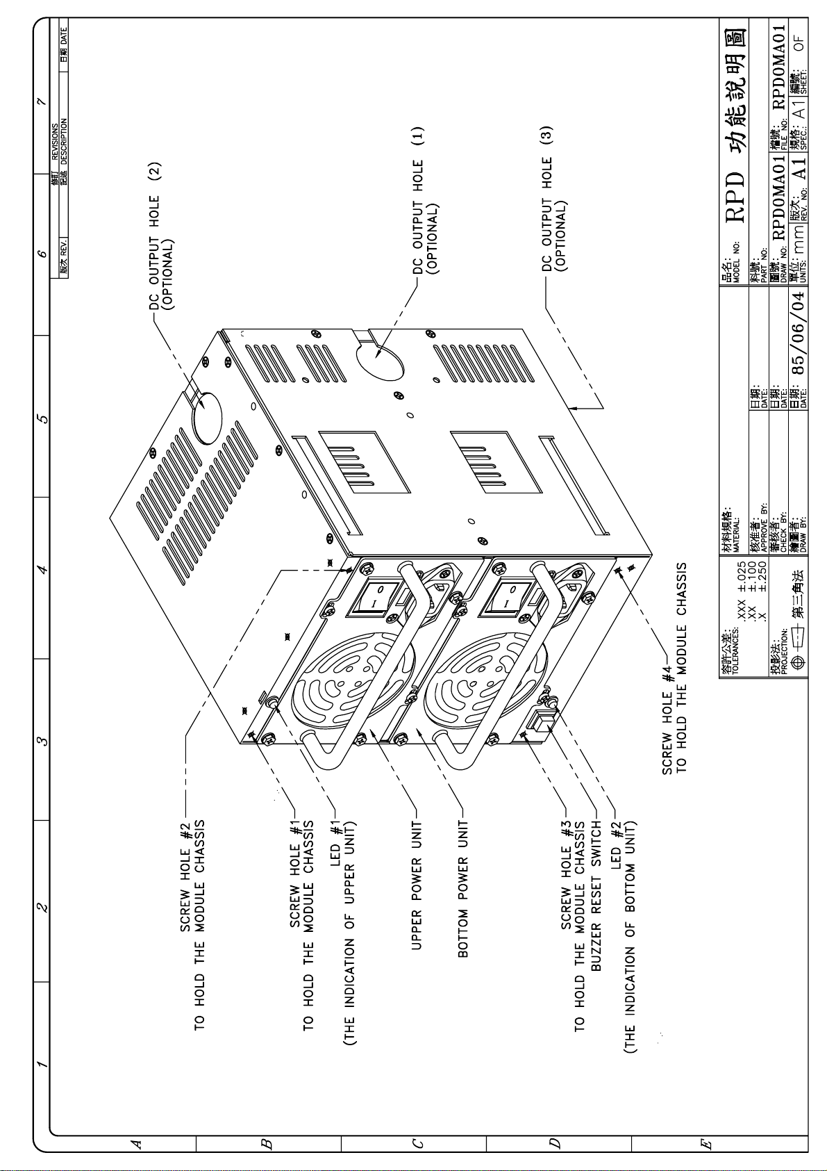
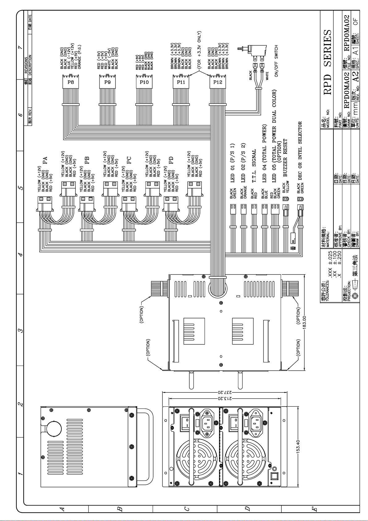
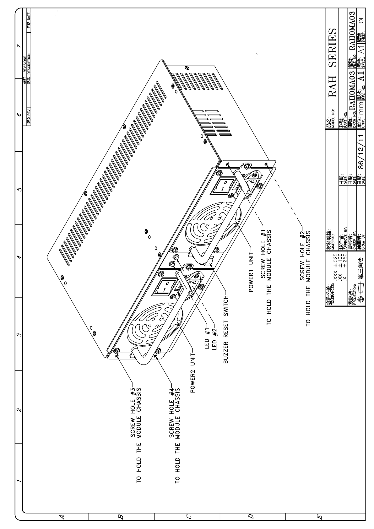
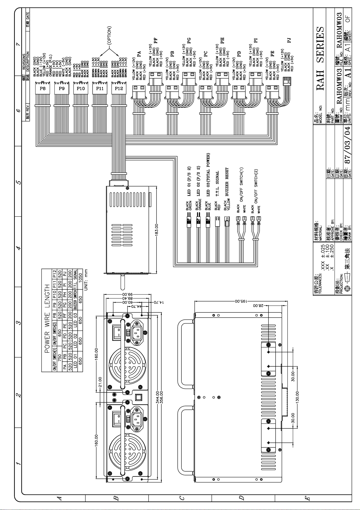
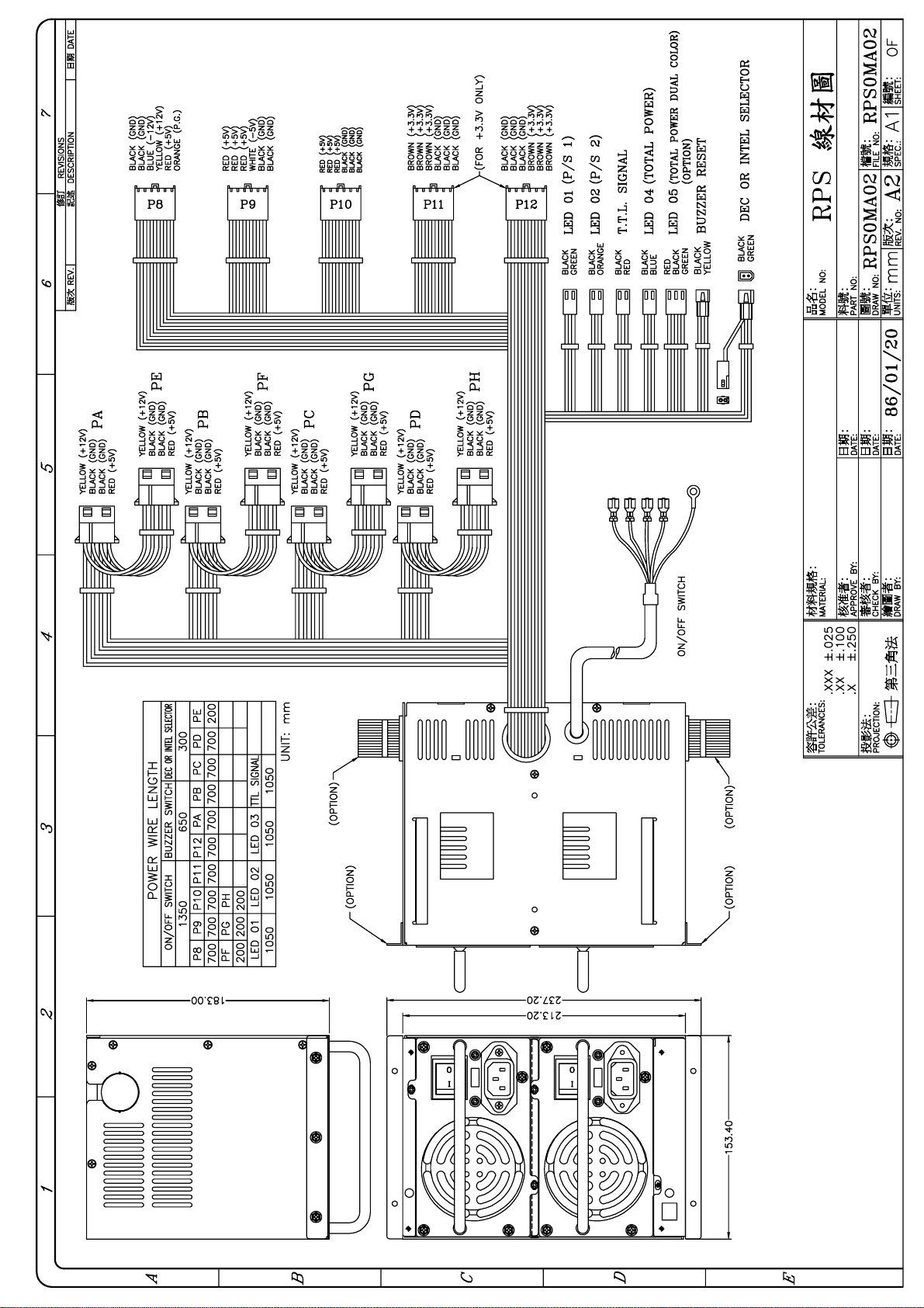
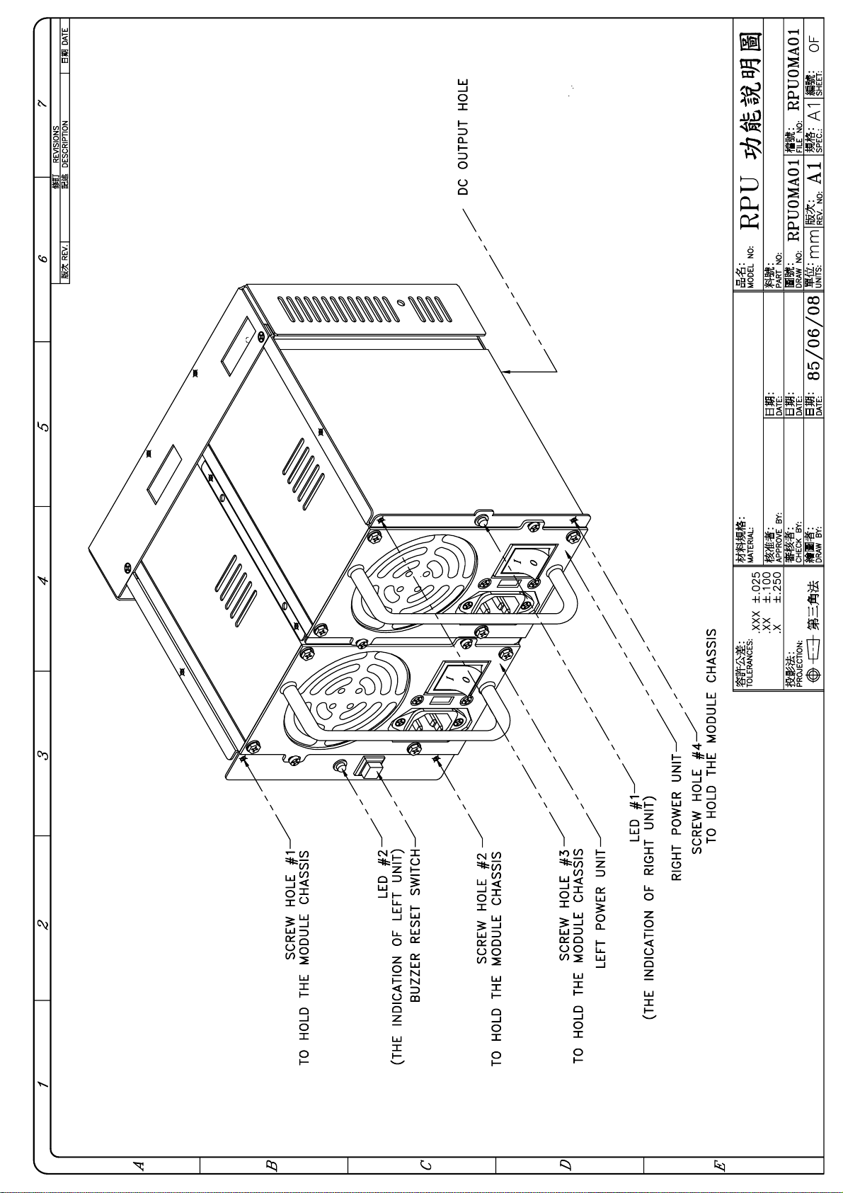
1.3 Drawing page 2~16
1.4 Features page 17
1.5 Specification page 18~21
1.6 Installation & Testing page 22~23
1.7 Hot-Swap Procedures page 24
1.8 DC ON/OFF Switch Installation page 24
1.9 Pinouts and function of connectors page 25
1.10 Trouble shooting page 26
Page 2

1.1 INTRODUCTION
Thank you for the purchase of the Redundant Switching Power System RPX product
( X may stand for A / D / H / I / M / S / U ), each model has the same main structure
and functions. The difference is on the shape and dimension. For each detail drawing,
please refer to the section 1.3.
Your RPX is a redundant switching power supply set, it consists of
(1) complete metal frame (optional)
(2) two PS/2 form factor power supplies with HOT-PLUGGABLE capability
(3) redundant power control board (RPC)
(4) power supply unit holder,
It delivers full safety redundant ( hot-swappable ) function and provides the
hot-pluggable feature. In other words, it can offer a more reliable and safer,
easy install / maintain operation in Power Supply to your computer system.
Its major function is the two power supplies can mutually backup when one of
the power supplies is defective. At the same time, it provides the warning subsystem,
such as LED display, buzzer alarm, power defective signal etc.
When both the power supplies are at normal condition, it balances the load share and
increases the power supply system's reliability.
To really discover the power and ease in using this product, we recommend that you
read through this manual carefully.
1.2 PACKING
Your RPX box package should consist of the followings:
(A) 1 x RPX
(B) 1 x Screws pack
(C) 1 x User's manual
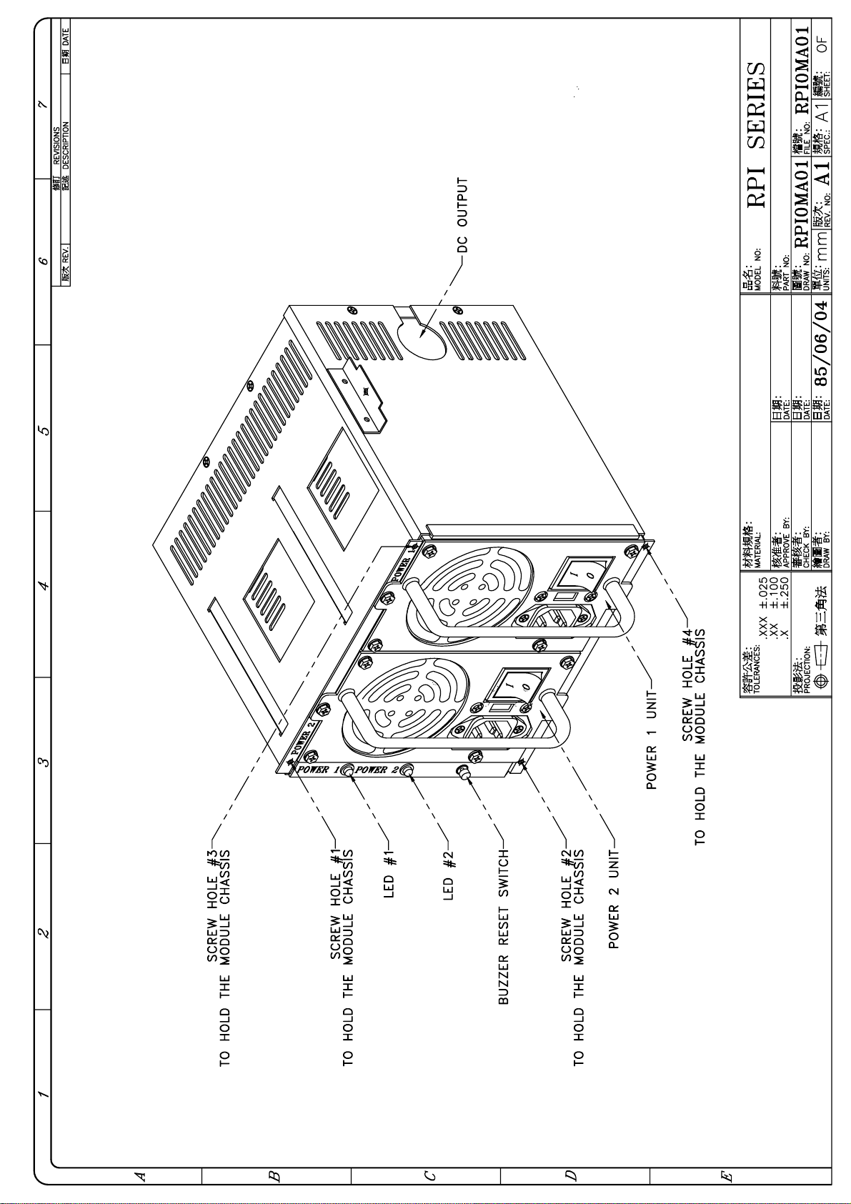
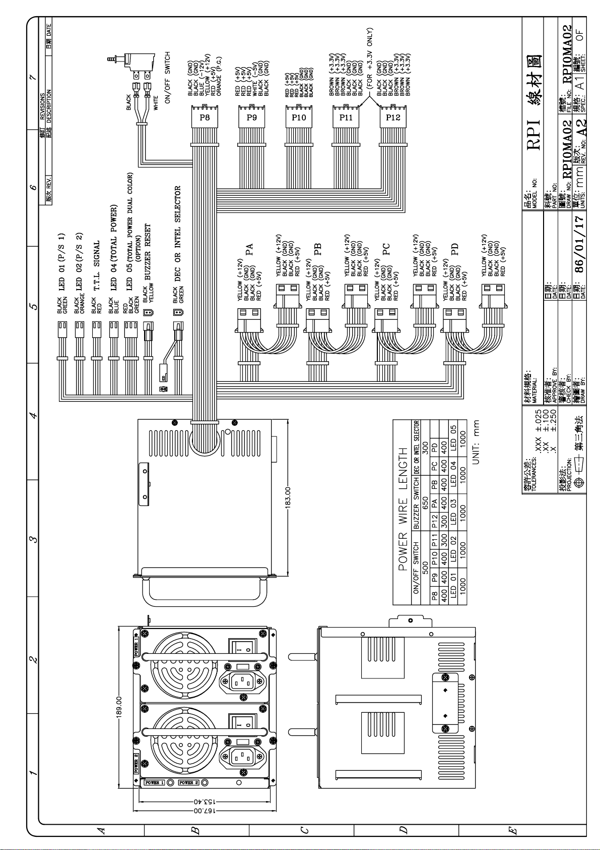
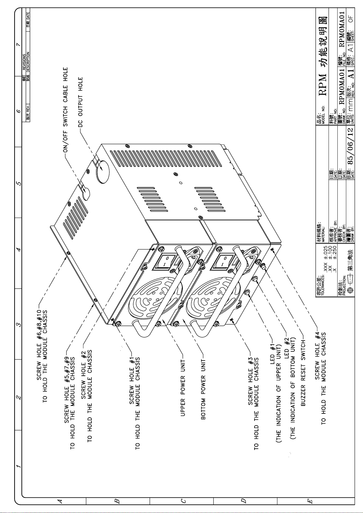
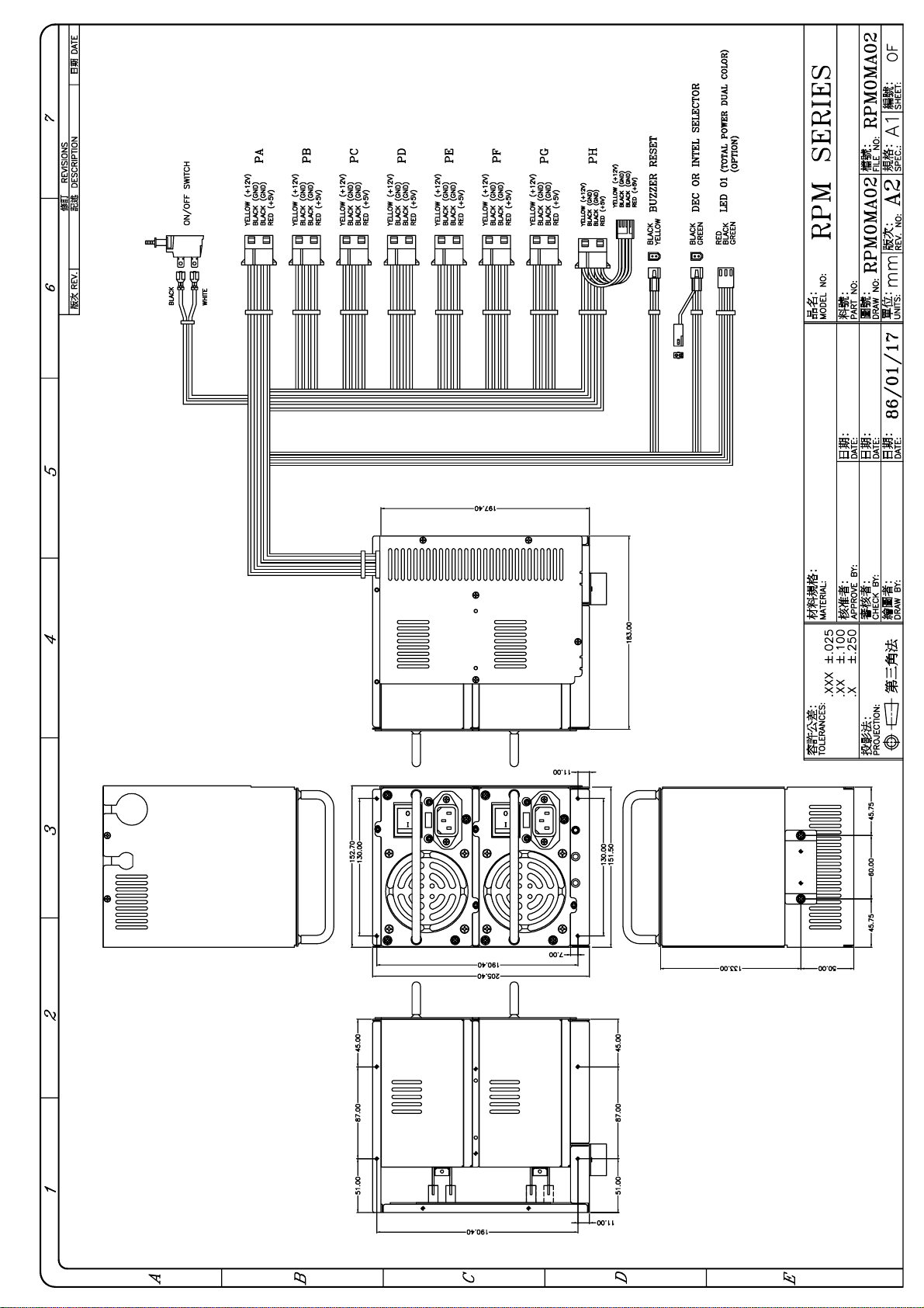
1.3 DRAWING
MODEL NUMBER IDENTIFICATION:
RP X
- X XXX X [ X X X X ]
RP ---- REDUNDANT POWER SUPPLY
FIRST X ---- A / D / H / I / M / S / U ETC.
SECOND X ---- 4 STAND FOR 4 DC OUTPUTS (5 / 12 / -5 / -12V)
5 STAND FOR 5 DC OUTPUTS (5 / 12 / -5 / -12V / 3.3V)
THIRD XXX ---- OUTPUT WATTS (250 / 300 / 400)
FOURTH X ---- F STAND FOR WITH EMI LINE FILTER
BLANK STAND FOR WITHOUT EMI FILTER
6TH X ---- OPTIONAL FUNCTION ( A: AVS; P: PFC )
7TH X ---- R STAND FOR ATX SYSTEM
BLANK STAND FOR NON-ATX SYSTEM
8TH X ---- VERSION
1
Page 3
Page 4
Page 5
Page 6
Page 7
Page 8
Page 9
Page 10
Page 11

Page 12
Page 13
Page 14

Page 15

16
Page 16

1.4 FEATURES
REDUNDANCY
HOT-SWAP
FUNCTION
BUZZER
POWER
DEFECTIVE
SIGNAL
LED'S
HOT-PLUGGABLE
FUNCTION
SAFETY
( CHECK VENDOR )
RELIABILITY
COMPATIBILITY
( RPD ONLY )
Offer redundant function for power system and mutually backs up the
outputs. A zero transfer time when backup takes place.
The power system provides a Hot-Swap function. This means when
either one of the redundant power supplies fails or breaks down, you
can easily replace failed unit without any interference to the system.
A warning buzzer sounds when any one of the power supplies fails. The
warning buzzer is resettable from either the front control panel or the
switch on the rear side.
The unit provides a power defective signal thru the power monitor card
(PMC-21 / 22) to acknowledge the system.
The warning LED‘s can be found either on the rear side or the control
panel of the power system. Tells if one of the two power supplies has
failed, by LED flashing or blinking.
The power system provides a Hot-Pluggable function. This method
allows the power units in the Disk Array / File Server to be removed or
inserted very easily without opening and closing the chassis.
Since the power system used in the Disk Array / File Server is all DC
current ( including the I / O Switch operation, and the power for the
drive ), it prevents a person from being shocked by high AC voltage
during the installation or Hot-Swap procedure.
The power unit‘s ON / OFF switch is controlled by the use of a very
small DC current, this prevents damage the ON / OFF switch, keep the
system from a total uncontrollable situation.
The enclosure of the power system is designed the same as the Big L
form factor power supply, so under proper arrangement of the system
chassis the Big L form factor and the redundant power system can be
compatible.
17
Page 17

1.5 SPECIFICATION
INPUT CHARACTERISTICS: RPX - 4250 / 5250
* VOLTAGE : 90 - 132 VAC OR 180 - 264 VAC SWITCHABLE
* FREQUENCY : 47 - 63 HZ
* INPUT CURRENT : 3.0 A / 1.5 A PER UNIT (PARALLEL)
6.0 A / 3.0 A ( ONE POWER SUPPLY )
* INRUSH CURRENT : 30 A MAX. FOR 115 VAC,
60 A MAX. FOR 230 VAC ( ONE POWER SUPPLY)
OUTPUT CHARACTERISTICS :
OUTPUT CURRENT REGULATION OUTPUT
OUTPUT
VOLTAGE
MIN. (A) MAX. (A) LOAD LINE
7.0 25/50*
5 50 mV + / - 5% + / - 1%
3.0** 10/20**
RIPPLE & NOISE
MAX. (P-P)
12 2.5 14/28* + / - 5% + / - 1% 100 mV
-5V 0 0.5 + / - 10% + / - 2% 150 mV
-12 0 0.5 + / - 10% + / - 2% 150 mV
3.3*** 3 20 + / - 5% + / - 1% 50 mV
* : PEAK FOR 1 MINUTE ** : UNDER WITH 3.3 V OUTPUT CONDITION
*** : 3.3 OUTPUT IS OPTIONAL
THE MAX. TOTAL OUTPUT OF +5V AND +3.3V IS 125W.
°
* TEMPERATURE RANGE : OPERATING 0
* TRANSIENT RESPONSE : OUTPUT VOLTAGE RETURNS IN LESS THAN 1 ms
MAX. FOLLOWING A 50 % LOAD CHANGE
* HOLD UP TIME : 16 ms MINIMUM AT FULL LOAD & NOMINAL INPUT VOLTAGE
* DIELECTRIC WITHSTAND : INPUT TO FRAME GROUND 1500 VAC FOR 1 SEC.
* HUMIDITY : 10 - 90 % RH
* EFFICIENCY : 70 % TYPICAL AT FULL LOAD
* POWER GOOD SIGNAL : ON DELAY 100 ms TO 500 ms, POWER FAIL ≥ 1 ms
* OVERLOAD PROTECTION : 110 - 150 % MAX. ( POWER UNIT )
* OVER VOLTAGE PROTECTION : + 5V OUTPUT: 5.5 V --- 6.5 V
* SHORT PROTECTION
* ALARM METHOD: 1) AUDIO ALARM 2) FAULT LED 3) POWER DEFECTIVE SIGNAL
* EMI NOISE FILTER: AC INPUT LINE FILTER FOR FCC CLASS B ON EACH UNIT
* SAFETY: EACH POWER UNIT ARE UL / CSA / TÜV APPROVAL
* HOT-SWAPPABLE & HOT-PLUGGABLE CAPABILITY
* DIMENSION : REFER THE DRAWING
*REDUNDANCY: BALANCED SHARE LOAD METHOD
C --- 50 °C, STORAGE -20 °C --- 80 °C
18
Page 18

INPUT CHARACTERISTICS: RPX - 4300 / 5300
* VOLTAGE : 90 - 132 VAC OR 180 - 264 VAC SWITCHABLE
* FREQUENCY : 47 - 63 HZ
* INPUT CURRENT : 3.4 A / 1.7 A PER UNIT (PARALLEL)
6.2 A / 3.1 A ( ONE POWER SUPPLY )
* INRUSH CURRENT : 40 A MAX. FOR 115 VAC,
80 A MAX. FOR 230 VAC ( ONE POWER SUPPLY)
OUTPUT CHARACTERISTICS :
OUTPUT CURRENT REGULATION OUTPUT
OUTPUT
VOLTAGE
-5V 0 0.5 + / - 10% + / - 2% 150 mV
MIN. (A) MAX. (A) LOAD LINE
7.0 25/50*
5 50 mV + / - 5% + / - 1%
3.0** 10/20**
12 2.5 14/28* + / - 5% + / - 1% 100 mV
RIPPLE & NOISE
MAX. (P-P)
-12 0 0.5 + / - 10% + / - 2% 150 mV
3.3*** 3 20 + / - 5% + / - 1% 50 mV
* : PEAK FOR 1 MINUTE ** : UNDER WITH 3.3 V OUTPUT CONDITION
*** : 3.3 OUTPUT IS OPTIONAL
THE MAX. TOTAL OUTPUT OF +5V AND +3.3V IS 125W.
°
* TEMPERATURE RANGE : OPERATING 0
* TRANSIENT RESPONSE : OUTPUT VOLTAGE RETURNS IN LESS THAN 1 ms
MAX. FOLLOWING A 50 % LOAD CHANGE
* HOLD UP TIME : 16 ms MINIMUM AT FULL LOAD & NOMINAL INPUT VOLTAGE
* DIELECTRIC WITHSTAND : INPUT TO FRAME GROUND 1500 VAC FOR 1 SEC.
* HUMIDITY : 10 - 90 % RH
* EFFICIENCY : 70 % TYPICAL AT FULL LOAD
* POWER GOOD SIGNAL : ON DELAY 100 ms TO 500 ms, POWER FAIL ≥ 1 ms
* OVERLOAD PROTECTION : 110 - 150 % MAX. ( POWER UNIT )
* OVER VOLTAGE PROTECTION : + 5V OUTPUT: 5.5 V --- 6.5 V
* SHORT PROTECTION
* ALARM METHOD: 1) AUDIO ALARM 2) FAULT LED 3) POWER DEFECTIVE SIGNAL
* EMI NOISE FILTER: AC INPUT LINE FILTER FOR FCC CLASS B ON EACH UNIT
* SAFETY: EACH POWER UNIT ARE UL / CSA / TÜV APPROVAL
* HOT-SWAPPABLE & HOT-PLUGGABLE CAPABILITY
* DIMENSION : REFER THE DRAWING
* REDUNDANCY: BALANCED SHARE LOAD METHOD
C --- 50 °C, STORAGE -20 °C --- 80 °C
19
Page 19

INPUT CHARACTERISTICS: RPX - 4400 / 5400
* VOLTAGE : 95 - 132 VAC OR 190 - 264 VAC SWITCHABLE
* FREQUENCY : 47 - 63 HZ
* INPUT CURRENT : 4.0 A / 2.0 A PER UNIT (PARALLEL)
8.0 A / 4.0 A ( ONE POWER SUPPLY )
* INRUSH CURRENT : 40 A MAX. FOR 115 VAC,
80 A MAX. FOR 230 VAC ( ONE POWER SUPPLY)
OUTPUT CHARACTERISTICS :
OUTPUT CURRENT REGULATION OUTPUT
OUTPUT
VOLTAGE
-5V 0 1 + / - 10% + / - 1% 150 mV
MIN. (A) MAX. (A) LOAD LINE
7.0 36/72*
5 50 mV + / - 3% + / - 1%
3.0** 20/40**
12 2.5 24/48* + / - 3% + / - 1% 100 mV
RIPPLE & NOISE
MAX. (P-P)
-12 0 1 + / - 10% + / - 1% 150 mV
3.3*** 3 20 + / - 3% + / - 1% 50 mV
* : PEAK FOR 1 MINUTE ** : UNDER WITH 3.3 V OUTPUT CONDITION
*** : 3.3 OUTPUT IS OPTIONAL
ACTUAL POWER USAGE SHALL NOT OVER THE TOTAL OUTPUT POWER
THE MAX. TOTAL OUTPUT OF +5V AND +3.3V IS 160W.
°
* TEMPERATURE RANGE : OPERATING 0
* TRANSIENT RESPONSE : OUTPUT VOLTAGE RETURNS IN LESS THAN 1 ms
MAX. FOLLOWING A 50 % LOAD CHANGE
* HOLD UP TIME : 16 ms MINIMUM AT FULL LOAD & NOMINAL INPUT VOLTAGE
* DIELECTRIC WITHSTAND : INPUT TO FRAME GROUND 1500 VAC FOR 1 SEC.
* HUMIDITY : 10 - 90 % RH
* EFFICIENCY : 70 % TYPICAL AT FULL LOAD
* POWER GOOD SIGNAL : ON DELAY 100 ms TO 500 ms, POWER FAIL ≥ 1 ms
* OVERLOAD PROTECTION : 110 - 150 % MAX. ( POWER UNIT )
* OVER VOLTAGE PROTECTION : + 5V OUTPUT: 5.5 V --- 6.5 V
+ 12V OUTPUT: 13.5 V --- 15.5 V ( OPTIONAL )
* SHORT PROTECTION
* ALARM METHOD: 1) AUDIO ALARM 2) FAULT LED 3) POWER DEFECTIVE SIGNAL
* EMI NOISE FILTER: AC INPUT LINE FILTER FOR FCC CLASS B ON EACH UNIT
* SAFETY: EACH POWER UNIT ARE UL / CSA / TÜV APPROVAL
* HOT-SWAPPABLE & HOT-PLUGGABLE CAPABILITY
* DIMENSION : REFER THE DRAWING
* REDUNDANCY: BALANCED SHARE LOAD METHOD
C --- 50 °C, STORAGE -20 °C --- 80 °C
20
Page 20

INPUT CHARACTERISTICS: RPX-5300F / 5400F-RV
VOLTAGE: 90 - 132 VAC / 180 - 260 VAC SWITCHABLE
FREQUENCY: 47 - 63 Hz
INPUT CURRENT: 3.0A / 1.5A PER UNIT (PARALLEL), 6.0A / 3.0A (ONE POWER)
INRUSH CURRENT: 40A MAX. FOR 110 VAC, 80A MAX. FOR 220VAC
OUTPUT CHARACTERISTICS:
OUTPUT
VOLTAGE
+5V 7.0 30/50*
-5V 0 0.5/1.0* -10%~+14%
+12V 2.5 11
-12V 0 0.5/1.0* -10%~+15%
+3.3V 1.0 25/18*
OUTPUT CURRENT REGULATIO N OUTPUT
RIPPLE & NOISE
MIN. [A] MAX. [A] LOAD LINE
±
±
±
5%
6%
5%
±
±
±
±
±
1%
1%
1%
1%
1%
MAX. [P-P]
50mV
150mV
100mV
150mV
50mV
+5VSB 0 800mA
±
5%
±
1%
50mV
N / N: 300 / 400W
300W VERSION: +5V AND +3.3V TOTAL OUTPUT MAX: 150W
400W VERSION: +5V AND +3.3V TOTAL OUTPUT MAX: 250W
SPECIFICATION:
TEMPERATURE RANGE: OPERATING 0℃ -- 50℃; STORAGE -20℃ -- 80℃
TRANSIENT RESPONSE: OUTPUT VOLTAGE RETURNS IN LESS THAN 1 ms MAX.
FOLLOWING A 50% LOAD CHANGE
HOLD UP TIME: 16 ms MINIMUM AT FULL LOAD & NORMAL INPUT VOLTAGE
DIELECTRIC WITHSTAND: INPUT / OUTPUT 1500 VAC FOR 1 SECOND
INPUT TO FRAME GROUND 1500 VAC FOR 1 SECOND
HUMIDITY: 10 ~ 90% RH
EFFICIENCY: 60% TYPICAL, AT FULL LOAD
POWER GOOD SIGNAL: ON DELAY 100 ms TO 500 ms, OFF DELAY 1 ms
OVER LOAD PROTECTION: 130 ~ 150% MAX.
OVER VOLTAGE PROTECTION: +5V 5.5V ~ 7.0V, 3.3V: 3.8V ~ 4.5V
OVER CURRENT PROTECTION: SHORT CIRCUIT
ALARM METHOD: 1. AUDIO ALARM, 2. FAULT LED, 3. POWER DEFECTIVE SIGNAL
EMI NOISE FILTER: AC INPUT LINE FILTER FOR FCC CLASS B ON EACH POWRE
UNIT ARE AVAILABLE UPON ORDER
SAFETY: UL / CSA / TÜV APPROVAL
HOT-SWAPPABLE / HOT-PLUGGABLE CAPABILITY
DIMENSION: REFER TO THE DRAWING
REDUNDANCY: BALANCE SHARE LOAD METHOD
REMOTE ON/OFF: OPERATE BY A REMOTE (SELV) SIGNAL
5VSB STANDBY VOLTAGE: A LOW CURRENT CONTINUOUS 100mA SOURCE
AT +5V, ALWAYS ENABLE, CAN NOT BE SWITCHED OFF
*
21
Page 21

1.6 INSTALLATION & TESTING
Turn off the main on/off switch and the individual power supply's on/off switches ( on
the rear side ).
Mount the power supply in the case using the mounting hardware that is included, the
mounting holes in the power supply should match up with those in the case.
Attach the six-pin connectors ( 20-pin connector for ATX system ) to the motherboard by
following the motherboard instructions, there are different kinds of pinouts in both the power
supply and motherboard, they should match each other,
undetectable harmness.
otherwise the connection will cause
Attach all the remaining power supply connections to the various peripherals as needed,
these connectors are "keyed", so there will be only one possible way to connect them.
NOTE: The power unit is designed for AT system or ATX system. Before using the power unit,
please aware the following instruction; otherwise, the power supply may not work
properly.
There is a wire lead accompany with the DC wires.
1. If the power unit is for AT system, please connect the connector.
2. If the power unit is for ATX system, then please do
connector. Just leave it alone.
Soft Power Function:
If you are going to use soft power function, the power has to be always wired ON. You may
either keep the power switch turned on, refer to figure A (Note: The power supply’s main on / off
control is designed by using DC current. Please ensure to connect the two wires to the same
vertical side), or just to figure B. Then the power supply can be turned on by the screw-on
connector, refer to figure B. Then the power supply can be turned on by the soft power function
of the motherboard only
.
not connect the
22
Page 22

IMPORTANT:
If you try to convert the power supply from for ATX system use to for normal AT
system use, please refer the following steps:
1. Source the wires converter (20 pins connector
6 pins connectors P8, P9, P11, P12).
P8, P9 for normal AT motherboard
P11, P12 for 3.3V DC output
Convert the 20 pins connector to 6 pins connector.
2. The selector for DEC ALPHA system & INTEL system should be selected as DEC ALPHA
system. (Please refer the instruction sheet.)
3. If you
short the white and black wires (for DC on / off switch operation use) for ATX
system by using the screw-on connector, then please recover back to original design. The
on / off switch operation is controlled by the on / off switch.
Before applying power to the system, make sure there are no loose or incorrect
connections. The input voltage has been set to the
correct voltage ( 110 / 220 V, the voltage
selector are on the rear side ), double check that all connection to the motherboard are properly
matched.
Maybe you would like to test the redundancy function before you put back the cover
of your system chassis. Turn on the main on/off switch ( if your power supply‘s main on/off wire
lead is black and white color, which means the power supply on / off control is design by using
the DC current, please refer to Sec. 1.8 for installing guide), and the individual power supply's
on/off switches ( on the rear side ), you will notice that if the power unit is operating properly,
then individual LEDs , external warning LEDs ( Please refer to Sec. 1.9 for detail explanation )
are lit GREEN, now turn off one of the power supplies' on/off switch, the Warning Buzzer in the
power system will sound, and the external warning LED which displays the status of the total
power supply system will change color to be RED (
design, some of those models LED has flashing design
Please note, not every model has this
), the individual LEDs ( both on the
rear side or on the front control panel ) indicating the power supply's status will not light.
Meanwhile the power system will continue to backup the power output without affecting the
computer system's operation.
The Warning Buzzer will continue sounding, the user can reset the Warning Buzzer by pressing
the buzzer reset switch at the rear side, refer to the drawing on Sec. 1.3, or use the reset switch
which can be found on the front control panel of the system chassis, the reset switch can be
connected by wires lead provided from the power supply system (Please refer to Sec. 1.9).
Turn on the power supply which is turned off for testing earlier, the sound of the Warning
Buzzer will disappear, the external warning LED will turn GREEN again ( or
not flashing ), the
LED indicating the status of the power supply will light again, test another power supply by
performing the similar procedure.
If you use the power defective signal, there is a two pins connector ( refer to the drawing on Sec.
1.3 and table on Sec. 1.9 ), it should be connected to the PMC card properly, please refer the
PMC User's Manual.
If everything works out fine, then turn off the power supplies and the main on / off switch, now
put back the cover of the case and tighten them with the screws which you have retained earlier.
Now you have completed the installation of the RP
X redundant power supply system.
23
Page 23

1.7 HOT-SWAP PROCEDURES
Please refer to the followings when either one power supply unit is found defective.
A) Locate the defective power supply by examining the individual LED or the LED on the front
control panel . (If LED is without light, it indicates the power unit is defective.)
WARNING:
PLEASE PERFORM THE ABOVE STEP CAREFULLY OTHERWISE IT MAY CAUSE
SHUT DOWN OF THE WHOLE SYSTEM.
B) Turn off the individual on / off switch on the rear side.
C) Unplug the power cord which belongs to the defective power supply unit from the AC inlet.
D) Unscrew the screws which fix the defective power supply unit.
E) Remove the defective power supply unit by pulling out method.
F) Replace a new
power supply into the power supply system chassis.
Plug the power cord which is unplugged earlier.
G)
H) Turn on the new power supply unit.
I) Check the LEDs which indicate the total power system status, that SHOULD be from
FLASHING to light GREEN or from RED to GREEN. IF IT SHOWS ANOTHER TYPE,
PLEASE CHECK WITH YOUR VENDOR.
J) Fix the new power supply unit by screwing the screws.
K) If you want to test the NEW one power supply unit in simulating defective situation, please
refer to the Section 1.6 INSTALLATION & TESTING Section.
GOOD power supply unit, set the proper AC input voltage, insert the
1.8 DC ON / OFF SWITCH INSTALLATION
If you notice that there are thin black and white DC wires which connects the RPX system and
the ON / OFF switch, generally, the ON / OFF switch consists of four pins on it, and splits into
two half ( left / right ), connect the two thin wires from the power supply system to the same side
either left or right side, DO NOT cross connect, since there is no particular pin assignments to
the ON / OFF switch the two thin DC wires can be connected either ways on the same side of
the ON / OFF switch. If there are two pairs of thin black and white DC wires, please use one
pair ( one black wire, one white wire ) DC wires connected to one side, another pair DC wires to
the other side.
The specification of the DC ON / OFF controller is :
WORKING VOLTAGE
220 VAC ===> 5 VDC 20mA
: 110 VAC ===> 5 VDC 20mA
24
Page 24
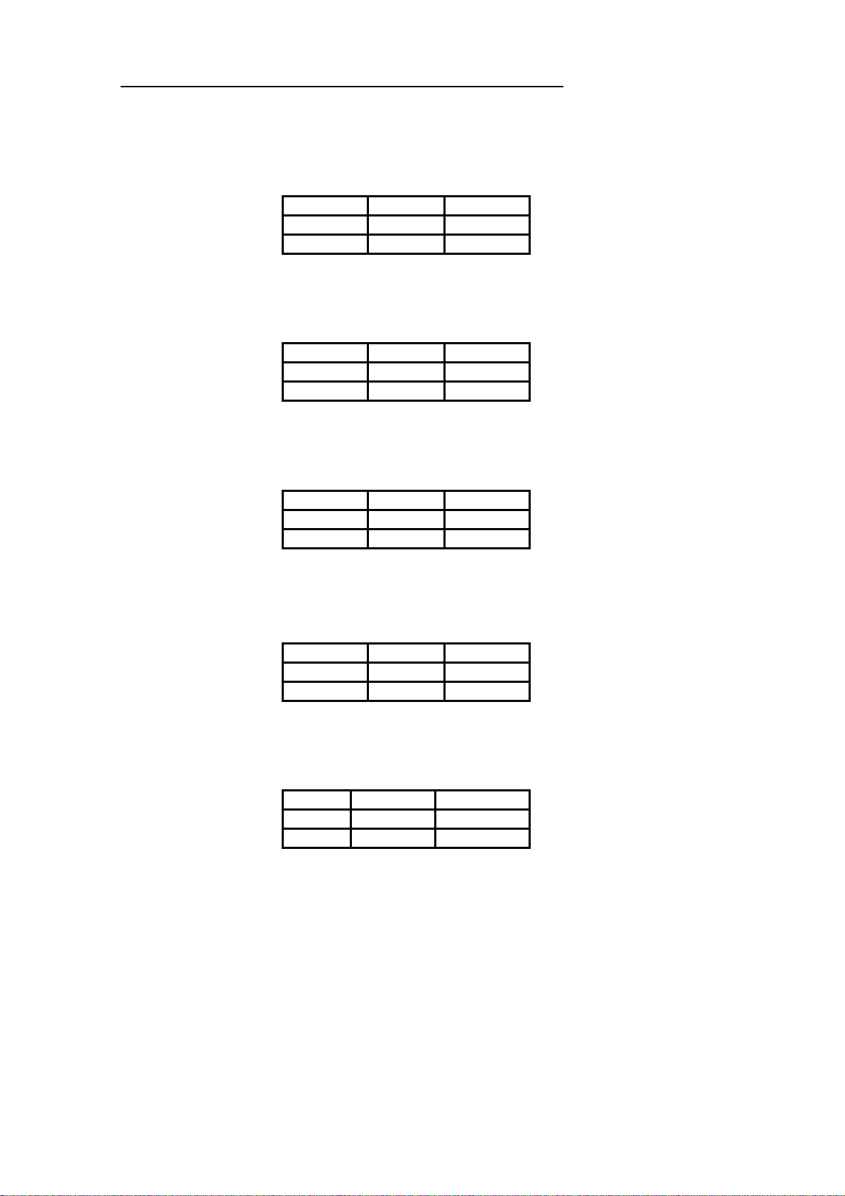
1.9 PINOUTS AND FUNCTION OF THE CONNECTORS
*** PLEASE AWARE THE POLARITY
THE LED CONNECTOR OF POWER #1
PIN# COLOR VOLTAGE
1 GREEN +5V
2 BLACK GND
THE LED CONNECTOR OF POWER #2
PIN# COLOR VOLTAGE
1 ORANGE +5V
2 BLACK GND
THE LED CONNECTOR OF TOTAL POWER SYSTEM
PIN# COLOR VOLTAGE
1 BLUE +5V
2 BLACK GND
THE BUZZER RESET SWITCH CONNECTOR
PIN# COLOR VOLTAGE
1 YELLOW +12V
2 BLACK GND
THE SIGNAL CONNECTOR OF POWER DEFECT
PIN# COLOR VOLTAGE
1 RED TTL SIGNAL
2 BLACK GND
25
Page 25

1.10 TROUBLE SHOOTING
If you have followed these directions correctly, there should be no problem. Some common
symptoms are : the computer is dead, a "ticking" or "hissing" sound will be heard.
1. Check all the connections.
2. Make sure the system unit is plugged in.
3. Check for short-circuits or defective peripherals by unhooking each peripheral, once at a
time. When the systems functions again, you have solved the problem.
4. Once you hear the buzzer sound or see the LED with RED light ( or the LED is flashing ),
please be aware of:
a. IF the individual ON / OFF is
b. IF the load is over the
c. IF AC input voltage been set correct?
d. IF each power cord been well plugged into the inlet?
ON state?
minimum load ( please refer the SEC. 1.5 specification )?
Suppose the above condition been happened, please wait for 10 - 20 seconds
for releasing the protection state, then test it again.
IF buzzer still sound or the LED shows power unit defective, please locating which power
supply unit is defective by examining which LED is OFF, perform hot-swap procedure at
your proper time, by turning off the on / off switch, unplug the power cord of the defective
one, replace it with a new power supply unit, ( please set the on / off switch of the new
power supply unit to OFF first, after the unit being fixing properly, plug the power cord, turn
on the on / off switch, for the detail description, please refer to the HOT-SWAP
PROCEDURES), send the defective power supply unit to your vendor for RMA operation.
The description stated herein is subject to change without prior notice.
All brand names and trademarks are the property of their respective
owners.
26
Page 26

The “RELIABILITY “ solution to E-application
新巨企業股份有限公司
ZIPPY TECHNOLOGY CORP.
POWER DIVISION
HEADQUARTERS
10F, NO. 50, MIN CHYUAN RD., SHIN-TIEN CITY,
TAIPEI HSIEN, TAIWAN, R.O.C.
TEL: 886-2-29188512 FAX: 886-2-29134969
WEB SITE: http://www.zippy.com.tw E-mail:power@zippy.com.tw
USA OFFICE
U.S. East (Atlantic)
11 Melanie Lane, Unit 1B East Hanover, NJ 07936
TEL:1-973-463-9499 FAX:1-973-453-8014
E-mail:edward@zippy.com
U.S. W est (Pacific)
961 CALLE NEGOCIO, SAN CLEMENTE CA 92673, USA
TEL: 1-949 366 9525 FAX: 1- 949 366 9526
EMAIL: powerusa@zippy.com
CANADA OFFICE
ZIPPY TECHNOLOGY CANADA INC.
Unit3-3671 Viking Way Richmond, B.C V6V 2J5 Canada
TEL:1-604-278-6615 FAX:1-604-278-6624
CELL: 1-778-288-9622 E-mail:ian@zippy.com
Note:
*The description stated here in is subject to change without prior notice.
*All brand names and trademarks are the property of their respective owners
 Loading...