

Page 1

__________________________________________
SERIES
USER'S MANUAL
ZIPPY TECHNOLOGY CORP.
[ POWER DIVISION ]
This document is the property of zippy technology corp. and shall not be copied or used
as the basis for the manufacturing or sell of equipment or devices without permission. Model : RHX series
RHX
Redundant Switching
User's manual
Power System
Page 2

User's manual
Index
1.1 INTRODUCTION ………………………………… 3
1.2 PACKING …………………………………………. 4
1. 3 DRAWING………………………………………… 4-5
1.4 FEATURES ………………………………………… 6-9
1.5 SPECIFICATION ………………………………….10-17
1.6 INSTALLATION AND TESTING ………………..18-19
1.7 HOT-SWAP PROCEDURE ………………………20
1.8 DC ON / OFF SWITCH INSTALLATION ………..21
1.9 PINOUTS & FUNCTION OF CONNECTORS …..22
1.10 TROUBLE SHOOTING …………………………….23
2
Page 3

1. INTRODUCTION
Thank you for your interest in our nice product, the Redundant Switching Power System in
different model (suffixed by character D / H / I individually ) but of the same major structure and
functions. As for the form factor shall be identical with our earlier model RPD,RAH,RPI.
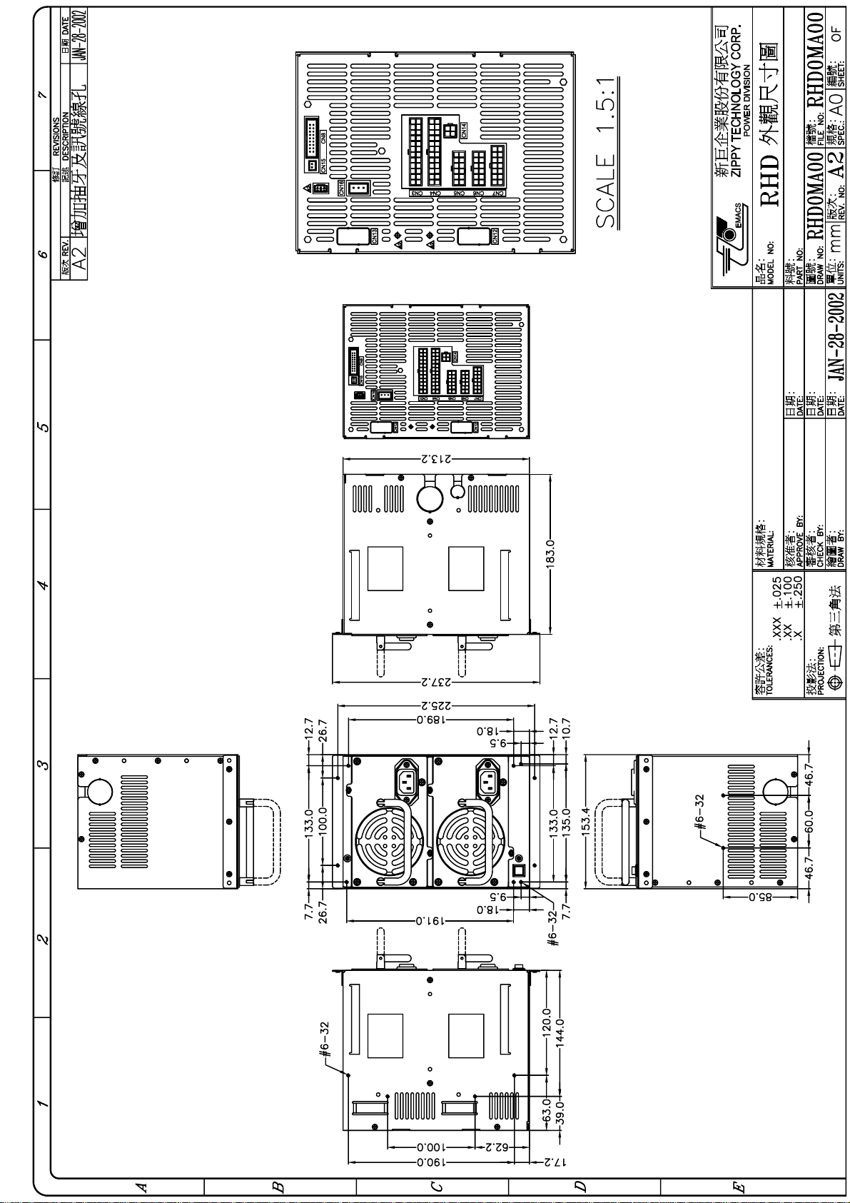
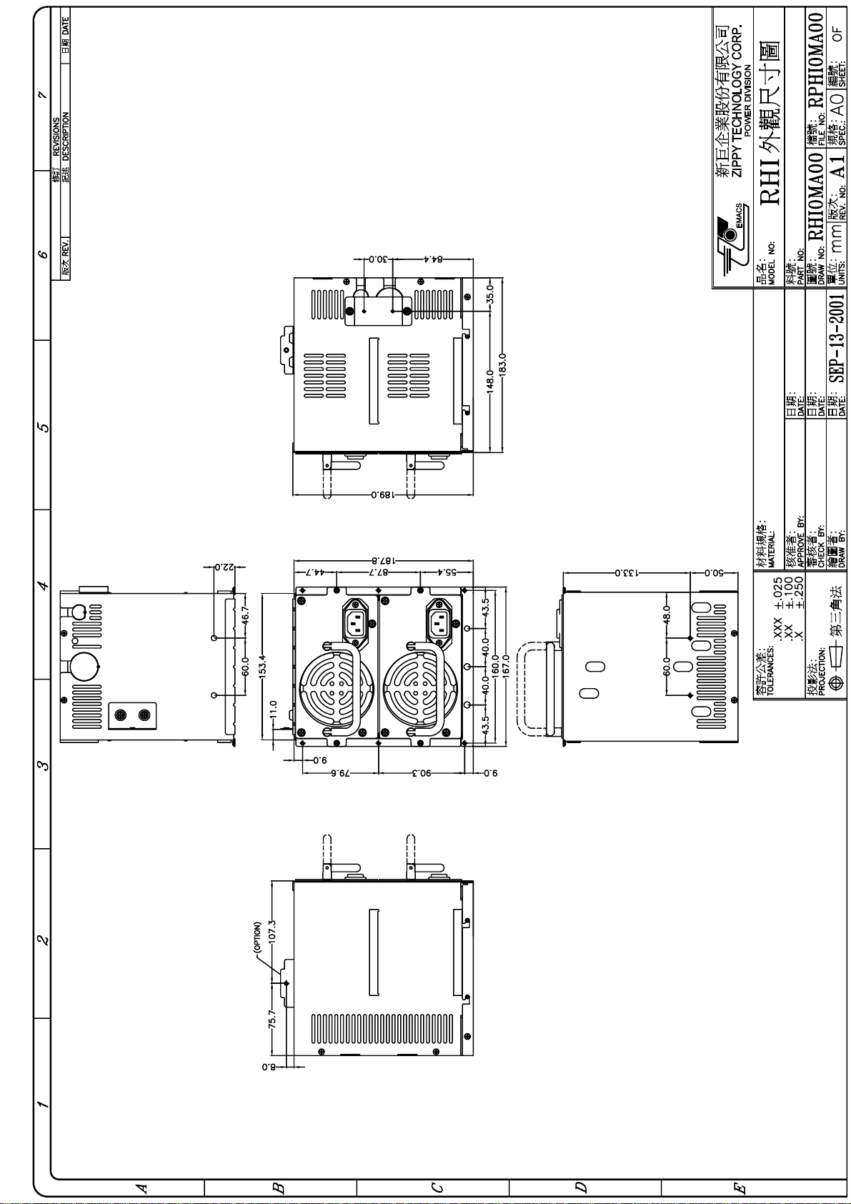
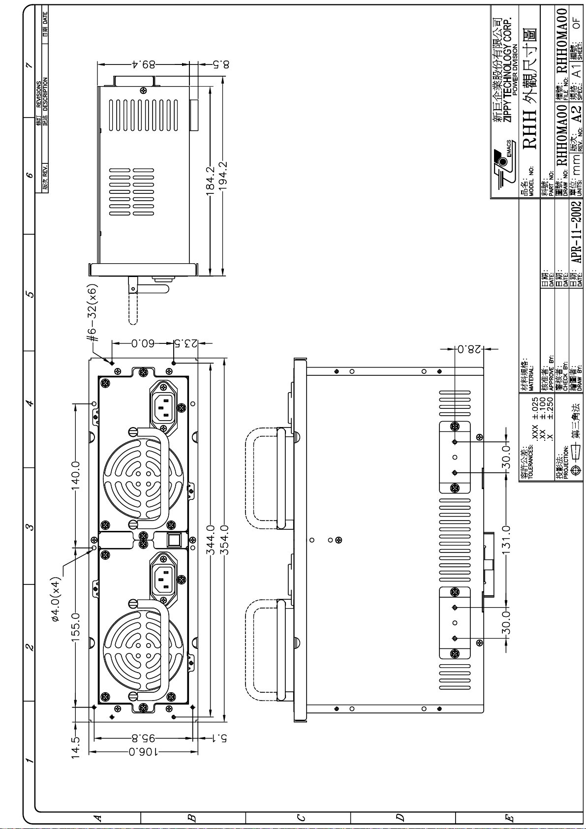
Please refer to drawings in Section 1.3.for the housing and dimension in different models..
Model RHX, a redundant switching power supply system, consists of:
(1) Complete metallic frame (optional)
(2) Two sets of PS/2 power supplies with HOT-PLUGGABLE capability
(3) Redundant power control board
(4) Power supply unit housing,
(5) A set of wire harness (according to customer's choice for different motherboard requirements)
Model RHX is of the hot-plug-in capability and full safety redundant ( hot-swappable) function
with easy installation / operation / maintenance and more reliable Power Supply system
to your computer system than ever you could have.
Two identical power modules are used in one system to backup each other if any one of them
becoming defective and the audio and visual warning signals, such as LED display, buzzer
alarm, power defective signal, etc are initiated simultaneously.
One additional set of AC inlet is to provide users capable of using two different power sources for
each module and sharing the risk of any AC power sources failure.
For the purpose of remote false detection, the warning signals such as: AC input false
detection for each module are provided herein. Signals to be generated in case of abnormal
AC input power module.
Power module - available detection: power module available signals output as soon as the
power module is plug-in seat..
Power Good signal: Power Good Signal output for modules normal voltage outputs only.
Load share should be balanced when these two modules are both in normal operating condition,
The reliability of power supply system can be therefore greatly increased.
Please read this manual carefully so you can operate the power system with a
master hand.
3
Page 4

1.2 PACKING
The contents of a RHX box package shall be at least consisted of the following format :
(A) 1 x RHX
(B) 1 x Screws pack
(C) 1 x User's manual
(D) Output wire (1 set)
1.3 DRAWING
MODEL NUMBER IDENTIFICATION:
RH X - X XXX X [ X X ]
RH ---- REDUNDANT POWER SUPPLY
FIRST X ---- D / H or I ETC.
SECOND X ---- 4 STAND FOR 4 DC OUTPUTS (5 / 12 / -5 / -12V)
6 STAND FOR 6 DC OUTPUTS (5 / 12 / -5 / -12V / 3.3V / +5vsb)
THIRD XXX ---- OUTPUT WATTS (400 / 460)
FOURTH X ---- P STAND FOR WITH ACTIVE POWER FACTOR CORRECTION
4
Page 5
Page 6
Page 7
Page 8

1.4 FEATURES
REDUNDANCY
HOT-SWAP
FUNCTION
BUZZER
POWER
DEFECTIVE
SIGNAL
LED'S
AC IN
DETECTION
(AC/PS1, 2) FOR
EACH POWER
MODULE
Redundant function of the power system will take place in a zero
transfer time and back up the module output for each other,
The power system provides a Hot-Swap function. You can easily
replace the defective unit without any interference to the system
when either one of the redundant power supply module fails or
breaks down
A buzzer alarm will sound up whenever one of the power supply
units fails. The alarm can be reset by a reset switch either located
on the front control panel or from the rear of units. Remote control
function is also available.
The power supply system provides a power defective signal through
a power monitor card (PMC-21 / 22) to acknowledge the system.
The 2 green LED lights (on/off) either on the control panel or from
the rear of the power system indicate if any one of the two power
modules is failed.
This signal output is a " LOW" level, at normal AC input for each
power module.
(It's not provided for RHH series)
EACH POWER
MODULE IS IN
(PD1, 2)
POWER GOOD
(PG1, 2) SIGNAL
FOR EACH
MODULE
DUAL OVP
As the power module is plugged - in, we have a "LOW" level signal
output.
(It's not provided for RHH series)
As normal voltages output from the power module, we have a
"LOW" level signal output.
OVER VOLTAGE PROTECTION circuit is available basically in
each module, now one more OVP circuit after the ORING DIODE
is provided additionally, they are used to protect unit failure due to
any mistakes in connection at terminal blocks by user.
8
Page 9

REMOTE SENSE
for OUTPUT
VOLTAGE
+5V,+3.3V
NON DISTINCTION
OCP
To compensate the voltage outputs drop caused by the copper loss in
longer cable run, two sets of VOLATGE REMOTE SENSE
(+5V,+3.3V) are provided in RHX series.
The OCP designs are identical in either one of power module or both
of two modules of the RHX series power supply system.
+12 V BUILT-IN
SMART
REGULATOR
SOFT SWITCH
HOT - PLUG - in
FUNCTION
SAFETY
( CHECK
VENDOR )
AC INPUT FULL
RANGE
ACTIVE POWER
FACTOR
CORRECTOR
ELECTRO-MAG
NETIC
INTERFERENCE
COMPATIBILITY
(RHD only)
A high efficiency, linear smart regulator is built in for each +12V
output.
A 2.54 pitch and 3 pin connector is provided to match the control
switch which endures extremely small current (Including two
different mode of operation: One Remote On / Off Disable mode and
another always On mode). Please refer to Section 1.8 "Soft Switch
On / Off installation" for more details.
A Hot-Plug-in function is provided in this system, It allows the
power supply units in either Disk Array or File Servers to be
removed or inserted with ease without opening and closing from
chassis.
Since the power supply unit in Disk Array / File Server are all of
DC , ( Including power for I / O Switch , and some other drives ), it
prevents a person from being shocked down by high AC voltage
during any installation or Hot-Swap procedure.
No worry about failure of power supply unit because of your
different power sources. Full range of input voltage for each RHX
POWER MODULE is available covering from 90V to 264V single
phase AC voltage..
Active POWER FACTOR CORRECTOR in RHX design is useful
to reduce more than 63% of input RMS current better than any
conventional power supply unit, and to upgrade the power source
utilization, which is recognized by the EN61000-3-2 regulation.
Our Built - in EMI suppression circuit to eliminate any electro magnetic interference are fully complying with CISPR 22
(EN 55022) ,及 FCC code.
The enclosure of RHD power supply system is designed identical to
the Big L form factor power supply, so that the Big L form factor
and the redundant power system can be compatible under the
proper arrangement.
9
Page 10

1.5 SPECIFICATIONS
PRODUCT SPECIFICATIONS
MODEL:RHD/H/I-4400P
400 WATT HIGH PERFORMANCE POWER SUPPLY with ACTIVE POWER FACTOR
CORRECTION
A、INPUT CHARACTERISTICS:
1、VOLTAGE: FULL RANGE, SINGLE PHASE, 90∼264VAC
2、FREQUENCY: 47∼63HZ
3、INPUT CURRENT: 2.5A(RMS)FOR 230VAC
7A(RMS)FOR 115VAC
4、INRUSH CURRENT: 65A MAX. FOR 115 VAC PER MODULE
125A MAX. FOR 230 VAC PER MODULE
B、OUTPUT CHARACTERISTICS:
OUTPUT OUTPUT CURRENT OUTPUT VOLTAGE REGULATION OUTPUT RIPPLE
& NOISE (p-p)
VOLTAGE MIN. MAX. RANGE MIN NOM MAX MAX.
+5V 5.0A 35 A
-5V 0A 0.8A
+12V 2.5A 20A
-12V 0A 1A
±5%
±5%
±5%
±5%
+4.75 +5.00 +5.25 60mV
-4.75 -5.00 -5.25 100mV
+11.40 +12.00 +12.60 100mV
-11.40 -12.00 -12.60 100mV
TOTAL POWER: 400W (MAX.)
NOISE BANDWIDTH : DC TO 20MHZ.
C、SPECIFICATION
TEMPERATURE RANGE: OPERATING 0℃∼40℃,STORAGE -20℃∼80℃
HOLD UP TIME: 16ms MIN.
DIELECTRIC WITHSTAND: INPUT/OUTPUT 1500 VAC FOR 1 minute
INPUT TO FRAME GROUND 1500 VAC FOR 1 minute
HUMIDITY: 10∼90%RH
EFFICIENCY: 70% TYPICAL AT 115V,AT FULL LOAD
POWER GOOD SIGNAL: ON DELAY 100ms TO 500ms,OFF DELAY 1ms
OVER LOAD PROTECTION: 110∼150% MAX
OVER CURRENT PROTECTION : +5V→44A∼60A,+12V→29.1A∼40.5A
OVER VOLTAGE PROTECTION:+5V→5.7V∼6.5V,+12V→13.6V∼15V
EMI: FCC CLASS B , CISPR 22 CLASS B
SAFETY: EACH POWER UNIT SHALL BE FULLY COMPLYING
WITH THE UL / CSA / TÜV APPROVAL
ALARM METHOD: 1) AUDIO ALARM 2) FAULT LED INDICATOR
3) POWER DEFECTIVE SIGNAL.
HOT- SWAPPABLE AND HOT- PLUG - IN CAPABILITY
MEET IEC-1000-3-2 CLASS D (ACTIVE PFC)
DIMENSION: 213mm*183mm*154mm (D*W*H)
10
Page 11

PRODUCT SPECIFICATIONS
MODEL:RHD/H/I-4460P
460WATT HIGH PERFORMANCE REDUNDANT
POWER SUPPLY (ACTIVE POWER FACTOR CORRECTION)
A、INPUT CHARACTERISTICS:
1、VOLTAGE: FULL RANGE,SINGLE PHASE, 90∼264VAC
2、FREQUENCY: 47∼63HZ
3、INPUT CURRENT: 4A (RMS)FOR 230VAC
8A (RMS)FOR 115VAC
4、INRUSH CURRENT: 65A MAX. FOR 115 VAC PER MODULE
125A MAX. FOR 230 VAC PER MODULE
B、OUTPUT CHARACTERISTICS:
OUTPUT OUTPUT CURRENT OUTPUT VOLTAGE REGULATION OUTPUT RIPPLE
AND NOISE (p-p)
VOLTAGE MIN. MAX. RANGE MIN NOM MAX MAX.
+5V 5.0A 40 A
-5V 0A 0.8A
+12V 2.5A 27A
-12V 0A 1A
±5%
±5%
±5%
±5%
+4.75 +5.00 +5.25 60mV
-4.75 -5.00 -5.25 100mV
+11.40 +12.00 +12.60 100mV
-11.4 -12.00 -12.60 100mV
TOTAL POWER: 460W (MAX.)
NOISE BANDWIDTH : DC TO 20MHZ.
C、SPECIFICATION
TEMPERATURE RANGE: OPERATING 0℃∼40℃,STORAGE -20℃∼80℃
HOLD UP TIME: 16ms MIN.
DIELECTRIC WITHSTAND: INPUT/OUTPUT 1500 VAC FOR 1 minute
INPUT TO FRAME GROUND 1500 VAC FOR 1 minute
HUMIDITY: 10∼90%RH
EFFICIENCY: 70% TYPICAL AT 115V,AT FULL LOAD
POWER GOOD SIGNAL: ON DELAY 100ms TO 500ms,OFF DELAY 1ms
OVER LOAD PROTECTION: 110∼150% MAX
OVER CURRENT PROTECTION : +5V→44A∼60A,+12V→27.5A∼37.5A
OVER VOLTAGE PROTECTION:+5V→5.7V∼6.5V,+12V→13.6V∼15V
EMI: FCC CLASS B , CISPR 22 CLASS B
SAFETY: EACH POWER UNIT SHALL BE FULLY COMPLYING
WITH THE UL / CSA / TÜV APPROVAL
ALARM METHOD: 1) AUDIO ALARM 2) FAULT LED INDICATOR
3) POWER DEFECTIVE SIGNAL
HOT-SWAPPABLE & HOT-PLUGGABLE CAPABILITY
MEET IEC-1000-3-2 CLASS D (ACTIVE PFC)
DIMENSION: 213mm*183mm*154mm (D*W*H)
11
Page 12

PRODUCT SPECIFICATIONS
MODEL:RHD/H/I -6400P
400WATT ATX HIGH PERFORMANCE REDUNDANT
POWER SUPPLY (ACTIVE POWER FACTOR CORRECTION)
A、INPUT CHARACTERISTICS:
1、VOLTAGE: FULL RANGE, SINGLE PHASE, 90∼264VAC
2、FREQUENCY: 47∼63HZ
3、INPUT CURRENT: 2.5A(RMS)FOR 230VAC; 7A(RMS)FOR 115VAC
4、INRUSH CURRENT: 65A MAX. FOR 115 VAC PER MODULE
125A MAX. FOR 230 VAC PER MODULE
B、OUTPUT CHARACTERISTICS:
OUTPUT OUTPUT CURRENT OUTPUT VOLTAGE REGULATION OUTPUT RIPPLE
& NOISE (p-p)
VOLTAGE MIN. MAX. RANGE MIN NOM MAX MAX.
+5V 5.0A 35 A
-5V 0A 0.8A
+12V 2.5A 20A
-12V 0A 1A
+3.3V 1.0A 28A
+5VSB 0.1A 2A
±5%
±5%
±5%
±5%
±5%
±5%
+4.75 +5.00 +5.25 60mV
-4.75 -5.00 -5.25 100mV
+11.40 +12.00 +12.60 100mV
-11.4 -12.00 -12.60 100mV
+3.13 +3.33 +3.47 60mV
+4.75 +5.00 +5.25 60mV
TOTAL POWER: 400W (MAX.)
NOISE BANDWIDTH : DC TO 20MHZ.
C、SPECIFICATION
TEMPERATURE RANGE: OPERATING 0℃∼40℃,STORAGE -20℃∼80℃
HOLD UP TIME: 16ms MIN.
DIELECTRIC WITHSTAND: INPUT/OUTPUT 1500 VAC FOR 1 minute
INPUT TO FRAME GROUND 1500 VAC FOR 1 minute
HUMIDITY: 10∼90%RH
EFFICIENCY: 67% TYPICAL AT 115V,AT FULL LOAD
POWER GOOD SIGNAL: ON DELAY 100ms TO 500ms,OFF DELAY 1ms
OVER LOAD PROTECTION: 110∼150% MAX
OVER CURRENT PROTECTION :+5V→44A∼60A; +3.3V→33A∼45A; +12V→29.1A∼40.5A
OVER VOLTAGE PROTECTION:+5V→5.7V∼6.5V; +3.3V→3.9V∼4.3V;
+12V→13.6V∼15V
EMI: FCC CLASS B , CISPR 22 CLASS B
SAFETY: EACH POWER UNIT SHALL BE FULLTY COMPLYING
WITH THE UL / CSA / TÜV APPROVAL
ALARM METHOD: 1) AUDIO ALARM 2) FAULT LED INDICATOR
3) POWER DEFECTIVE SIGNA
HOT-SWAPPABLE & HOT-PLUGABLE CAPABILITY
MEET IEC-1000-3-2 CLASS D (ACTIVE PFC)
DIMENSION: 213mm*183mm*154mm (D*W*H)
12
Page 13

PRODUCT SPECIFICATIONS
MODEL:RHD/H/I -6460P
460WATT ATX HIGH PERFORMANCE
REDUNDANT POWER SUPPLY (ACTIVE POWER FACTOR CORRECTION)
A、INPUT CHARACTERISTICS:
1、VOLTAGE: ULL RANGE, SINGLE PHASE, 90∼264VAC
2、FREQUENCY: 47∼63HZ
3、INPUT CURRENT: A RMS)FOR 230VAC; 8A(RMS)FOR 115VAC
4、INRUSH CURRENT: 65A MAX. FOR 115 VAC PER MODULE
125A MAX. FOR 230 VAC PER MODULE
B、OUTPUT CHARACTERISTICS:
OUTPUT OUTPUT CURRENT OUTPUT VOLTAGE REGULATION OUTPUT RIPPLE
& NOISE (p-p)
VOLTAGE MIN. MAX. RANGE MIN NOM MAX MAX.
+5V 5.0A 40 A
-5V 0A 0.8A
+12V 2.5A 27A
-12V 0A 1A
+3.3V 1.0A 30A
+5VSB 0.1A 2A
±5%
±5%
±5%
±5%
±5%
±5%
+4.75 +5.00 +5.25 60mV
-4.75 -5.00 -5.25 100mV
+11.40 +12.00 +12.60 100mV
-11.4 -12.00 -12.60 100mV
+3.13 +3.33 +3.47 60mV
+4.75 +5.00 +5.25 60mV
TOTAL POWER: 460W (MAX.).
NOISE BANDWIDTH : DC TO 20MHZ.
C. SPECIFICATION
TEMPERATURE RANGE: OPERATING 0℃∼40℃,STORAGE -20℃∼80℃
HOLD UP TIME: 16ms MIN.
DIELECTRIC WITHSTAND: INPUT/OUTPUT 3000 VAC FOR 1 minute
INPUT TO FRAME GROUND 1500 VAC FOR 1 minute
HUMIDITY: 10∼90%RH
EFFICIENCY: 67% TYPICAL AT 115V,AT FULL LOAD
POWER GOOD SIGNAL: ON DELAY 100ms TO 500ms,OFF DELAY 1ms
OVER LOAD PROTECTION: 110∼150% MAX
OVER CURRENT PROTECTION : +5V→44A∼60A; +3.3V→27.5A∼37.5A;
+12V→29.1A∼40.5A
OVER VOLTAGE PROTECTION:+5V→5.7V∼6.5V; 3.3V→13.6V∼15V;
+12V→13.6V∼15V
EMI: FCC CLASS B , CISPR 22 CLASS B
SAFETY: EACH POWER UNIT SHALL BE FULLY COMPLYING
WITH THE UL / CSA / TÜV APPROVAL
ALARM METHOD: 1) AUDIO ALARM 2) FAULT LED INDICATOR
3) POWER DEFECTIVE SIGNAL
HOT- SWAPPABLE & HOT-PLUGGABLE CAPABILITY
MEET IEC-1000-3-2 CLASS D (ACTIVE PFC)
DIMENSION: 213mm*183mm*154mm (D*W*H)
13
Page 14

1.6 INSTALLATION & TESTING
1. Please bear in mind never plug in AC outlet at first place.
2. Installation of power supply into the chassis by using mounting hardware, care should be taken
that all mounting holes of power supply should be matched up with those inside the chassis.
3. Connect the output wires into the right connecting position (identified as CN3, CN4, CN5..) of
the control board.
4. Attach the 6-pin (for AT system), 20-pin or 24-pin connectors (for ATX system) with correct pin
assignments into different motherboards, following the motherboard instructions. They should
all to be matched each other, otherwise unpredictable damage could be happened.
5. Attach the remaining power supply connectors to various peripherals in needed off. These are
important to keep good connections with outside world.
6. Please attach to the CN16 aerial connector, should be any ATX REMOTE ON function
available.
Soft Power Function:
Perhaps you would like to test the redundancy function before covering in your system chassis.
Be sure to Short the CN16 (PIN 1), AND (PIN2) terminals at first, Please refer to fig. 9. for
Further details.
You will notice that all LED , external warning LEDs are light in GREEN1 color, if the
power unit is operating properly. Warning Buzzer in a power supply system will sound
if any one of the power cord is removed,. the individual LED ( on the rear side or on the
front of control panel) indicating the power supply's status will not light neither, and the
power system will continue to backup the power output without any effecting normal
operation of the computer system.
Users can reset the Warning Buzzer by pressing a buzzer reset switch at the rear side or
the front control panel in the system chassis while the Buzzer continues warning. Refer to
some drawing on Sec. 1.3. The reset switch can also be opereated by connection wires
provided with the power supply system (Please refer to Sec. 1.9).
After plug in the power cord disconnected for power supply system testing purpose
before, now the Warning Buzzer silenced, external warning LED turn on GREEN again. You can
begin to test another power supply by performing the same procedure mentioned above.
If you want to use the power defective signa for certain purpose, there is a two pins connector ( refer
to the drawing in Sec. 1.3 and table in Sec. 1.9 ). It should be connected to the PMC card (for
NOVELL system) or faulty alert board (FAB-5, for Windows NT) properly.
Please refer to the PMC or FAB-5 User's Manual for details.
Turn off power supplies and main on / off switch, put on the cover of chassis and
tighten all screws retained before. Now, you have already completed the installation
of a RHX redundant power supply system.
14
Page 15

1.7 HOT-SWAP PROCEDURES
Please check with the following items at the very beginning against a defective power supply unit.
Locate the defective power supply by examining the indication of the individual LED or the LED on
the front control panel . ( Power unit is defective if LED is extinguished,.)
B) Unplug the power cord of defective power supply unit from AC inlet.
C) Unscrew all mounting screws fixing the defective power supply unit.
D) Pulling out the defective unit
E) Replace with a new power supply unit .
F) Plug in the power cord.
Check the LED indicators which shows the total power system status. It must be
from FLASHING status to light GREEN or from RED to GREEN color.
OTHERWISE, PLEASE CONTACT your local distributor / agent.
H) Screwing all mounting screws to fix the new power supply unit .
I ) If you want to simulate the defective symptom of a NEW power supply unit, please
refer to Section 1.6 INSTALLATION & TESTING.
15
Page 16

1.8 SOFT SWITCH ON / OFF INSTALLATION
There is a new design of CN16 (2.54 *3 PIN ) PIN ASSIGNMENT on the RHX
backplane per as shown in Fig.2. Two kind of SOFT SWITCH ON / OFF function
are available :
MODE 1: REMOTE ON/OFF DISABLE
If REMOTE ON/OFF function is available in your system ( such as model ATX)
Users can switch the power unit by using different connections of PIN 1and PIN3.
Power On/Off can be controlled from the system motherboard by shorting the PIN 1 and
PIN3, In an open circuit between PIN 1 and PIN3, under no way to control Power ON /OFF
by system motherboard and neither to start Power On of the power supply unit. PIN 1 and
PIN3 is of short condition if user do not want the SOFT SWITCH FUNCTION.
MODE 2 : Suppose the REMOTE ON/OFF function is NOT available of the system ( such
as model AT) user can use different connection of PIN1 and PIN2 to control Power On/Off.
Power is always On by shorting the PIN 1 and PIN 2 , Otherwise, Power is in Off condition
by keeping the PIN 1 and PIN 2 open.
16
Page 17

1.9 PINOUTS AND FUNCTION OF CONNECTORS
17
Page 18

18
18
Page 19

19
Page 20

1.10 TROUBLE SHOOTING
A "ticking" or "hissing" sound can be heard or the computer does not work. Please check it
in following steps :
1. Check all of the connections (correct connector- plug-in , loose connection, wrong direction, etc.)
2. Make sure if each power cord been well plugged into the inlet. firmly.
Check for any short-circuits or defective peripherals by unhooking each peripheral once a
time. Any time the system running properly, you have got it.
Once a buzzer sounds or the LED in RED light ( or LED is flashing ), please take care of it:
a. Over the maximum load condition ( please refer to SEC. 1.5 specification )?
b. Is power cord plug in inlet firmly?
Should any of such condition be happened, please wait for 10 - 20 more seconds firstly to
release the protective status of the power supply unit, then try some other steps .
IF buzzer still sound or the LED indicates module defective, please locate the defective Power Unit
by examining which LED is extinguished and perform hot-swap procedure by turning off the on / off
switch, unplug the power cord of the defective unit, then replace it with a new power supply unit,
( please keep the on / off switch of the new power unit to "OFF" position) . Plug the power cord and
turn on the on / off switch after the unit is fixed properly. Please refer to the HOT-SWAP
PROCEDURES for more detailed description, or return the defective power supply unit to your
vendor for RMA operation.
The description stated herein is subject to change without prior notice.
All brand names and trademarks are the property of their respective owners.
20
Page 21

Appendix A一 Output Connector Pin Assignment
21
Page 22

Appendix B 一CN8 Connector Internal Equation Circuit
+5V SB
CN8 CONECTOR INTERNAL EQUATION CIRCULT
BUZZER RESET IN THE POWER REAR SIDE
+5V SB
330 Ohm *7
+5V SB
330 Ohm 330 Ohm
CN8
1516
POW ER 1 PR ESEN T
1314
POW ER 2 PR ESEN T
1112
POW ER 1 A C PRESENT
910
POW ER 2 A C PRESENT
78
TTL SIGNAL
56
POWE R 2 GOOD S I GNAL
34
POWE R 1 GOOD S I GNAL
12
22
Page 23

BUZZER R ESET
NON INEVERTER S IGNAL
NON INEVERTER S IGNAL
VCC
16
14
12
10
8
6
4
2
CN8
VCC
15
13
11
9
7
5
3
1
LED INDICATE
APPLICATION CIR CULT
POW ER 1 PRESENT
POW ER 2 PRESENT
POW ER 1 AC PR ESENT
POW ER 2 AC PR ESENT
TTL SIGNAL
POWER 2 GOOD SIGNAL
POWER 1 GOOD SIGNAL
LED
APPLICATI ON CIRCULT
BUZZER RESET
LED
LED
IS OLA TION
LED
LED
H LEVEL BUZZER RESET
PLUS E WIDTH > 100mSec H LEVEL ACTIVE
APPLI CATI ON CIRCULT
LED
BU ZZER R ESET
LED
16
15
14
12
10
8
6
4
2
POW ER 1 PRESENT
13
POW ER 2 PRESENT
11
POW ER 1 AC PR ESENT
9
POW ER 2 AC PR ESENT
7
TTL SIGNAL
5
POWER 2 GOOD SIGNAL
3
POWER 1 GOOD SIGNAL
1
CN8
+5V
PLUS E WIDTH > 100mS ec L LEVEL ACTIVE
H LEVEL BUZZER RESET
APPLICATI ON CIRCULT
16
15
14
12
10
8
6
4
2
PO W ER 1 PRESENT
13
PO W ER 2 PRESENT
11
PO WER 1 AC PR ESENT
9
PO WER 2 AC PR ESENT
7
TTL SIGNAL
5
POWER 2 GOOD S I GNAL
3
POWER 1 GOOD S I GNAL
1
BUZZER RESET
16
15
14
12
10
8
6
4
2
POW ER 1 PRESENT
13
POW ER 2 PRESENT
11
POW ER 1 AC PR ESENT
9
POW ER 2 AC PR ESENT
7
TTL SIGNAL
5
POWER 2 GOOD SIGNAL
3
POWER 1 GOOD SIGNAL
1
CN8
23
Page 24

Page 25

THE "RELIABILITY" SOLUTION TO - APPLICATION
新巨企業股份有限公司
ZIPPY TECHNOLOGY CORP.
POWER DIVISION
10F, NO.50, MIN-CHYUAN RD., SHIN TIEN CIRY,
TAIPEI,HSIEN, TAIWAN, R.O.C.
TEL: 886-2-29188512
FAX: 886-2-29134969
http://www.zippy.com.tw
E-mail: powersales@zippy.com.tw
25
 Loading...