

Page 1

PRODUCTS MANUAL
ARx
ADVANCED
REDUNDANT POWER SUPPLY
PART NO. 702-10022
Page 2

INDEX
1.1 INTRODUCTION-------------------------------------1
1.2 PACKING-----------------------------------------------1
1.3 DRAWING----------------------------------------------1-26
1.4 FEATURES---------------------------------------------27
1.5 SPECIFICATION--------------------------------------28-29
1.6 INST ALLA TION AND TESTING------------------30
1.7 HOT-SWAP PROCEDURE--------------------------31
1.8 PINOUTS AND FUNCTION OF THE
CONNECTORS----------------------------------------32
1.9 TROUBLE SHOOTING------------------------------33
Page 3

1.1. INTRODUCTION
Thank you for the purchase of the Advanced Redundant Switching Powe r System ARX (X may
stand for D/I/H),each model has the same main structure and functions. The difference is on
the shape and dimension. For each detail drawing, please refer to the section 1.
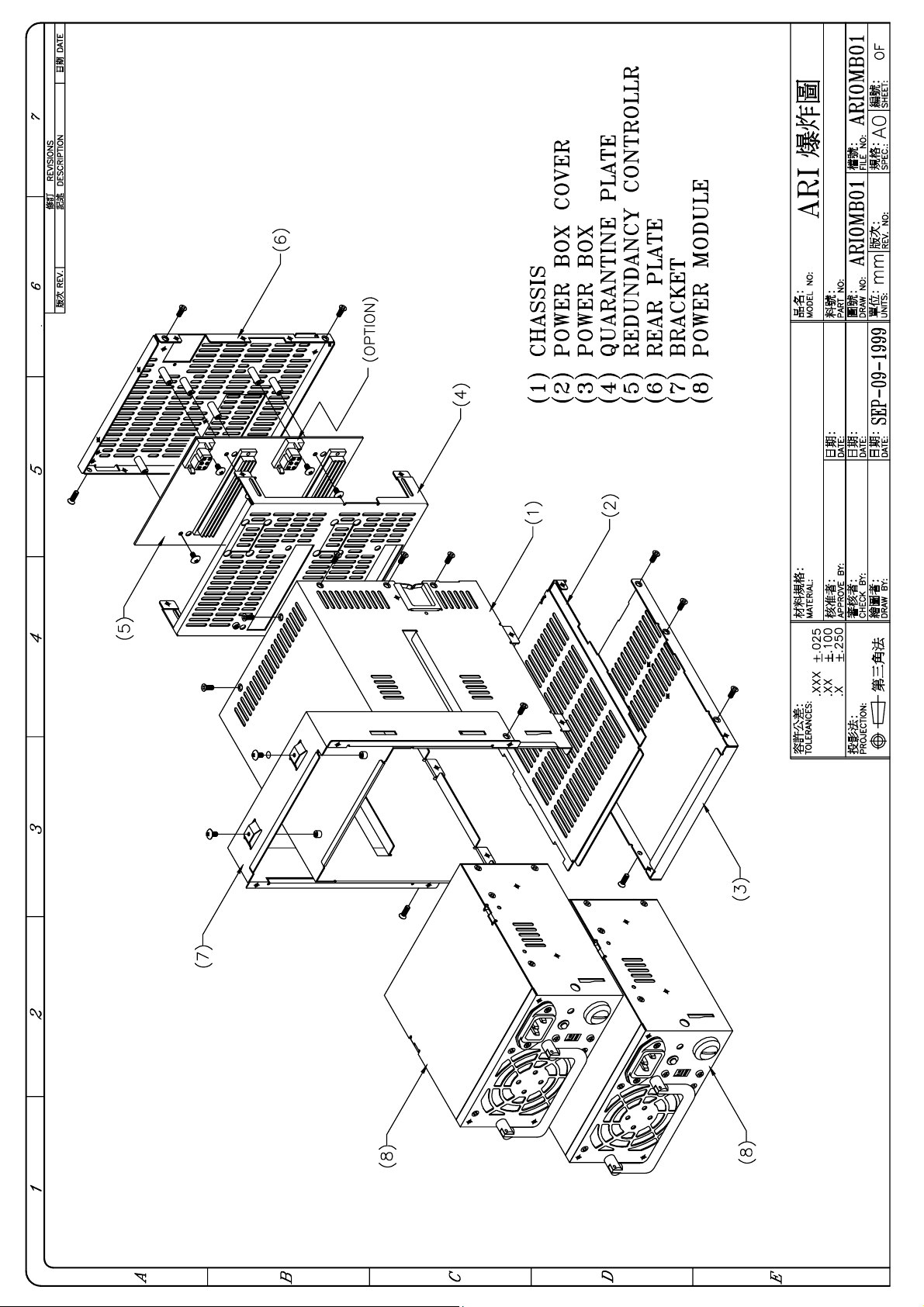
Y our ARX is a Redundant Switching Power Supply set, it consist of
(1) Complete metal frame
(2) Two power modules with HOT-PLUGGABLE capability
(3) Power sharing board / backplane
It delivers full safety redundant (hot-swappable) function and provides the hot-pluggable
feature. In other words, it can offer a more reliable and safer, easy install / maintain operation
in Power Supply to your computer system.
Its major function is the two power modules can mutually backup when one of the power
modules is defective. At the same time, it provides the warning subsystem for system
administrator use; it is LED display, buzzer alarm, power defective signal delivery, etc.
When both the power modules are at normal condition, it balances the load share and
increases the power supply system’s reliability.
To really discover the power and ease in using this product, we recommend that you read
through this manual carefully.
1.2. PACKING
Y our ARX box package should consist of the followings:
(A) 1 × ARX
(B) 1 × Product’s manual
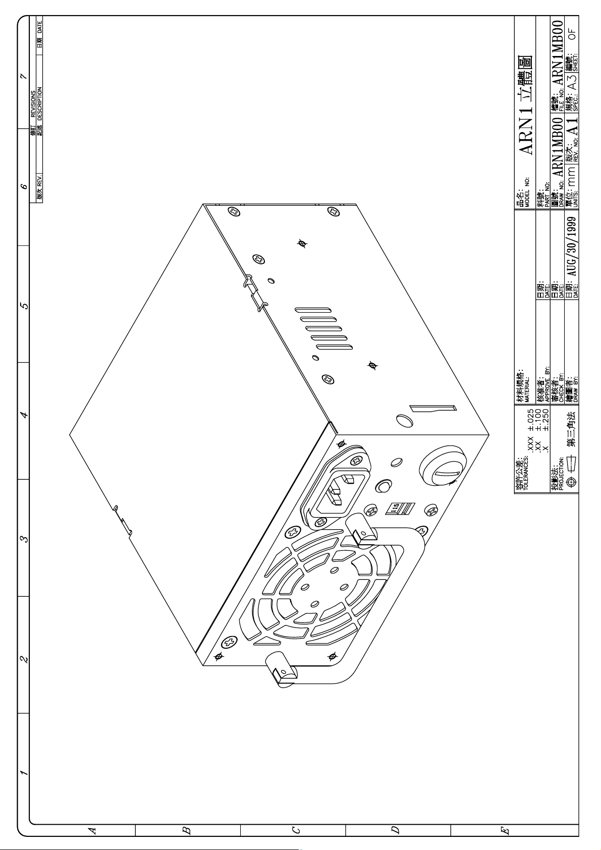
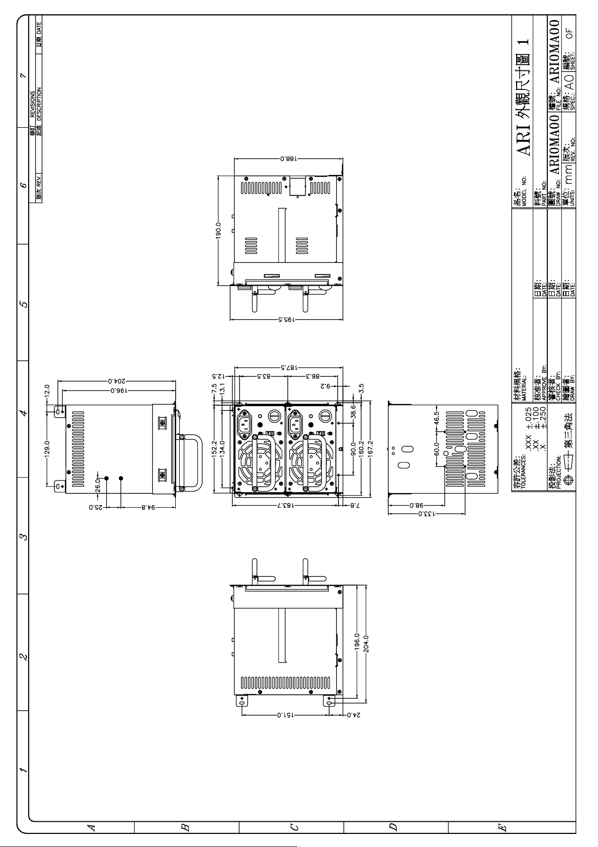
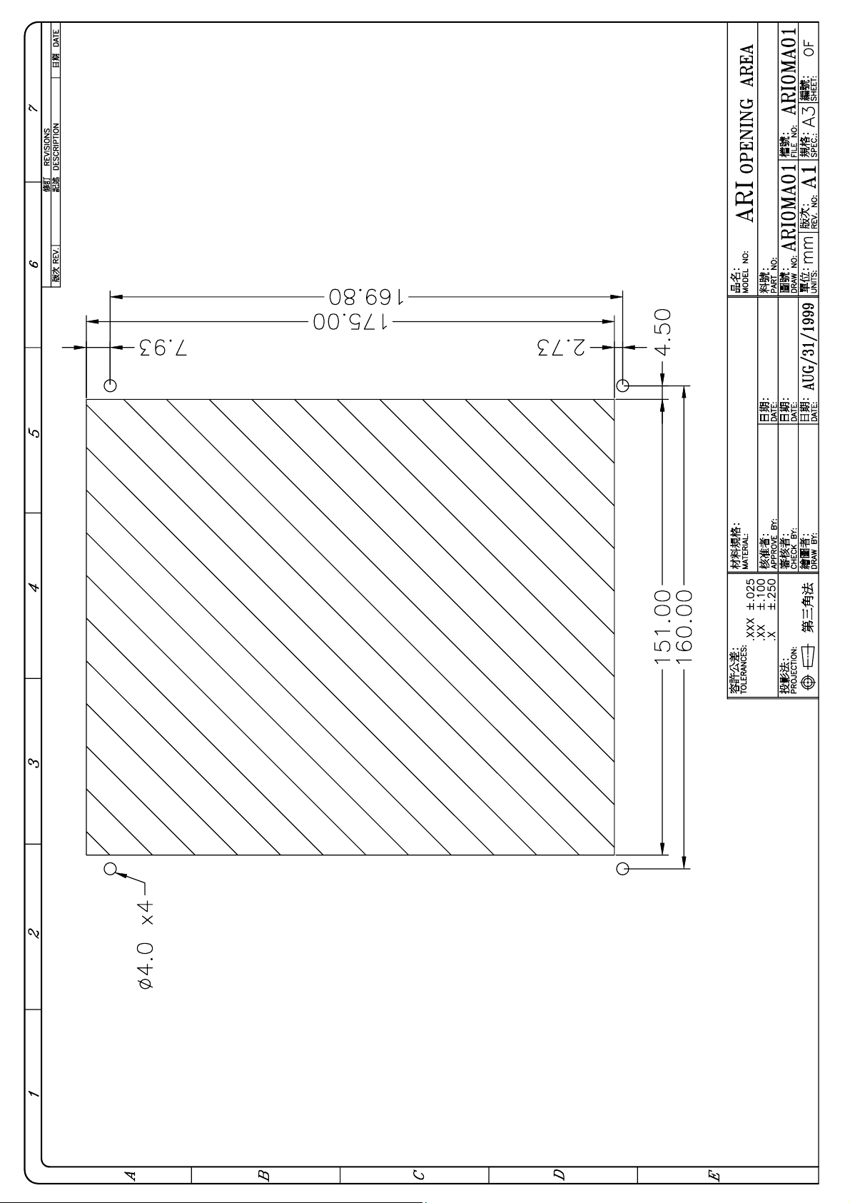
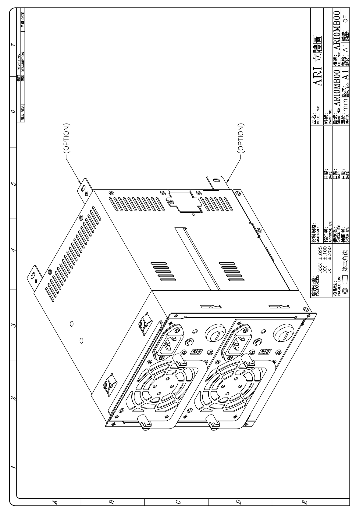
1.3. DRAWING
MODEL NUMBER IDENTIFICATION:
AR X
- X XXX X﹝X X XX﹞
AR ------ ADVANCED REDUNDANT POWER SUPPLY
FIRST X ------ D/I(Vertical Type)/H(Horizontal T ype) etc.
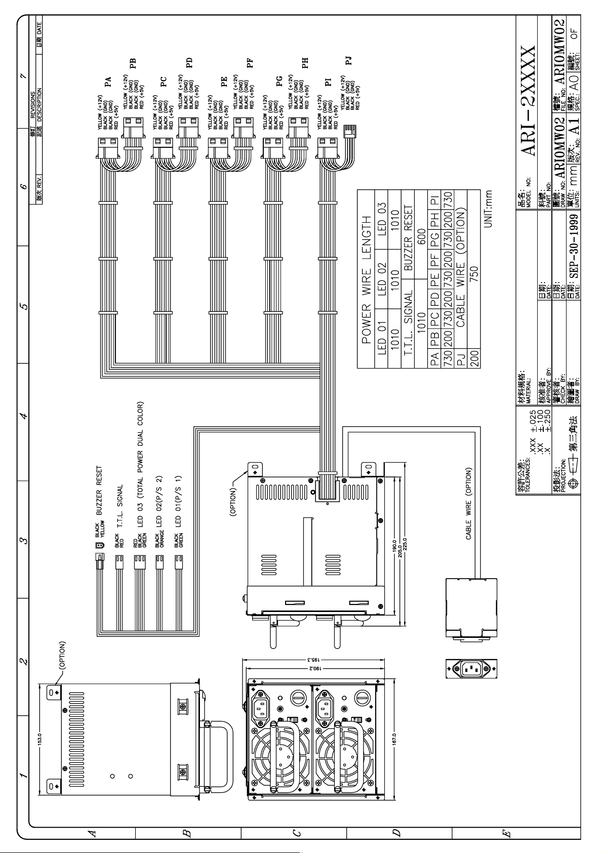
SECOND X ------- 2 STAND FOR 2 DC OUTPUTS (5/12V)
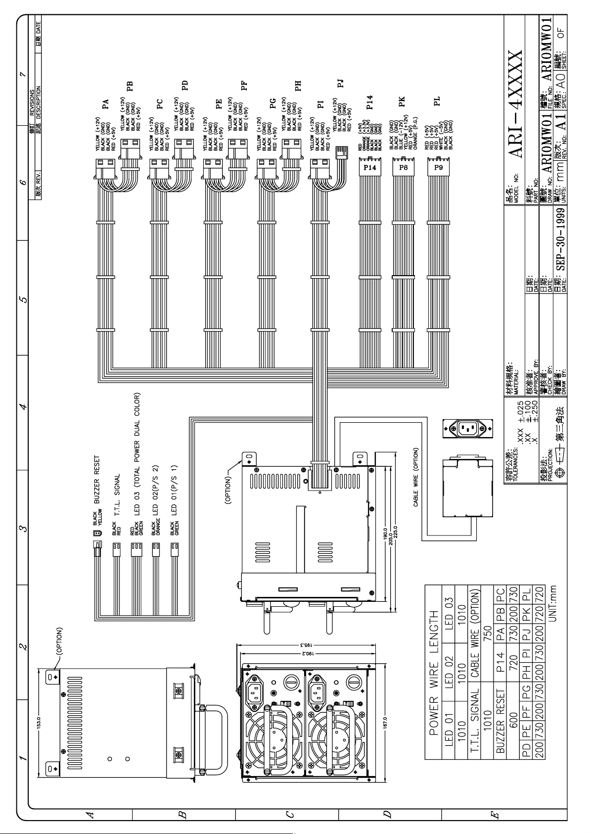
4 STAND FOR 4 DC OUTPUTS (5/12/-5/-12V)
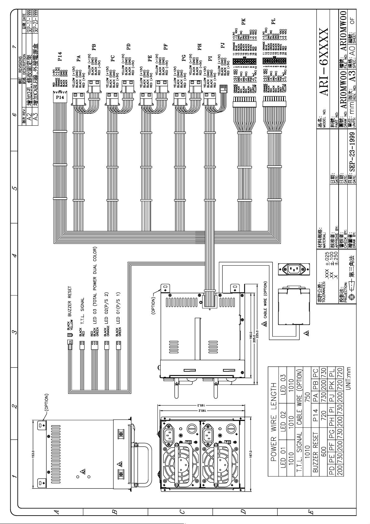
6 STAND FOR 6 DC OUTPUTS (5/12/-5/-12/3.3V/5V sb)
THIRD XXX ------ OUTPUTS WATTS (300/400)
FOURTH X ------ F STAND FOR POWER SOURCE ON FRONT SIDE
BLANK STAND FOR POWER SOURCE ON THE REAR SIDE
FIFTH X ------ D STAND FOR DC POWER INPUT
BLANK STAND FOR AC POWER SOURCE INPUT
SIXTH X ------ OPTIONAL FUNCTION(A:AVS; P:PFC﹣AC INPUT)
OPTIONAL FUNCTION(A:12V,B:24V,D:48V﹣DC INPUT)
SEVENTH XX ------ VERSION
Page 4
Page 5
Page 6
Page 7
Page 8
Page 9
Page 10
Page 11
Page 12

Page 13

Page 14

Page 15

Page 16

Page 17

Page 18

Page 19

Page 20

Page 21

Page 22

Page 23

Page 24

Page 25

Page 26

Page 27

Page 28

Page 29

INPUT CHARACTERISTICS: ARD / I – 2/4/6400F
VOLTAGE: 90 – 132 VAC / 180 ~ 264 VAC SWITCHABLE
FREQUENCY : 47 ~ 63 Hz
INPUT CURRENT: 5.0 / 2.5A FOR 115 / 230 VAC PER POWER MODULE
( PARALLEL )
INRUSH CURRENT: 50A / 100A MAX. FOR 115 / 230 VAC
OUTPUT CHARACTERISTICS:
OUTPUT
VOLTAGE
5V** 7.0 20~36 40
12V** 2.5 17 20
-5V*** 0 0.8 1
-12V*** 0 0.8 1 -10%~+10%
3.3V* 3.0 0~25 30
+5VSB 0 1.0 1.2
OUTPUT CURRENT REGULATION OUTPUT
MIN.[A] MAX.[A] PEAK(A) LOAD LINE
5%
±
8%
±
10%
±
5%
±
5%
±
±
±
±
±
±
±
1%
1%
1%
1%
1%
1%
RIPPLE & NOISE
MAX. [P-P]
60mV
120mV
120mV
150mV
60mV
50mV
* MANUFACTURER SET AT 3.45 V
*TOTAL OUTPUT OF +5V AND + 3.3V NOT EXCEED 180 W
** For ARD/ I / H – 2400F ; **&*** For ARD/ I / H – 4400F
Total output max:400W
TEMPERATURE RANGE: OPERATING 0℃ --- 40℃
HOLD UP TIME: 16 ms MINIMUM AT FULL LOAD & NORMAL INPUT VOLTAGE
DIELECTRIC WITHSTAND: INPUT / OUTPUT 1500 VAC FOR 1 SECOND
INPUT TO FRAME GROUND 1500 VAC FOR 1 SECOND
EFFICIENCY: 65% TYPICAL, AT FULL LOAD
POWER GOOD SIGNAL: ON DELAY 100 ms TO 500 ms, OFF DELAY 1 ms
OVER LOAD PROTECTION: 130 +/- 20%
OVER VOLTAGE PROTECTION:
+5V 6.0V ~ 7V, 3.3V 4.0 ~ 4.5V, ( EACH POWER MODULE )
OVER CURRENT PROTECTION : SHORT CIRCUIT
EMI NOISE FILTER: FCC CLASS B, CISPR22 CLASS B
SAFETY: UL 1950, CSA 22.2 NO/ 950, TÜV IEC 950
REMOTE ON / OFF CONTROL
THE UNIT SHALL ACCEPT A LOGIC OPEN COLLECTOR LEVEL WHICH WILL
DISABLE / ENABLE ALL THE OUTPUT VOLTAGE (EXCLUDE +5V STANDBY),
AS LOGIC LEVEL IS LOW, OUTPUTS VOLTAGE WERE ENABLE,
AS LOGIC LEVEL IS HIGH, OUTPUTS VOLTAGE WERE DISABLE.
HOT-SWAPPABLE / HOT-PLUGGABLE REDUNDANCY FUNCTION
BALANCE LOAD SHARING DESIGN
REMOTE SENSING DESIGN
ISOLATION: BUILT-IN IN THE POWER MODULE
PASSIVE BACKPLANE DESIGN
DIMENSION: ARD: 153(W) x 212(H) x 190(D); ARI: 167(W) x 189(H) x 190 (D);
CONNECTION: 48 PINS CONNECTOR (EPT PART NO. 109-40064 OR EQUIVALENT)
6 PINS CONNECTOR (POSITRONIC PART NO. PLB06M8000 OR
2
I
C COMMUNICATION ABILITY (OPTIONAL)
EQUIVALENT) OPTIONAL FOR INPUT SOURCE FROM REAR SIDE
Revision: A01
Page 30

INPUT CHARACTERISTICS: ARD / I – 2/4/6300F
VOLTAGE: 90 – 132 VAC / 180 ~ 264 VAC SWITCHABLE
FREQUENCY : 47 ~ 63 Hz
INPUT CURRENT: 5.0 / 2.5A FOR 115 / 230 VAC PER POWER MODULE
( PARALLEL )
INRUSH CURRENT: 50A / 100A MAX. FOR 115 / 230 VAC
OUTPUT CHARACTERISTICS:
OUTPUT
VOLTAGE
5V** 7.0 20~36 40
12V** 2.5 17 20
-5V*** 0 0.8 1
-12V*** 0 0.8 1 -10%~+10%
3.3V* 3.0 0~25 30
+5VSB 0 1.0 1.2
OUTPUT CURRENT REGULATION OUTPUT
MIN.[A] MAX.[A] PEAK(A) LOAD LINE
5%
±
8%
±
10%
±
5%
±
5%
±
±
±
±
±
±
±
1%
1%
1%
1%
1%
1%
RIPPLE & NOISE
MAX. [P-P]
60mV
120mV
120mV
150mV
60mV
50mV
* MANUFACTURER SET AT 3.45 V
*TOTAL OUTPUT OF +5V AND + 3.3V NOT EXCEED 180 W
** For ARD/ I / H – 2300F ; **&*** For ARD/ I / H – 4300F
Total output max:300W
TEMPERATURE RANGE: OPERATING 0℃ --- 40℃
HOLD UP TIME: 16 ms MINIMUM AT FULL LOAD & NORMAL INPUT VOLTAGE
DIELECTRIC WITHSTAND: INPUT / OUTPUT 1500 VAC FOR 1 SECOND
INPUT TO FRAME GROUND 1500 VAC FOR 1 SECOND
EFFICIENCY: 65% TYPICAL, AT FULL LOAD
POWER GOOD SIGNAL: ON DELAY 100 ms TO 500 ms, OFF DELAY 1 ms
OVER LOAD PROTECTION: 130 +/- 20%
OVER VOLTAGE PROTECTION:
+5V 6.0V ~ 7V, 3.3V 4.0 ~ 4.5V, ( EACH POWER MODULE )
OVER CURRENT PROTECTION : SHORT CIRCUIT
EMI NOISE FILTER: FCC CLASS B, CISPR22 CLASS B
SAFETY: UL 1950, CSA 22.2 NO/ 950, TÜV IEC 950
REMOTE ON / OFF CONTROL
THE UNIT SHALL ACCEPT A LOGIC OPEN COLLECTOR LEVEL WHICH WILL
DISABLE / ENABLE ALL THE OUTPUT VOLTAGE (EXCLUDE +5V STANDBY),
AS LOGIC LEVEL IS LOW, OUTPUTS VOLTAGE WERE ENABLE,
AS LOGIC LEVEL IS HIGH, OUTPUTS VOLTAGE WERE DISABLE.
HOT-SWAPPABLE / HOT-PLUGGABLE REDUNDANCY FUNCTION
BALANCE LOAD SHARING DESIGN
REMOTE SENSING DESIGN
ISOLATION: BUILT-IN IN THE POWER MODULE
PASSIVE BACKPLANE DESIGN
DIMENSION: ARD: 153(W) x 212(H) x 190(D); ARI: 167(W) x 189(H) x 190 (D);
CONNECTION: 48 PINS CONNECTOR (EPT PART NO. 109-40064 OR EQUIVALENT)
6 PINS CONNECTOR (POSITRONIC PART NO. PLB06M8000 OR
2
I
C COMMUNICATION ABILITY (OPTIONAL)
EQUIVALENT) OPTIONAL FOR INPUT SOURCE FROM REAR SIDE
Revision: A01
Page 31

1.4. FEATURES
A
REDUNDANCY
HOT-SWAP
FUNCTION
BUZZER
POWER DEFECTIVE
SIGNAL
LEDS
HOT-PLUGGABLE
FUNCTION
SAFETY
RELIABILITY
COMPATIBILITY
Independent DC Outputs and passive backplane design
ensure redundant function been performed for computer
system. Balance Share loading with no transfer time when
backup takes place.
The power system provides a HOT-SWAP function. This
means when one of the redundant power module fails or
breaks down, you can easily replace failed unit without any
interference to the system.
warning buzzer sounds when any one of the power module
fails. The warning buzzer is resettable from either the front
control panel or switch on the rear side.
The unit provides a power defective signal through the proper
card to acknowledge the system
The warning LEDs can be found either on the rear side or the
control panel of the power system. Tells if one of the two
power modules failed, by LED changing color.
The power system provides tool-free Hot-Pluggable function.
This allows the power units in the Disk Array/File Serv er to be
removed or inserted very easily without opening and closing
the chassis.
Since the power system used isolated fence and power
supply Last Contact / First Release (LCFR) prevents a
person from being shocked by high AC voltage during the
installation or HOT-Swap procedure. UL, UL+C, TUV, CB
approved.
The power unit’s ON / OFF is controlled by the use of a very
small DC current, this prevents damage the power system.
Besides, it uses heavy-duty connector, align guide increase
reliability.
The enclosure of the power system is well designed, so
under proper arrangement / assembly, the redundant power
supply can built to various form factors such as RPD / RPI.
Besides, its input power sources can be located on
the
alternative position to meet various applications, such as
power system located on the front side of the rackmount
chassis, and power source from the rear side.
REMOTE SENSE The power system is designed with remote sensing feature:
this makes the regulation of voltages more excellent.
I2C INTERFACE
(OPTIONAL)
The unit provides communication ability through I2C,
system
administrator can monitor/ manage the power system
Page 32

1.6. INSTALLATION & TESTING
Turn off (remote off) the on / off switch
Mount the power supply in the system chassis using the proper mounting hardware, the
mounting
holes in the power supply should match up with those in the case. Attach the connectors to the
motherboard by following the motherboard’s instructions, there are various on
connectors/pinouts
in both the power supply and motherboard. They should match each other; otherwise the
connection will cause undetectable harms.
Attach all the remaining power supply connections to the various peripherals as needed,
these connectors are “keyed”, so there will be only one possible way to connect them.
Before applying power to the system, make sure there are no loose or incorrect connections.
The input voltage has been set to the correct volt age (110/220 VAC, the voltage selector lo cate
at DC fan side), double check that all connection to the motherboard are properly matched.
May be you would like to test the redundancy function before you put back the cover of your
system chassis. Turn on / remote on the on/off switch, you will notice that if the power unit is
operating properly, then individual LEDs, external warning LEDs (Please refer to Sec. 1.9 for
detail explanation) are lit GREEN, now remove one of the power modules, the Warning Buzzer
in the power system will sound, and the external warning LED which display the status of the
total power supply system will change color to be RED, the individual LEDs (both on the rear
side or on the front control panel) indicating the power supply’s status will not light. Meanwhile
the power supply will continue to backup the power output without affecting the computer
system’s operation.
The Warning Buzzer will continue sounding, the user can reset the Warning Buzzer by
pressing the buzzer reset switch at the rear side, refer to the drawing on Sec. 1.3, or use the
reset switch which can be found on the front control panel of the system chassis, the reset
switch can be connected by wires lead provided from the power supply system (Please refer to
Sec. 1.9).
Insert the power module which is removed for testing earlier, the sound of the Warning Buzzer
will disappear , the external warning LE D will turn GRE E N again. Th e LED indi cat ing the status
of the power supply will light again, test another power supply by performing the similar
procedure.
If you use the power defective signal, there are two pins connector (refer to the drawing on Sec
1.3 and table on Sec. 1.9), it should be connected to the FAB-5 card properly, please refer its
User’s Manual.
.
Page 33

If everything works out fine, then turn off (remote off) the power system, now put back the
cover of the case and tighten then with the screws which you have retained earlier. Now you
have completed the installation of the ARX redundant power supply system.
1.7. HOT-SWAP PROCEDURES
Please refer to the following when either one-power module found defective.
A) Locate the defective power module by examining the individual LED or the LED on the
front control panel. (If LED is not light, it indicated the power module is defective).
WARNING:
“PLEASE PERFORM THE ABOVE STEP CAREFULLY OTHERWISE IT MAY CAUSE
SHUT DOWN THE WHOLE SYSTEM”.
B) Unplug the power co rd which bel ongs to the defective power module from the AC/DC inlet.
C) Unlock the lock which fix the defective power module.
D) Remove the defective power module by pulling out method.
E) Replace a new GOOD power module, set the proper AC/DC input voltage, and insert the
power module into the power supply system chassis.
F) Plug the power cord which is unplugged earlier.
G) Check the LEDs which indicate the total power system status that SHOULD be from RED
to GREEN.
H) Fix the new power module by locking the lock.
I) If you want to test the NEW power module in simulating defective situation, please refer to
the section 1.6 INSTALLATION & TESTING Section.
Page 34

1.8. PINOUTS AND FUNCTION OF THE CONNECTORS
***PLEASE AW ARE THE POLARITY
THE LED CONNECTOR OF POWER #1
PIN# COLOR VOLTAGE
1 GREEN +5V
2 BLACK GND
THE LED CONNECTOR OF POWER #2
PIN# COLOR VOLTAGE
1 ORANGE +5V
2 BLACK GND
THE LED CONNECTOR OF TOTAL POWER SYSTEM
PIN# COLOR VOLTAGE
1 BLUE +5V
2 BLACK GND
THE BUZZER RESET SWITCH CONNECTOR
PIN# COLOR VOLTAGE
1 YELLOW +12V
2 BLACK GND
THE SIGNAL CONNECTOR OF POWER DEFECT
PIN# COLOR VOLTAGE
1 RED TTL SIGNAL
2 BLACK GND
THE SIGNAL CONNECTOR OF I2C (OPTIONAL)
PIN# COLOR VOLTAGE
1 GREEN SDA
Page 35

2 WHITE SCL
A
p
1.9. TROUBLE SHOOTING
If you have followed these directions correctly, there should be no problem. Same common
symptoms are: the system doesn’t work, buzzer sound, work for a very short period, etc.,
please try the following steps to verify and correct it:
1. Check all the connections (correct pinouts, loose connections, wrong direction, etc.)
2. Check for short-circuits or defective peripherals by unhooking each peripheral once at a
time. When the systems functions again, you have solved the problem.
3. Once you hear the buzzer sound or see the LED with RED light, please be aware of:
a. IF the load is under the minimum / over the maximum load of each channel (Please
refer the sec. 1.5 Specification)?
b. IF AC/DC input voltage been set correct?
c. IF each power cord been well plugged into the inlet?
Suppose the above condition been happened, please unplug the power cords, await for 2 – 3
minutes for releasing the protection state, then test it again.
d. IF buzzer still sound or the LED shows power module is defective, please locating
which power module is defective, perform hot-swap procedure (please refer to the
HOT-SWAP PROCEDURES), send the defective power module to your vendor for
RMA operation.
e. IF you can not fix the problem, please contact with your vendor for supporting.
The description stated herein is subject to
change without prior notice.
ll brand names and trademarks are the
roperty of their respective owners.
Page 36

The “RELIABILITY “ solution to E-application
新巨企業股份有限公司
ZIPPY TECHNOLOGY CORP.
POWER DIVISION
HEADQUARTERS
10F, NO. 50, MIN CHYUAN RD., SHIN-TIEN CITY,
TAIPEI HSIEN, TAIWAN, R.O.C.
TEL: 886-2-29188512 FAX: 886-2-29134969
WEB SITE: http://www.zippy.com.tw E-mail:power@zippy.com.tw
USA OFFICE
U.S. East (Atlantic)
11 Melanie Lane, Unit 1B East Hanover, NJ 07936
TEL:1-973-463-9499 FAX:1-973-453-8014
E-mail:edward@zippy.com
U.S. W est (Pacific)
961 CALLE NEGOCIO, SAN CLEMENTE CA 92673, USA
TEL: 1-949 366 9525 FAX: 1- 949 366 9526
EMAIL: powerusa@zippy.com
CANADA OFFICE
ZIPPY TECHNOLOGY CANADA INC.
Unit3-3671 Viking Way Richmond, B.C V6V 2J5 Canada
TEL:1-604-278-6615 FAX:1-604-278-6624
CELL: 1-778-288-9622 E-mail:ian@zippy.com
Note:
*The description stated herein is subject to change without prior notice.
*All brand names and trademarks are the property of their respective owners
 Loading...