

Page 1
Owner’s Manual
Digital Ignition Module for 2004-up
Carbureted Harley Davidson Motorcycles
P/N 309-575
This product is legal in California only for racing vehicles which may never be used upon a highway.
Thunder Heart Performance Corporation MANUAL P/N EI5077
120 Industrial Drive Revision 11/4/08
White House, TN 37188
www.thunder-heart.com
Page 2

Page 3

Thunder Heart Performance Corp. 615-672-8811 www.thunder-heart.com
TABLE OF CONTENTS
CHAPTER 1 INTRODUCTION ...............................................1
CHAPTER 2 IGNITION INSTALLATION ................................ 2
2.1 Dyna Models ..............................................................................2
2.2 Touring Models...........................................................................2
2.3 Softail Models.............................................................................3
2.4 Sportster Models........................................................................3
CHAPTER 3 AUXILIARY INPUTS/OUTPUTS .......................4
CHAPTER 4 IGNITION MODULE PROGRAMMING .............5
4.1 Ignition Programming Using Built-In Buttons .............................5
4.2 Ignition Programming the (Available Separately) SmartLink
Software and Interface Cable..............................................................6
CHAPTER 5 IGNITION OPERATION..................................... 6
WARRANTY..............................................................................7
CONTACTING THUNDER HEART PERFORMANCE CORP.
Mailing Address................................P.O. Box 76
White House, TN 37188
Shipping Address .............................120 Industrial Drive
White House, TN 37188
Phone ...............................................615-672-8811
Fax....................................................615-672-1353
Tech Support E-mail.........................techsupport@thunder-heart.com
Website.............................................www.thunder-heart.com
309-575 TH-Zip Ignition.doc I
Page 4

Page 5

Thunder Heart Performance Corp. 615-672-8811 www.thunder-heart.com
CHAPTER 1 INTRODUCTION
Zipper’s Performance Products and Thunder Heart Performance Corporation
have joined forces as the “J1850 Alliance” to create products that are “J1850
compatible” for 2004-later Harleys. Thunder Heart’s cutting-edge technology
combine with Zipper’s expertise in performance to provide the rider with the
best products possible.
The latest product of this alliance is their Digital Ignition Module for 2004-later
carbureted Harleys
Users can program the module by either using the module-mounted
pushbuttons and digital display, or using the (sold separately) Smartlink
Software and Interface Cable. Users can also “offset” a pre-programmed
curve up to +/-5 degrees without having to link the software up to the module!
The ASM5075 has three additional outputs to control a “2-Stage” rev limiter,
a shift light, and an analog tachometer output for use with most aftermarket
tachometers. It’s a great way to configure the ZAP on your 2004-later
Harley!
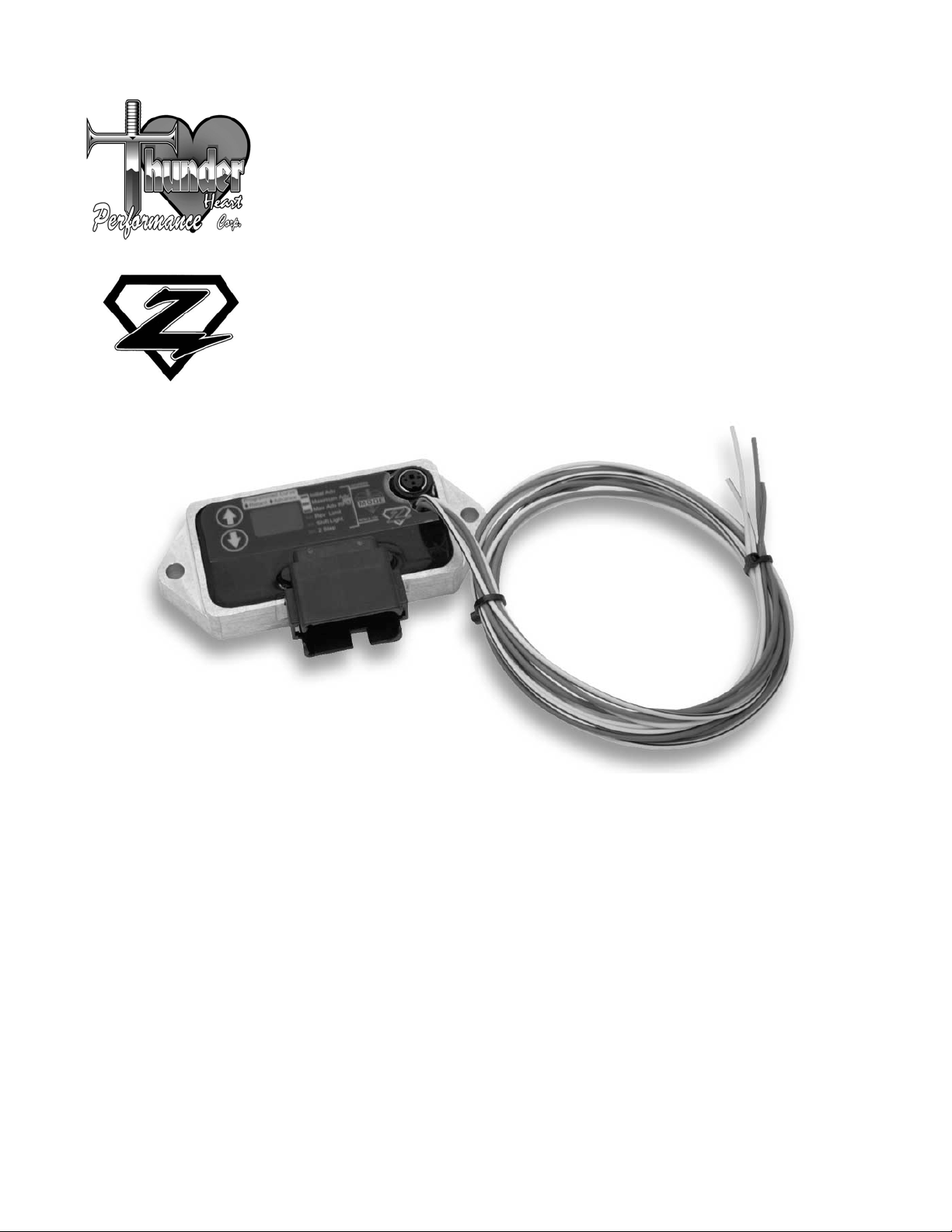
Figure 1—Digital Ignition Module component identification
309-575 TH-Zip Ignition.doc 1
Page 6

Thunder Heart Performance Corp. 615-672-8811 www.thunder-heart.com
CHAPTER 2 IGNITION INSTALLATION
2.1 Dyna Models
1. Disconnect the negative battery cable.
2. Grasp the sides of the electrical caddy (located next the ignition coil) and
pull outward to remove.
3. Remove the relay and fuse panels from the electrical caddy.
a. Insert a small screwdriver into the slot under each fuse and relay
panel.
b. Using a screwdriver, disengage the panel from the electrical caddy.
4. Disconnect the main fuse connector from the electrical caddy
a. Remove the main fuse from the connector
b. Insert small screwdrivers into the slots on each side of the main fuse
c. Depress the tabs of the main fuse connector to disengage it from the
electrical caddy
5. Depress the tab located on the electrical caddy securing the TSM/TSSM.
Pull it from the electrical caddy. Disconnect the TSM/TSSM connector.
6. Slide the data link connector towards the front of the motorcycle to
disengage it from the electrical caddy.
7. Disconnect the ignition control module connector.
8. Disconnect the ignition coil connector and spark plug cables from the
coil.
9. Remove the electrical caddy fasteners (3 total).
10. Remove the wiring from the electrical caddy.
11. Remove the fasteners securing the factory ignition control module from
the electrical caddy.
12. Installation of the Digital Ignition Module is the reverse of removal.
2.2 Touring Models
1. Disconnect the negative battery cable.
2. Remove the right saddlebag.
3. Gently pull the side cover from the frame downtubes (no tools required).
2 309-575 TH-Zip Ignition.doc
Page 7

Thunder Heart Performance Corp. 615-672-8811 www.thunder-heart.com
4. Depress the external latches and use a rocking motion to remove the
electrical connector from the ignition control module.
5. Remove the two socket screws to detach the ignition control module
from the electrical bracket.
6. To install the Digital Ignition Module, install and tighten the socket screws
to 50-60 in-lbs. The remainder of installation is the reverse of removal.
2.3 Softail Models
1. Remove the seat.
2. Disconnect the negative battery cable.
3. Remove the two screws to free the ignition control module from the
mounting bracket.
4. Depress the external latches and use a rocking motion to remove the
electrical connector from the ignition control module.
5. To install the Digital Ignition Module, install and tighten the socket screws
to 15-21 in-lbs. The remainder of installation is the reverse of removal.
2.4 Sportster Models
1. Remove the seat.
2. Disconnect the negative battery cable from the crankcase, and
disconnect the positive battery cable from the battery.
3. Depress the external latches and use a rocking motion to remove the
electrical connector from the ignition control module.
4. Remove the two lock nuts securing the ignition module from the
motorcycle.
5. To install the Digital Ignition Module, install and tighten the lock nuts to
12-15 in-lbs. The remainder of installation is the reverse of removal.
309-575 TH-Zip Ignition.doc 3
Page 8

Thunder Heart Performance Corp. 615-672-8811 www.thunder-heart.com
CHAPTER 3 AUXILIARY INPUTS/OUTPUTS
The Digital Ignition Module is supplied with additional auxiliary inputs and
outputs. These are “flying leads” that run directly from the ignition module.
face (see Figure 1). Use the following wiring diagram to hook up these
features:
Shift Light (Red with Yellow Stripe)
This wire supplies ground to a shift light. Connect the other wire of your shift
light to 12v+
2-Step Rev Limiter (Yellow with Black Stripe)
When this wire is grounded, the 2-step rev limiter is activated. This is
generally connected to a momentary pushbutton that connects to ground.
Tachometer Signal (Green)
Connect this wire to the signal input of an aftermarket tachometer.
4 309-575 TH-Zip Ignition.doc
Page 9

Thunder Heart Performance Corp. 615-672-8811 www.thunder-heart.com
CHAPTER 4 IGNITION MODULE PROGRAMMING
The Digital Ignition Module can be programmed one of two ways: with the
built-in MODE and ARROW buttons, or with the (available separately)
SmartLink cable and software.
4.1 Ignition Progra mming Using Built-In Buttons
To program the Digital Ignition Module using the built-in buttons on the face
of the ignition, follow this procedure:
1. Turn the motorcycle key to ON, but do not start the motorcycle.
2. Press the MODE button to select “Initial Adv.”
3. Use the arrow keys to select the desired initial advance.
4. Press the MODE button to select “Maximum Adv.”
5. Use the arrow keys to select the desired maximum advance.
6. Press the MODE button to select “Max Adv RPM.”
7. Use the arrow keys to select the desired maximum advance.
309-575 TH-Zip Ignition.doc 5
Page 10

Thunder Heart Performance Corp. 615-672-8811 www.thunder-heart.com
8. To program the other features of the Digital Ignition Module, use the
MODE and “arrow” buttons. The following is a list of each feature and its
range:
Initial Advance (Initial Adv) is the ignition timing in crankshaft degrees
(before top dead center), the module will use until 1000rpm.
Range: 5-20 degrees
Maximum Advance (Maximum Adv) is the ignition timing in crankshaft
degrees (before top dead center), the module will use as its maximum value.
Range: 24-45 degrees
Maximum Advance RPM (Max Adv RPM) is the engine speed (in RPM X
100) that the ignition reaches its maximum advance value. A lower RPM
makes the advance slope “steeper.”
Range: 2000-5300 RPM
Rev Limit Activation (Rev Limit) is the engine speed (in RPM X 100) that
the ignition’s main rev limiter is activated. Under acceleration, the engine will
not rev past this point.
Range: 5100 to 8000 RPM
Shift Light Activation (Shift Light) is the minimum engine speed (in RPM X
100) the ignition will supply a 12v+ signal to the red w/yellow stripe auxiliary
output wire.
Range: 5100 to 8000 RPM
2-Step Rev Limit Activation (2-Step) is the engine speed (in RPM X 100)
that the ignition will limit the engine when the yellow w/black strip auxiliary
input wire is grounded (useful for drag racing).
Range: 2000 to 5100 RPM
4.2 Ignition Programming Using (Available Separately) SmartLink Software and Interface Cable
To program the Digital Ignition Module with the SmartLink Software and
Interface Cable, please refer to the instructions supplied with that kit.
CHAPTER 5 IGNITION OPERATION
When the motorcycle is running, the current ignition timing will appear on the
display.
6 309-575 TH-Zip Ignition.doc
Page 11

Thunder Heart Performance Corp. 615-672-8811 www.thunder-heart.com
Note: The value displayed may differ slightly from the value you programmed
because the ignition automatically adds a few degrees of advance based
upon manifold vacuum. This is for improved part-throttle and cruising
performance. The values you programmed will be used for wide-open-throttle
situations.
WARRANTY
Thunder Heart Performance Corp. will repair or replace any parts that have
manufacturing defects only under the following conditions:
• The customer must return the product to the original place of purchase.
• The product must be returned within one year of the original distribution
sale date.
• All returns must be accompanied with a copy of the receipt.
• The product must be individually tagged with a completed description of
the problem or defect.
• All returned items must be packaged and shipped in the same manner
as Thunder Heart originally shipped them to the dealer.
Thunder Heart Performance Corp. reserves the right to repair or replace the
product at Thunder Heart’s discretion. We do not offer refunds or credit for
the returned product. In addition, any product that is misused or otherwise
damaged by the end customer will be billed for any repair or replacement
costs associated with the damage.
309-575 TH-Zip Ignition.doc 7
Page 12

Thunder Heart Performance Corp. 615-672-8811 www.thunder-heart.com
NOTES:
8 309-575 TH-Zip Ignition.doc
 Loading...