

ZIP-CAM - Vol 1 / Version 1
www.ZipNVR.com
Instruction
Manual
Add more to your CCTV!...
...zippy to t & zippy to learn!
...Camera browser manual
IP-CAM530 / 535 / 570 / 800 / 815 / 870 / 880 / 910 / 920 / 930 Models

ZIP IPC User Manual

ZIP IPC USER MANUAL
TABLE OF CONTENTS Page
Contents 2
Special Note 3
1. Overview 4
1.1 Range of IP Address 4
1.2 Product Description 4
1.3 Operation Environment 4
2. IP Camera Connection 5
2.1 Connection direct to PC via a crossover cable 5
2.2 Connection direct to PC via a LAN/Patch cable 5
2.3 Connection to a router or switch 5
3. Device Operation Instructions 6
3.1 Check Connection 6
3.2 Searching for IP camera device using ZipFinder and changing IP etc. 6
3.3 Installation of Controls and Login to System 9
3.3.1 Preview 9
3.3.2 Playback (optional function) 12
4. Remote Setting 13
4.1 Camera 13
4.1.1 OSD Menu 13
4.1.2 Camera Settings 14
4.1.3 Privacy Mask 15
4.1.4 ROI (Region of Interest) 16
4.2 Record 17
4.2.1 Record Settings 17
4.2.2 Normal Schedule 18
4.2.3 Event Schedule 19
4.3 Network 20
4.3.1 Network Parameters 20
4.3.2 Encoding 21
4.3.3 E-Mail Configuration 22
4.3.4 DDNS Configuration 23
4.3.5 IP Filtering 24
4.3.6 RTSP 24
4.3.7 FTP 25
4.4 Alarm 26
4.4.1 Motion Detection 26
4.4.2 Alarm Settings 27
4.4.3 Lens Covered 27
4.5 Device 28
4.5.1 SD Card (optional function – available if menu displayed 28
4.5.2 Audio (optional function – available if audio lead on camera 28
4.5.3 Log 30

ZIP IPC USER MANUAL
3
4.6 System 31
4.6.1 Date and Time Information 31
4.6.2 Users 33
4.6.3 Information 34
4.6.4 Smart Analysis (CC) 34
4.7 Tools 35
4.7.1 Firmware Upgrade 35
4.7.2 Load Default 35
4.7.3 Reboot 36
4.8 Smart 37
4.8.1 Perimeter Intrusion 37
4.8.2 Line Crossing Detection (LCD) 38
4.8.3 Stationary Object Detection 39
4.8.4 Pedestrian Detection 40
4.8.5 Face Detection 42
4.8.6 Cross Counting (CC) 44
5. Local Setting 47
5.1 Local Setting Options 47
5.1.1 Record Path 47
5.1.2 Download Path 47
5.1.3 Snapshot (Capture) Path 47
5.1.4 File Type 47
5.1.5 Interval 47
SPECIAL NOTE:
The default factory IP address for the IP camera is 192.168.10.1
The default factory administrator username and password for this IP camera is
Username: admin Password: 777777
The default Web port number is: 80
The default media (management) port number is: 9988
All specifications are approximate. Kovert.com reserves the right to
change any product specification or features without notice. Whilst
every effort is made to ensure that these instructions are complete
and accurate, kovert.com cannot be held responsible in any way for
any losses, no matter how they arise, from errors or omissions in
these instructions, or the performance or non-performance of the
camera or other equipment that these instructions refer to.

ZIP IPC USER MANUAL
4
1. Overview
1.1 Range of IP Address
The ZIP range of IP cameras use an identical menu system which is detailed below. The default IP
address is 192.168.10.1. If you are connecting this camera to a network which is not on a
192.168.10 address, then you will have change the IP address in the camera. The safest way is to
connect this camera straight to a PC that is set to a 192.168.10 address using a crossover cable or
using the LCD390 test monitor. Other methods are covered in more detail later in this manual.
1.2 Product Description
The ZIP IP camera is a digital online surveillance camera embedded with a Web server and capable
of independent operation, giving the user access to real-time monitoring through a web browser.
The camera uses an integrated media processing platform for audio and video with H.264/ H265
High Profile encoding standards. Any remote user can have access to real-time monitoring by
entering the IP address or domain name of the IP camera in the web browser.
The IP cameras can be managed by several users with different authorisation levels.
IP cameras allow motion detection and send e-mails and can take snapshots in cases of emergency,
with the image or video snapshot stored on the internal SD card. Note that record times will vary
according to the size of the SD card but will normally be short due to the large storage space taken
by HD video and audio.
1.3 Operation Environment
Operating system: Windows 10 / Windows 7/ Windows 8 / Windows 2008 (32/64-bit),
Windows 2003 / Windows XP / Windows 2000 (32-bit)
CPU: Intel Core Duo II dual-core processor or higher
Memory: 1G or more Video memory: 256M or more
Display: 1024 × 768 or higher resolution
IE: IE 6.0 or higher version

ZIP IPC USER MANUAL
5
2. IP Camera Connection
2.1 Connection direct to PC via a crossover cable
Connect IP camera to a PC via a crossover cable, with power input connected to a DC 12V power
supply and set the IP addresses of the PC and IP camera in the same network subnet. The IP camera
will communicate with the PC if the IP address in the camera is changed so that it is in the same
subnet as the PC. This can be done prior to connecting IP camera to a network.
2.2 Connection direct to PC via a LAN/Patch cable
Connect IP camera to a PC via a LAN/Patch cable, with power input connected to a DC 12V power
supply and set the IP addresses of the PC and IP camera in the same network subnet. The IP camera
will communicate with the PC within one minute if the IP address in the camera is changed so that
it is in the same subnet as the PC.
2.3 Connection to a router or switch
The most common use is connecting the IP camera to the Internet, where the camera and PC are
connected to LAN ports on a router or switch, with the gateway of the camera and PC set to the IP
address of the router.
Crossover Cable
LAN/Patch Cable
ZIP IPC USER MANUAL
6
3. Device Operation Instructions
3.1 Check Connection
1. The default factory IP address for the IP camera is 192.168.10.1 and the subnet mask is
255.255.255.0. Change your computer IP address to the same network subnet as the IP camera, for
example: IP Address of PC to 192.168.10.100 and subnet mask 255.255.255.0 same as that of the
IP camera.
2. Example: To test whether the IP camera is connected properly try pinging it, by clicking on
the Windows button and the letter ‘R’ on the PC keyboard, entering the Run box in left hand corner
of screen and entering “CMD” and click OK to display a black MSDOS screen with a flashing
cursor.
Then type <PING 192.168.10.1> (or IP address of IP camera)
Display should confirm the following:
pinging IP address 192.168.10.1 - four times
and - Packets Sent = 4, Received = 4, Lost = 0.
3. This indicates that the IP camera operates normally and the network is connected properly.
3.2 Searching for IP camera device using ZipFinder and changing IP etc.
ZipFinder may be used for searching and changing IP devices on a network. This program will be
found on the client CD software disk supplied with the IP camera. To run ZipFinder click on the
local connection icon on the desktop. Note that this tool must be used with care and must be
removed once the IP addressing is completed.
1. First go onto the Windows PC and add an IP address in the range of the IP default address so
the IP cameras that can be detected by your PC. Then by running ZipFinder you can search any
device within the IP address range of the IP camera and the existing PC IP address range.
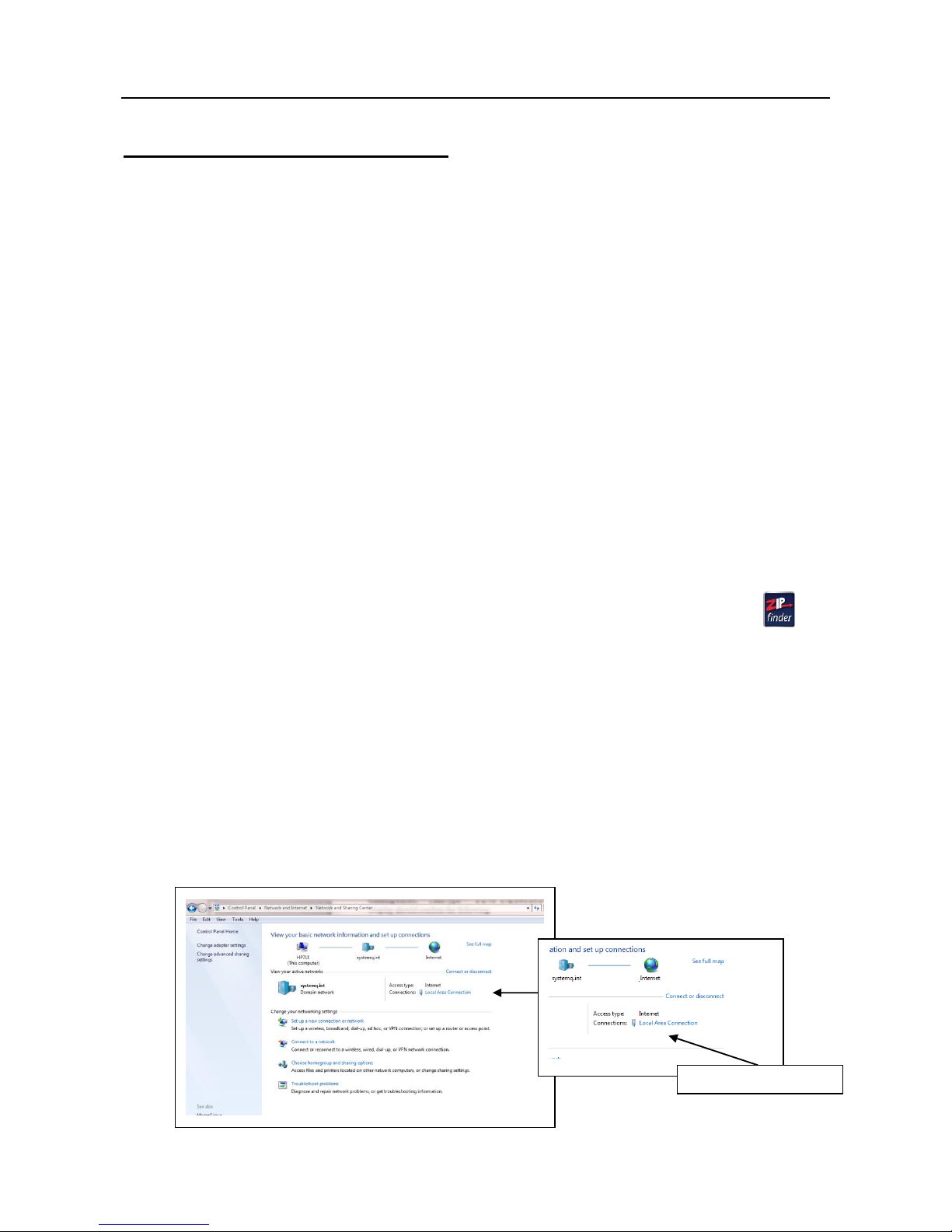
Step A
Go to Control Panel, Network and Internet, Networking and Sharing Centre and then click on
Local Area Connection.
Local Area Connection
ZIP IPC USER MANUAL
7
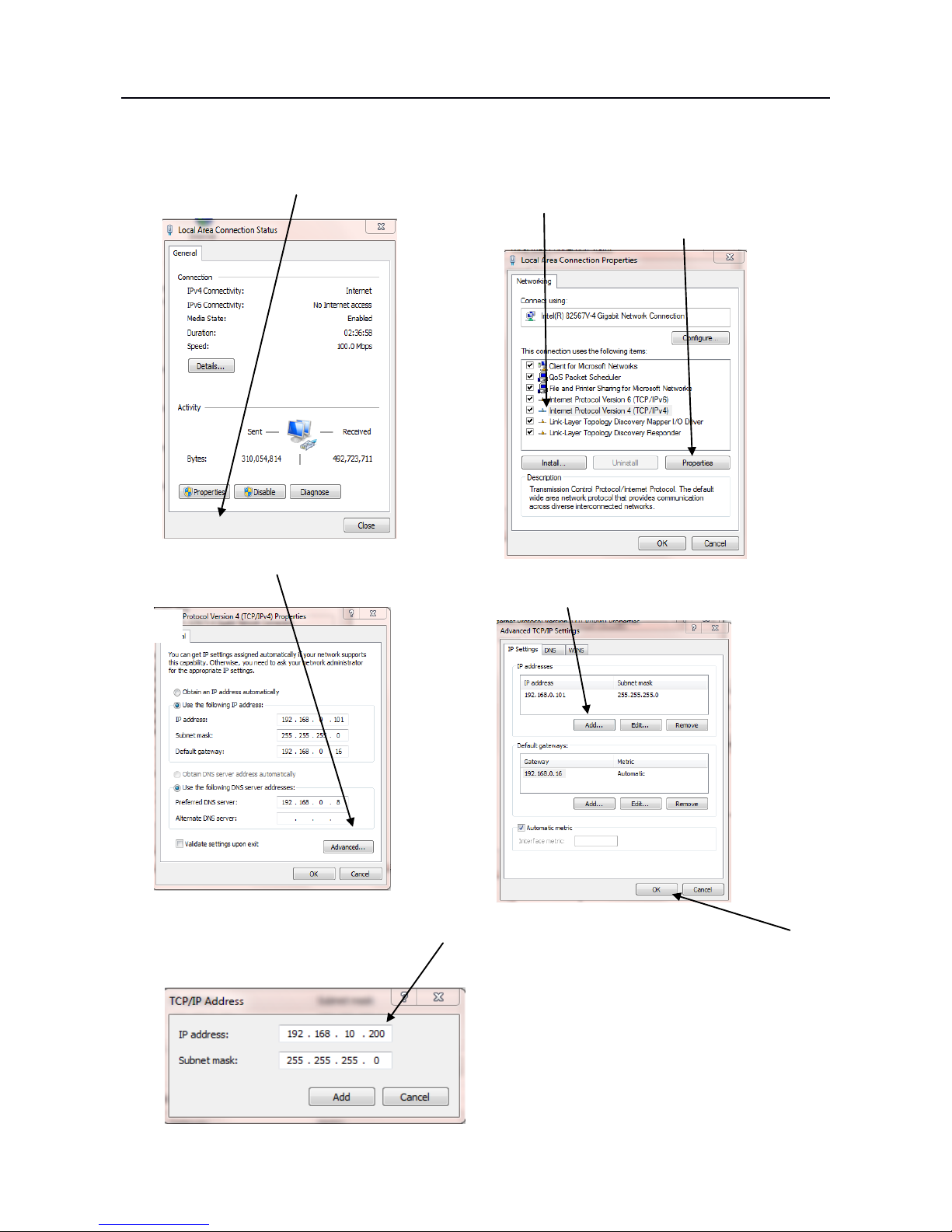
Step B Click on Properties Step C
Click on Internet Protocol Version 4 (TCP/IPV4)
and click Properties
Step D Click on Advanced
Step E Click Add
Step F Add an IP address in the range of the IP cameras but not the IP camera/s itself then click OK
This will allow ZipFinder to access not
only the 192.168.0.? addresses but also
the 192.168.10. ? addresses for changing
to 192.168.0.<n> addresses.
Also ZipFinder uses multicast protocol
for searching across subnets but firewalls
preclude this, so firewall may need to be
disabled during this process.
ZIP IPC USER MANUAL
8
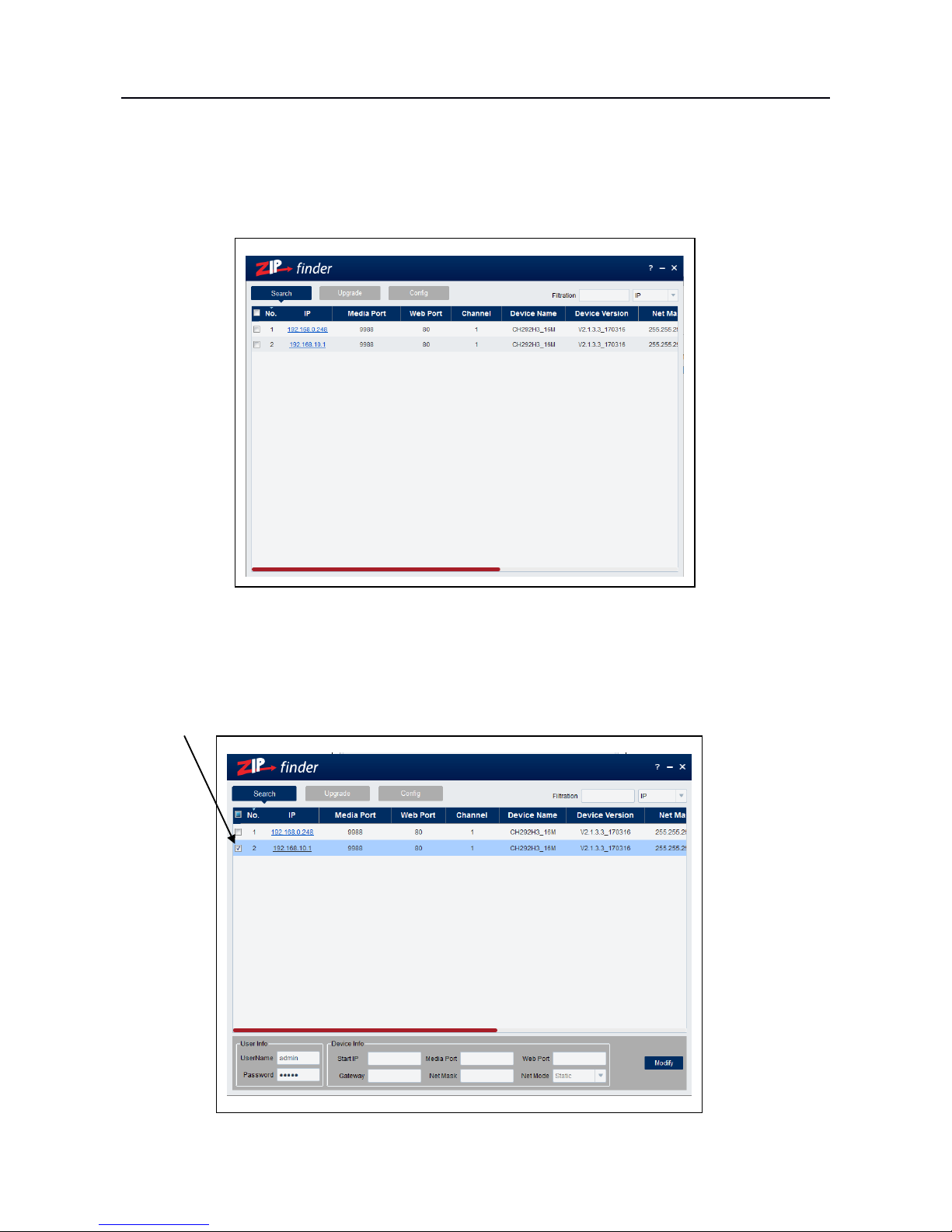
2. Run ZipFinder by double clicking icon. It will search and display any online IP address and its
IP address, port number, number of channels, device type and version, subnet mask, gateway, MAC
address and connection pattern.
3. You will see that the IP camera address 192.168.10.1 displays. To change the address, click on
the box to the left of the IP address.
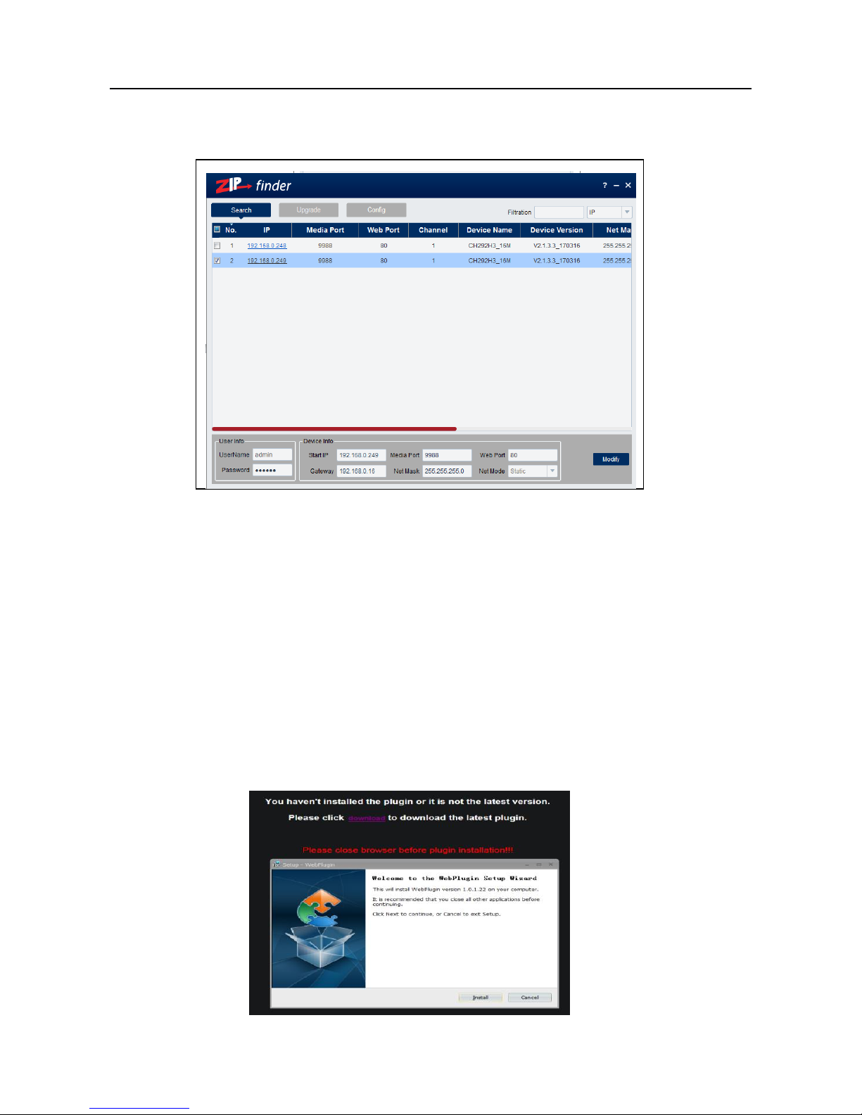
ZIP IPC USER MANUAL
9
4. You can now change the IP address by completing the section at the bottom of the screen and
click on Modify.See note below.
Note you need to enter the IP camera password that is 777777, the new IP address, Media Port 9988,
Web Port 80, Gateway (Local IP of Router) & Net Mask (Subnet Mask usually 255.255.255.0)
5. You can now add the next IP camera and follow the same procedure above.
6. Double click IP address to display login and enter password to view picture.
3.3 Installation of Controls and Login to System
Before using IE (Internet Explorer) browser to access the IP camera for the first time, related plugin components must be installed by following the procedure below:
Access IP address of the IP camera to automatically load the controls from it.
In a pop-up plug-in installation dialogue box, choose an installation option to perform the
installation process.
ZIP IPC USER MANUAL
10
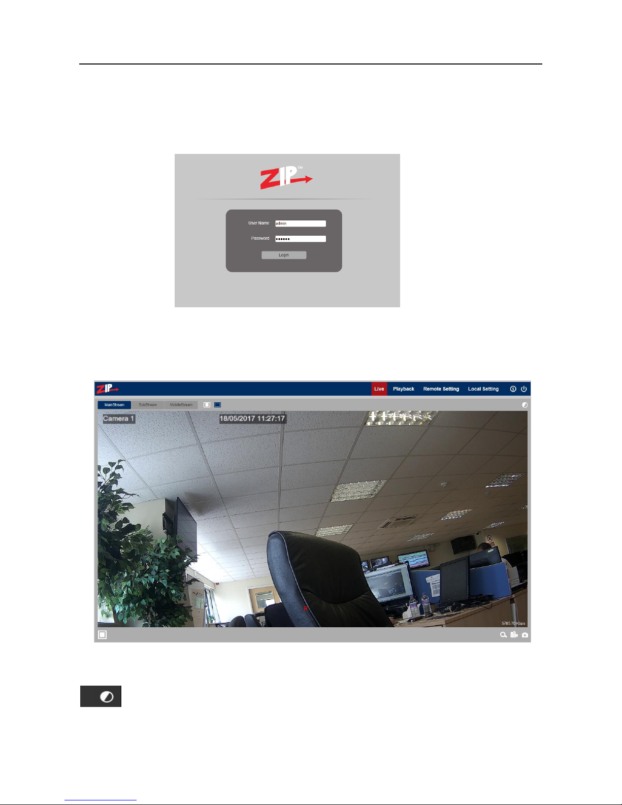
3.3.1 Preview
Open IE and enter the IP address of the camera e.g (http://192.168.0.248) to open a login box as
shown below:
In the login box you can choose a language for the IE client. Enter your user name (admin by
default) and password (777777) and then press OK to open a preview frame as shown below:
Some buttons in the preview frame are described below.
Colour setting button, for setting of colour, brightness, contrast, saturation and sharpness
of the picture.

ZIP IPC USER MANUAL
11
Reads the recorded files from SD card, and then plays back from browser
Access to Remote Setting menu for setting of various device parameters.
Help information (including current user, Web browser and plug-in versions),
and logout button for returning to the login page.
Preview frame ratio adjustment, toggling between Original and Widescreen.
Preview control buttons - Zoom-In/Out, Open Video, Capture and Sound
On/Off, Microphone arranged from the left to the right.
Resolution options
Note that if you experience lag time for picture refresh you may have a problem with network
resources, so selecting Substream or MobileStream may reduce this effect as they run at a lower
resolution and frame rate.
For setting snapshot, video file type and storage path.
See Section 5 – Local Setting for more details.

ZIP IPC USER MANUAL
12
3.3.2 Playback(optional function)
Click on Type All to select recorded file type, select the corresponding date and then click the
Search button. Note that the recording is made to an SD card in the camera. As the cards will only
hold limited recordings, the green line indicates the the current recorded period and this will change
as files are overwritten.
Click on date to playback
Select File Type -
Click Search
From left to right is Play/Pause, Stop, Frame playback (click one
frame at a time), Slow playback, Fast forward, Audio control
From left to right is Scale up, Video clips(need to setup in the progress
bar), Screenshot, Video download and Zoom

ZIP IPC USER MANUAL
13
4. Remote Setting
4.1 Camera
4.1.1 OSD Menu
Name: Name of the IP camera
Display Name: Choose Enable to display camera name
Display Time: Choose Enable to display time
Flicker Control: Choose 50Hz, 60Hz or disable it.
Transparency: Choose transparency of camera name and time in preview mode
(smaller value indicates higher transparency)
OSD: Text in red colour: You can locate the position of the camera name and time display on the
channel by dragging the information in the preview frame.
ZIP IPC USER MANUAL
14
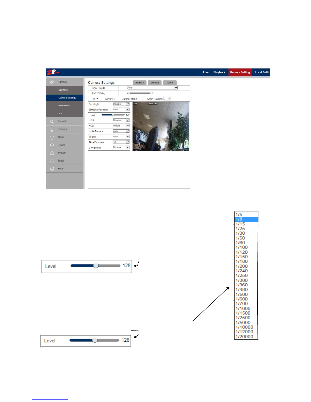
4.1.2 Camera Settings
Click on Camera Settings to open the following page:
IR-Cut Mode: Auto / Colour / Black and White
Delay: IR-cut switching delay 1 ~ 36 seconds (default = 2)
Image Display: Flip / Mirror / Corridor Mode / Angle rotation (0° or 180°)
Back Light: Disable or Enable Backlight Compensation
3D Noise reduction: Disable / Auto (default) / Manual /
WDR: Wide Dynamic Range Disable / Enable
AGC: Automatic Gain Control Off / Low / Middle / High
White Balance: Auto / Manual / Indoor
Shutter: Auto / Manual -
Defog Mode: Disable / Auto / Manual
Note: Below 2MP device , it doesn't support Corridor mode, Angle rotation or fog mode.
ZIP IPC USER MANUAL
15
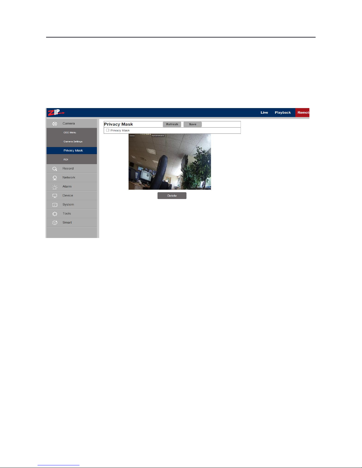
4.1.3 Privacy Mask
Click on Privacy Mask in Camera Menu to open the following page:
This option allows you to mask up to 4 areas at a time.
Procedure of setting Video Masking:
1. Tick the box marked Privacy Mask
2. Press down and hold the left mouse button and drag out an area for video masking (up to four
areas at one time)
3. Click on Save to enable the Privacy Masking area.
Removing a Privacy Mask area:
After clicking Refresh, choose a masked area by clicking in it and then click Remove and then click
Save.

ZIP IPC USER MANUAL
16
4.1.4 ROI (Region of Interest)
Click on ROI in Camera Menu to open the following page:
What is ROI (Region of Interest)
Region of Interest is where you want to select from 1 to 8 areas in a picture with improved frame
rate and quality, so allowing non-ROI areas to preview in lower frame rate and quality settings. The
benefit is lower storage requirements for data and better preview of areas most important to the user.
Procedure for setting ROI:
1. Choose an area of application
2. Press down and hold the left mouse button and draw out an ROI area (only one ROI can be set
for each area) but up to 8 areas can be selected.
3. Click on Save to apply the ROI area.
Stream Ttype: Choose from Main Bit Stream, Sub-Bit Stream or Cell Phone Stream which is the
lowest quality.
Region: 1 ~ 8. (Up to 8 ROI areas can be set in one bit stream).
ROI area: Enable or disable the ROI area
ROI Level: Set quality of the image in the area.
(Select from: Lowest, Lower, Low, Normal, Better, Best.)
Non-ROI Level: Set ROI level in one bit stream; larger value indicates higher-quality image in
ROI area (1~6 Levels)
Non-ROI Level: Sets frame rate out of the RIO area; smaller value indicates higher-quality image
in ROI area. Range of frame rate is in relation to video standard and resolution. (Note: Different
non-ROI frame rates may be allocated to different ROI areas, but the minimum value among them
is used as the frame rate to be applied for the non-ROI area on the preview frame. )

ZIP IPC USER MANUAL
17
4.2 Record
4.2.1 Record Settings
Click Record Settings in Record Menu
This function controls recording, pre-recording and the recording type (main stream or substream)
on an SDHC card facility incorporated in the camera. The card must be Class 10 or above. If the
camera does not have a Record and Playback menu option, then it will not have any SDHC card
hardware included. SDHC cards are not included in cameras by default that have record/playback
facilities, so reference must be made to product specifications at time of purchase.
Record: Enable / Disable Switches recording on or off to SDHC card if appropriate
PreRecord: Enable / Disable Captures a few seconds of recording using motion detection
Stream Type: Main Stream / Sub Stream Mainstream settings are higher resolution so use more
recording resources.

ZIP IPC USER MANUAL
18
4.2.2 Normal Schedule
The schedule for setting up record information covers one week from Sunday through to Saturday,
with each box representing a 30 minute recording time. For each day there are three lines covering
24x7 normal recording in green colour, motion recording in yellow colour and red in alarm mode
recording. The schedule is set for continuous recording in green for the default. White boxes depict
no recording.
Example: This shows weekend on alarm recording 00.00hrs – 0800hrs and 20.00 – 00.00hrs
and Monday to Friday 00.00hrs – 08.00hrs and 20.00hrs – 00.00hrs motion recording and
08.00hrs – 20.00hrs continuous recording.
ZIP IPC USER MANUAL
19
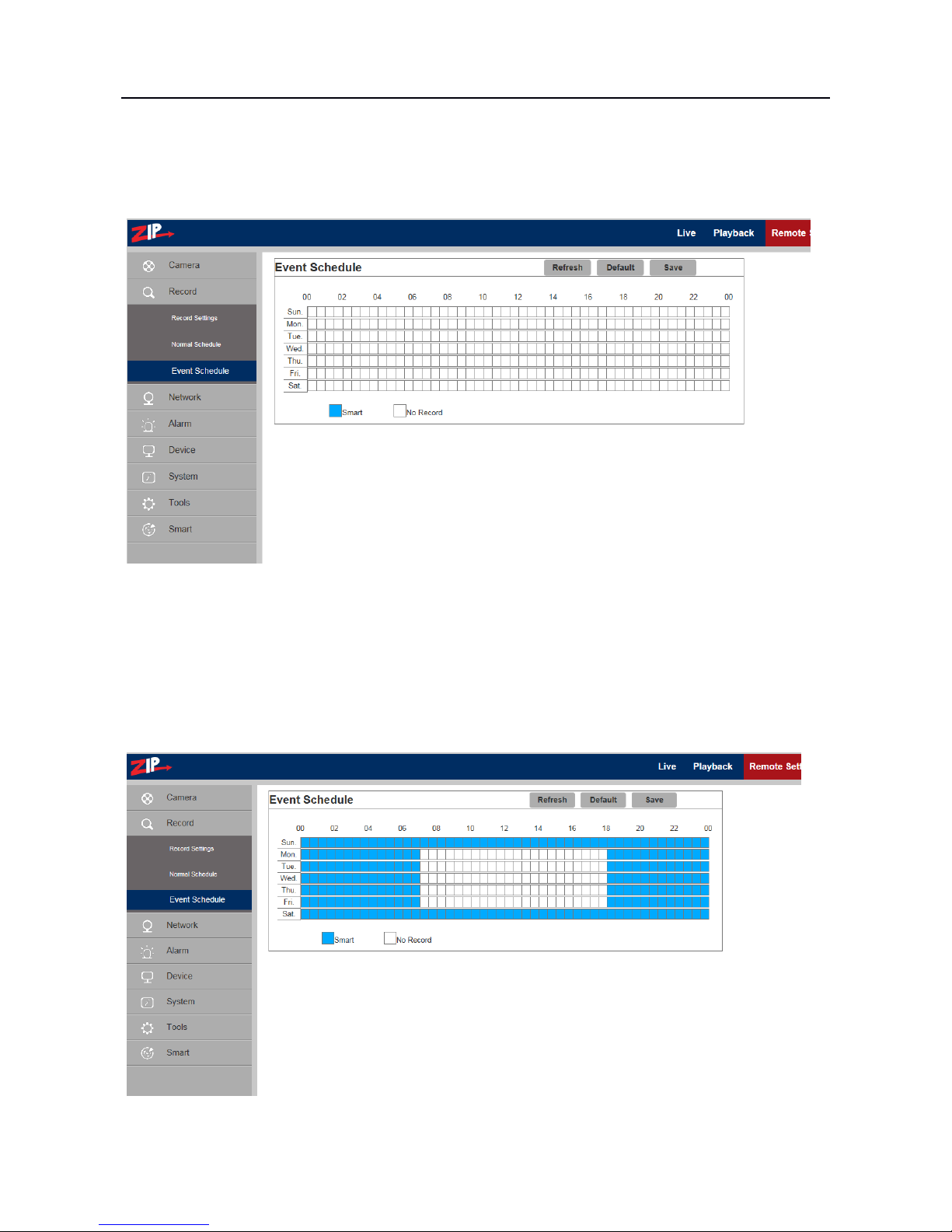
4.2.3 Event Schedule
The Event Schedule is for the SMART option only.
The Event schedule is for use with the SMART option which is documented in more detail later in
this manual. Again each box represents a 30 minute period. The box will display in blue when
clicked on for record and white for no record.
Example: This shows weekend on alarm recording all day and Monday to Friday 00.00hrs -
07.00hrs and 18.00hrs – 00.00hrs event recording.
ZIP IPC USER MANUAL
20
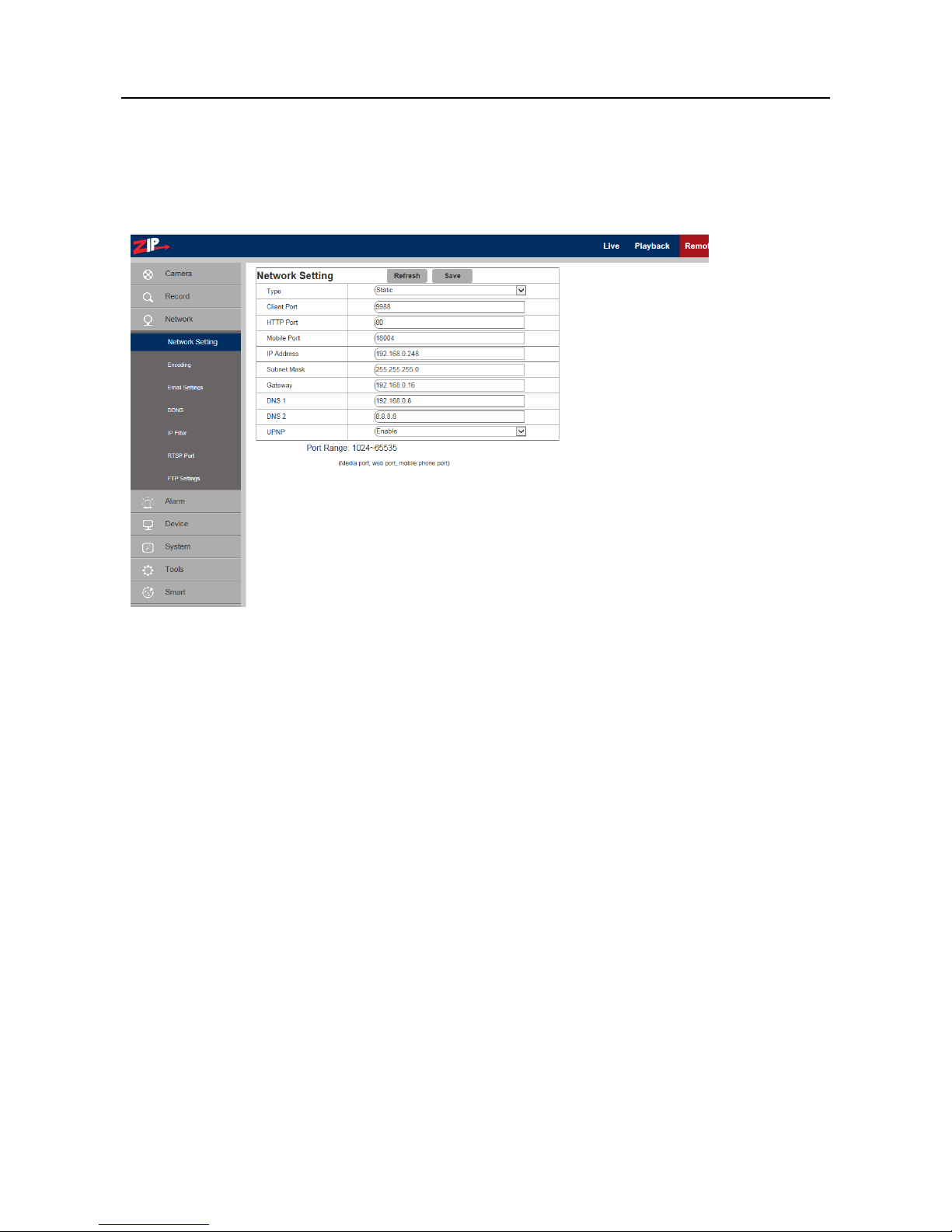
4.3 Network
Click on Network Parameters in Network to open the following page:
4.3.1 Network Parameters
Type: DHCP (Automatically Acquired), PPPOE, Static (Manually Configured – Default)
Client Port: Media (management) port Default = 9988
HTTP Port: Web port Default = 80
Mobile Port: Port for connection of mobile phone (Note: lower resolution quality)
IP Address: IP address (Default = 192.168.10.1)
Subnet Mask: Subnet Mask (Default = 255.255.255.0)
Gateway: Default gateway of the device
DNS 1: Preferred DNS Server DNS 2: Alternate DNS server
UPNP: Enable or disable UPNP function for the IP camera (Default = Enabled)
Note: To enable UPNP, the client/http/mobile phone port should be set to a value between 1024-
65535.
ZIP IPC USER MANUAL
21
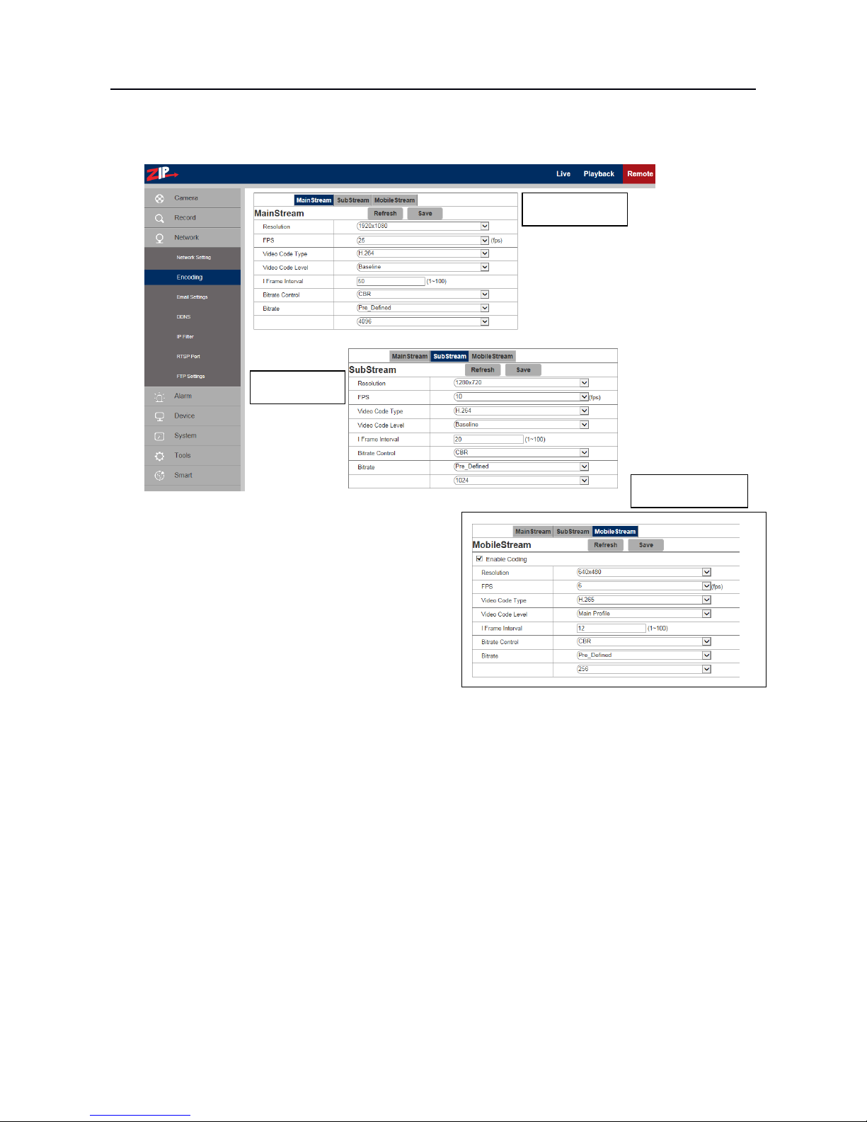
4.3.2 Encoding
Click on Encoding in Network Menu to open the following page:
Resolution: Set resolutions respectively for encoding:
The resolutions for Main Stream are 2592×1520, 2048 x 1520, 2304 x 1296, 1920 x 1080.
The resolutions for Sub Stream are 1280 x 720, 640 x 480, 320 x 240.
The resolutions for Mobile Stream are 640 x 480, 320×240.
Note: The highest resolution for Main Stream 3MP cameras is 2048*1520 (frame rate at 30 fps).
The highest resolution for Main Stream 4MP cameras is 2592*1520 (frame rate of 20 fps).
The highest resolution for Main Stream 2MP cameras is 1920*1080 (frame rate of 30 fps).
FPS (Frame rate per sec): When refresh rate is 50Hz, the maximum available frame rate is 25 fps.
When refresh rate is 60Hz, the maximum available frame rate is 30 fps.
Video Code Type: Set video encoding compression to H265 or H264 for bit stream option.
Note: Zip DVRs require H264 compression but mobile phone app will use H265.
Bit Stream Options:
Main Stream / Sub Stream / Mobile Stream
You can set resolution, frame rate, video
encoding, encoding level, audio, I frame interval,
variable frame rate and bit stream size respectively
for main stream, sub-stream and mobile stream
Main Stream
Sub Stream
Mobile Stream

ZIP IPC USER MANUAL
22
Audio: Enable audio for each bit stream.
I frame interval: The I frame interval is the number of frames before a new reference frame is
created. You start with encoding a full frame and then holding changes to that frame on the next
frame until the count is reached. The default setting is 50 for mainstream, 20 for substream and 12
for mobile stream. Note that lag time issues may occur when too many reference frames are set or
alternatively when too many changes occur across each non reference frame. Therefore individual
tests will provide the most accurate setting.
Bitrate control: Set constant (CBR) or variable bitrate (VBR). Although VBR is generally the best
option regarding network bandwidth use, tests show that overall CBR is the recommended setting.
Bit stream: Set bit stream value by choosing fixed value or customising it.
Note: Range of Main bit stream is 256-8192 Default = 4096
Range of Sub-bit stream is 128-4096 Default = 1024
Range of Mobile bit steam is 8-1536 Default = 256
Video encoding and encoding level are unavailable in setting page of IP camera of 2MP Series.
4.3.3 E-Mail Configuration
If the IP camera has Email options, then this can be used, but it is only applicable to this camera
channel. The NVR or DVR used, may have a global Email facility that avoids replication for each
channel, so this option may not be the best option to use.
Test Email Settings

ZIP IPC USER MANUAL
23
Email Setup: Email service setting - used with the alarm function to upload images to mail server.
Enable Email: Enable or disable Email function.
SSL:ON/OFF Security setting used by Email service provider
SMTP Port: The default port number is 25 - Email server port used by Email service provider
SMTP Server: Enter the address of mail server - SMTP port used by Email service provider
Sender: Address of sending Email account
Sender Password: Password of sending Email account
Receiver: Address of receiving Email account
Interval: Time interval for sending mail (1 minute, 3 minutes, 5 minutes, 10 minutes) .
Test Email: Click it to test whether the mailbox is configured properly by sending a test mail to
the recipient's mailbox.
4.3.4 DDNS Configuration
This option allows the camera to use a third party DDNS service to determine the current IP address.
This does not use the IPPOSTCODE service.
6.4 DDNS Configuration
Click on DDNS Configuration in Network Parameter menu to open the following page:
ation: Dynamic DNS configuration - used with server for access from an extranet.
DDNS: Enable or disable it.
Server: Select DYNDNS or NO-IP
Host Name: Enter the name of active server
User Name: Name of the user
Password: Password of the user Use the Test DDNS button to test service
ZIP IPC USER MANUAL
24
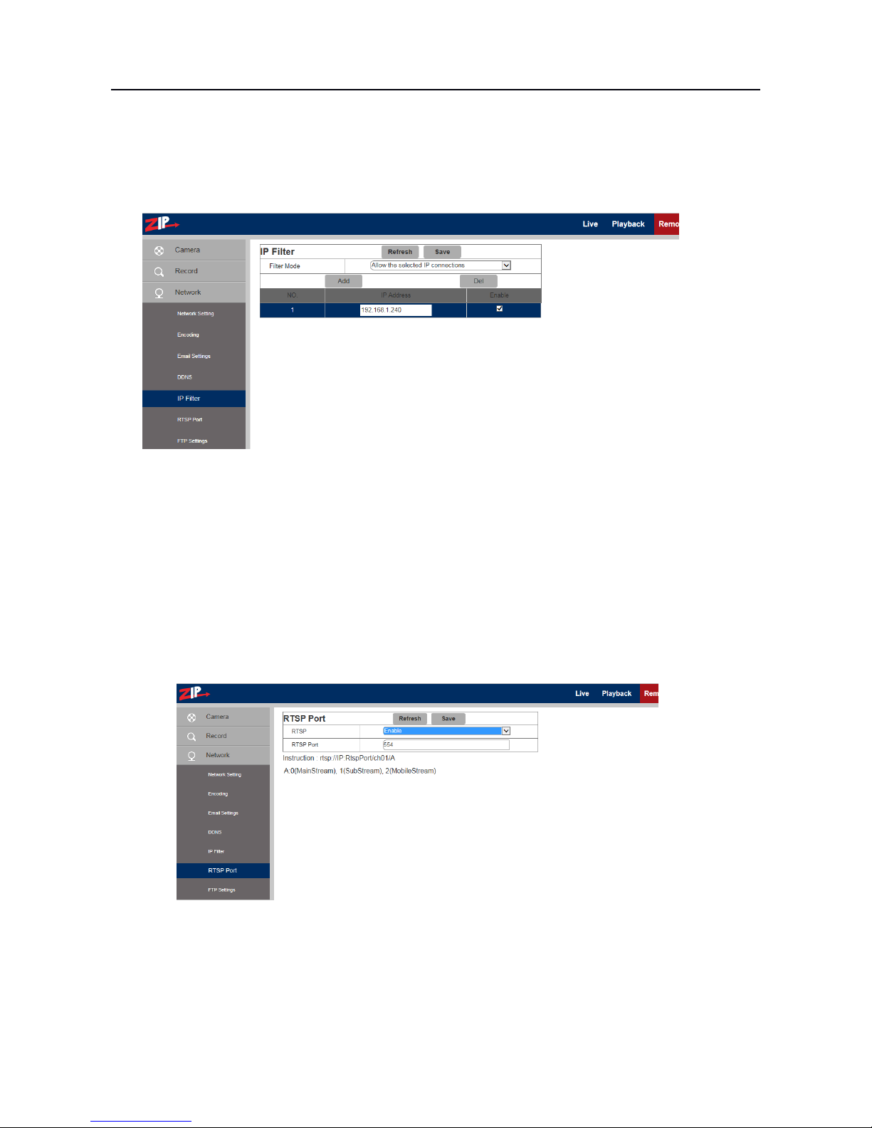
4.3.5 IP Filtering
Select IP Filter to allow, restrict or block IP connections.
Filter mode: Three modes are available - Allow all IP connections,
Allow the selected IP connections,
Block the selected IP connections.
Add: Add any allowed or blocked IP addresses
Delete: Delete any IP address no longer required
4.3.6 RTSP
Select RTSP to open the Realtime Streaming Port. This port must be open to view video streaming.
RTSP: Enable or disable RTSP. RTSP is enabled by default.
RTSP Port: The RTSP port is 554 by default. The NVR/DVR RTSP port is 1240 by default.
On a remote connection these ports must be unique on the same network. This port can be changed
ZIP IPC USER MANUAL
25
to another value between 1024 and 65535. Modification of the port number will restart the system.
Special Operation Instructions:
For IP cameras in 3MP/4MP/5MP/8MP series you can call the RTSP stream using e.g VCL player
by entering
rtsp://<User>:<Password of IP camera>@<IP Address>:<Port No.>/ch01/<x>
Example: rtsp://admin:777777@192.168.0.248:554/ch01/0
Where …. User:Password = User and password set in IP camera
IP address = IP address of IP camera
Port No. = RTSP port set in IP camera
ch01 = number of channels (set to 01 as default for IP camera)
x = 0 (mainstream), 1(substream), 2 (mobile phone stream)
For IP cameras in 2MP series you can call the RTSP stream using e.g VCL player by entering
rtsp://<User>:<Password of IP camera>@<IP Address>:<Port No.>/ <x>
Example: rtsp://admin:777777@192.168.0.248:554/ 0
IP address = IP address of IP camera
Port No. = RTSP port set in IP camera
x = 0 (mainstream), 1(substream), 2 (mobile phone stream)
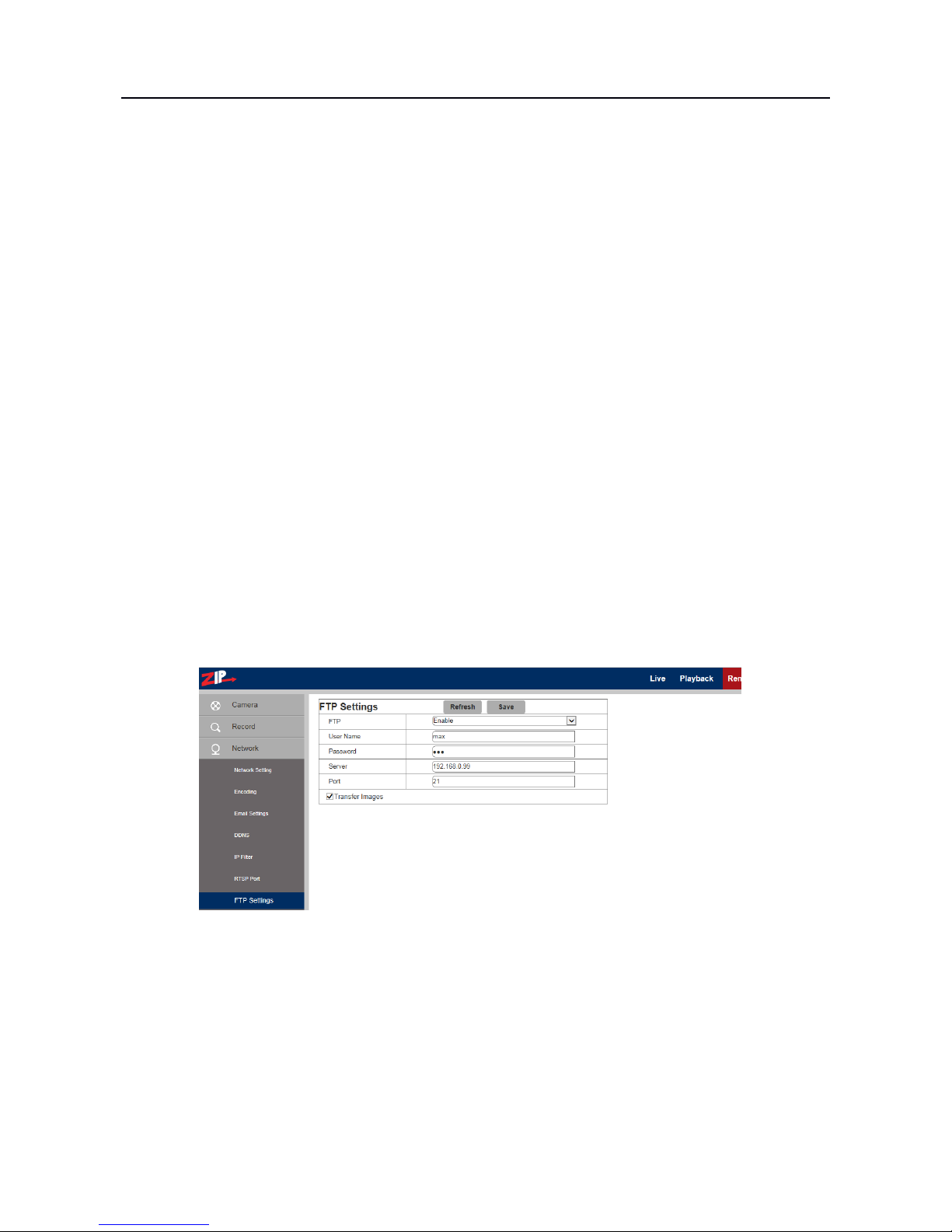
4.3.7 FTP
Click on FTP menu to open the following page. You will need an FTP server to use this.
Note if FTP is switched on then the Email service will not run.
FTP: FTP service setting - used with alarm function to upload images or videos to an FTP server.
FTP: Enable or disable it.
User Name: The user name for access to FTP service
Password: The password for access to FTP service
FTP Server: Enter the IP address of FTP server.
Port: FTP service port number; the default number is 21.
Transmit Images: Click on box to transfer images.

ZIP IPC USER MANUAL
26
4.4 Alarm
4.4.1 Motion Detection
Click on Motion to open Motion Detection menu.
Procedure for setting Motion Detection
1. Check Enable Motion Detection.
2. Press down and hold the left mouse button and drag mouse over area for motion detection.
3. Set the sensitivity for mobile detection (1 ~ 8 and the larger the value the higher the sensitivity).
4. Used with SMTP to enable mail delivery.
5. Click on Save to apply the settings.
(Note: When any object moves within the target area, a letter "M" in green colour will be displayed
on the preview frame)

ZIP IPC USER MANUAL
27
4.4.2 Alarm Settings
Click on Alarm Settings in Alarm menu:
Alarm Input: Select NO (Normally Open), NC (Normally Closed) or Off
Send Email: Click on Send Email box to send email
Note if FTP is switched on then the Email service will not run.
Enable Record: Click on Enable Record for recording to SD card
Post Recording: Select additional recording time (5, 10, 20, 30 seconds)
4.4.3 Lens Covered
Click on Lens Covered in Alarm Parameter menu.
Enable: Tick Enable (checked by default) to activate Sensitivity Level and Email Link options.
Sensitivity: Set security level for lens blocking (1~8). The higher value the higher the security level.
EMail Link: Disabled by default. After enabling may be used with SMTP to enable Email.
ZIP IPC USER MANUAL
28
4.5 Device
This menu includes optional functions i.e SD Card, Audio Setting and Log information.
(Note that these menu items may be suppressed it they are not supported on the camera).
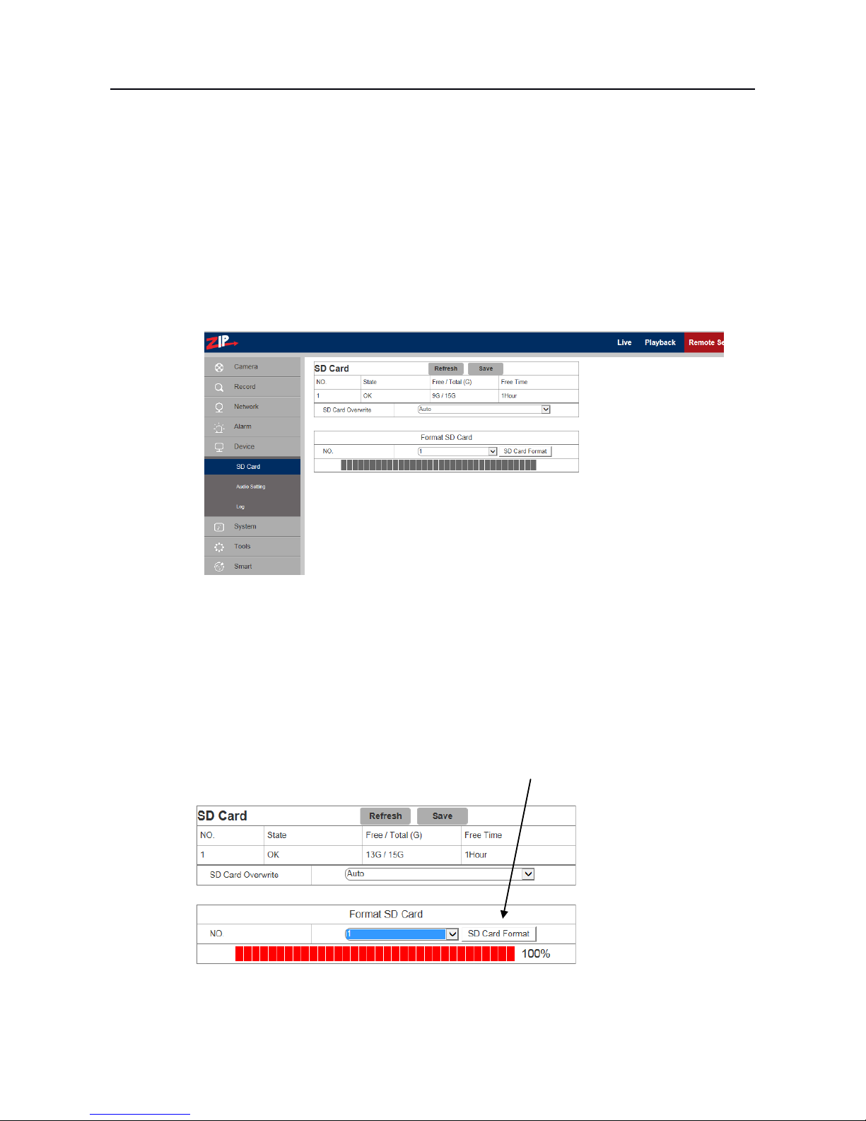
4.5.1 SD Card(optional function – option available if menu is displayed)
(If the camera menu displays SD card function this does not imply SD card is fitted. Always refer to
specifications).
Click SD Card in the Device menu.
Insert SD card in camera and system will auto detect the available capacity and total capacity of the
SD card and give an approximate remaining record time.
SD Card Overwrite: When the Auto option (default) is set, the SD card will overwrite old data
when full, but when set to Close, the SD card will stop recording when full.
SD Card Format: If you click on the SD Card Format box the SD card will be formatted and the
display below the box will confirm when it has completed the request.
ZIP IPC USER MANUAL
29
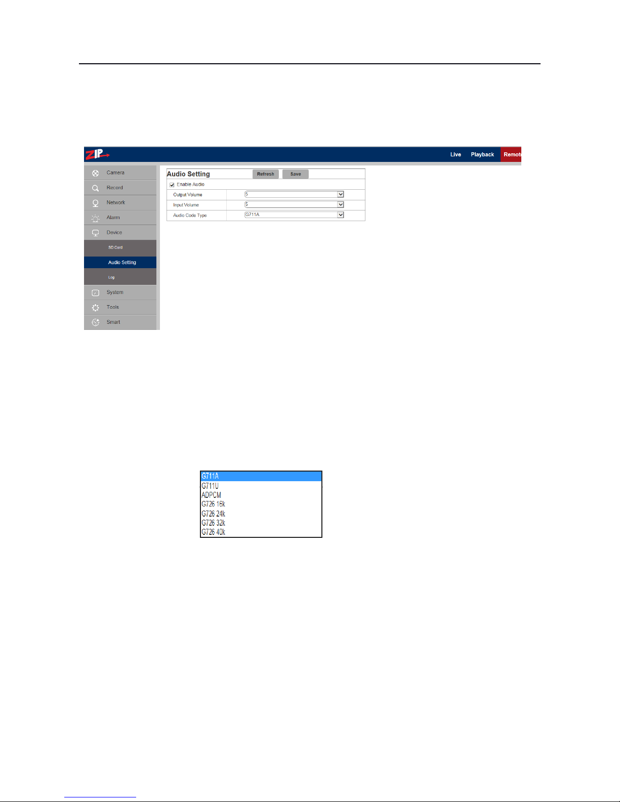
4.5.2 Audio (optional function – available if audio lead on camera)
Click on Audio in Device menu. Click the Enable Audio box to expand menu options.
Procedure for setting Audio
Enable Audio: Check that Enable Audio has been ticked.
Output Volume: Set Output Volume (ranging 0~10).
Input Volume: Set Input Volume (ranging 0~10).
Audio Code Type:
Select codec required
(Note: For application of audio function, the audio option in Network > Encoding menu is
automatically enabled).
ZIP IPC USER MANUAL
30
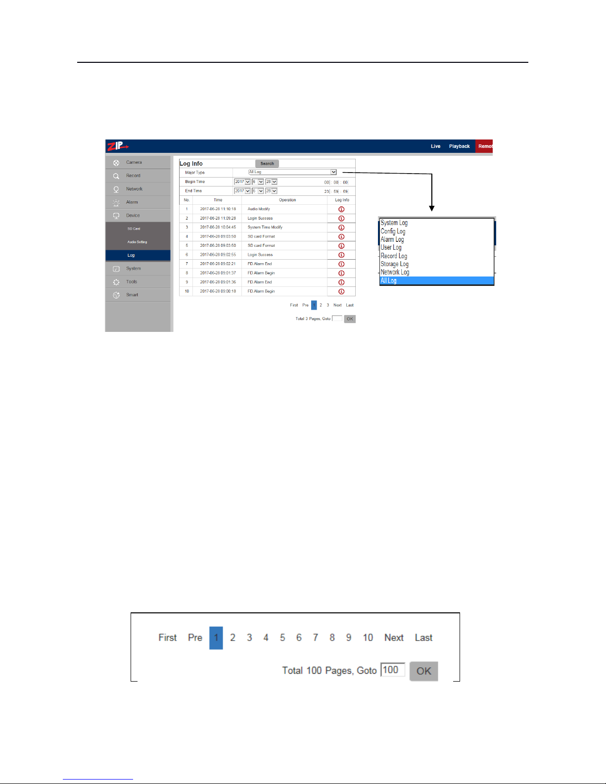
4.5.3 Log
Click on Log in Device menu.
Major Type: There are eight types of logging information held and include - System Log, Config
Log, Alarm Log, User Log, Record Log, Storage Log, Network Log and All Log.
Each page of the log can display up to 10 records and up to 100 pages can be held at anyone time.
Therefore a total of 1000 log records can be held. Select Log type required.
Begin Time: Click on Year, Month and Day to select search start date.
Click on Hour, Minute and Seconds to select search start time.
End Time: Click on Year, Month and Day to select search end date.
Click on Hour, Minute and Seconds to select search end time.
Search: Click to retrieve and display related logs. Up to 100 pages of 10 records per page can be
held in the camera and each time an additional log entry is made, it is added to the log or if the log
is full, it overwrites the oldest entry.
There are some further options available when the search has completed:
Either use page number, first, previous, next or last or enter page number in GoTo box.
ZIP IPC USER MANUAL
31
4.6 System
System parameters include Date and Time Information, User Setup Information, Camera System
Information and Smart Analysis Reports.
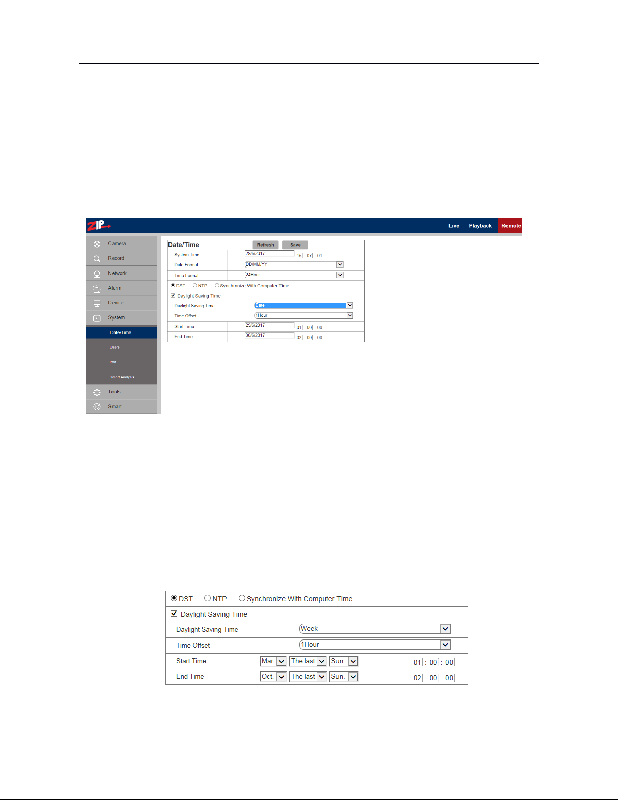
4.6.1 Date and Time Information
Click on Date/Time in System Parameters menu.
The device time, system time, date format and time format contained in the Date and Time
information can be manually set and saved.
System Time: Click in date box and select correct date in calendar. Click on hour, minute and
second column to set correct time
Date Format: Select from DD/MM/YY, YY-MM-DD or MM/DD/YY
Time Format: Select 24 Hour or 12 Hour
There are three automatic time correction functions provided in this camera.
DST (Daylight Saving Time), NTP (Network Time Protocol) and Synchronize With Computer
Time
DST: Check Daylight Savings Time (DST) option to enable DST correction. The device will
correct the time, based on the time deviation changes in March and October each year.

ZIP IPC USER MANUAL
32
Synchronise with Computer Time:
Check Synchronize With Computer Time option and the camera will use the PC as a time server to
correct the date and time.
NTP:
Check Enable NTP option, input the address of time
server and choose a time zone and then save the setting. The
system will correct time in accordance with the time server.
There are three time servers that you can select from.
ZIP IPC USER MANUAL
33
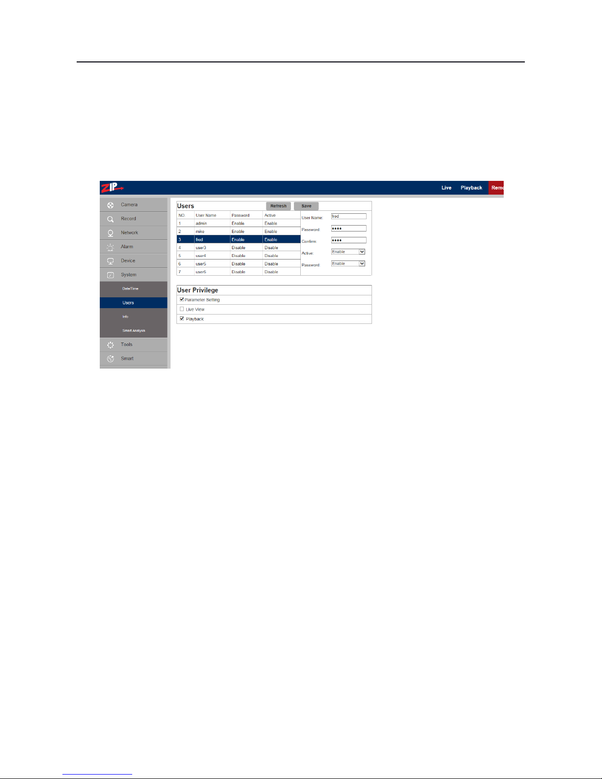
4.6.2 Users
Click on Users in System Parameters menu. This allows you to set user access authority and login
user and password settings. By default there is only one administrator (admin) and has full
permissions and controls up to six users. The six users can be restricted from making parameter
settings, live viewing and reviewing playback.
admin: There is only one admin user and they have full user privileges. The admin user can set up
to six additional users with unique usernames and passwords. The User Privilege box does not
display for the admin user.
user1 ~ user6: Up to six users can be setup with up to 12 character username and password.
Active: Enable or disable the user.
Password: Enable or disable password.
User Privilege
Parameter Setting: Tick option to allow camera menu access and changes
Live View: Tick option to allow live viewing of video stream
Playback: Tick option to allow access to playback feature
Save: Save settings

ZIP IPC USER MANUAL
34
4.6.3 Information
Click on Info in System menu.
This menu describes the system information held on the camera including the device name, serial
number, Hardware Version, Software Version, I.E Client version, MAC address and AF version.
You can use the P2P QR code for mobile phone parameter setup.
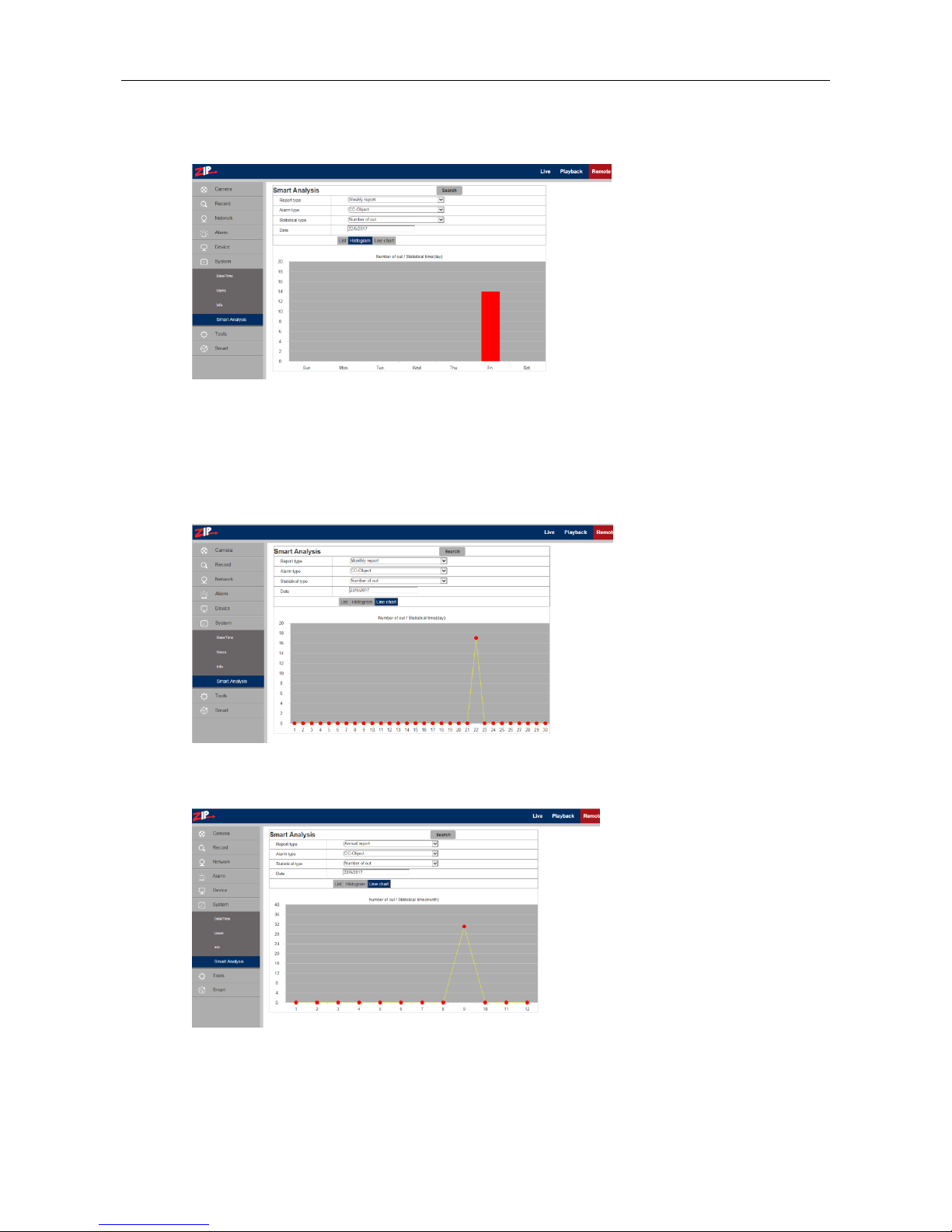
4.6.4 Smart Analysis (CC)
The Smart Analysis menu is used to display the Smart analysis results in various formats for Cross
Counting. Refer to the menu section 4.8.6 Cross Counting (CC) for initial setup and analysis
options.

ZIP IPC USER MANUAL
35
4.7 Tools
This menu includes Firmware Update, Load Default and Reboot options.
4.7.1 Firmware Update
Click on Firmware Update in Tools menu.
Scan: Click on scan button to locate Zip folder storing firmware version
Update will be unavailable if the update files do not match the target device.
4.7.2 Load Default
Click on Load Default in Tools menu.
There are three default options. Select individual menus, simple group option or all menus.
1. Click on boxes to select menus to be defaulted.
2. Click on Simple option to select Camera, Device, System, Tools and Smart.
3. Click on All to select all menus with an option to exclude Network settings if required.
Save: Defaults menus selected.

ZIP IPC USER MANUAL
36
4.7.3 Reboot
Click on Reboot in Tools menu
Click on Auto Reboot down arrow key and select Enable, then click Reboot.

ZIP IPC USER MANUAL
37
4.8 Smart
4.8.1 Perimeter Intrusion
Click Perimeter Intrusion in the Smart menu.
The purpose of this option is to record footage, send an Email and log information, when crossing
from A to B, from B to A or in both directions within a defined area, mapped on the display picture.
Switch: Enable/Disable option
Latch Time: The external output alarm alarm time can be set to 5, 10, 20 and 30 seconds.
Post Recording:When the alarm is triggered this option sets the time period for recording after
the trigger expires. The time period is 5, 10, 20 or 30 seconds. The recording is made to the storage
device used by the camera, so the playback facility is dependent on storage space available.
Sensitive:Sensitive level is in the range of 1 ~ 4 with a default of 2. If the level is set higher then
movement is more easily detected however false activation is also more likely. So always best to
start with default setting.
Scene:Select either indoor or outdoor.
Enable I/O Out:Triggers alarm if ticked.
Send Email:If alarm triggers, it sends the Email notification. The Email setup needs to be set in
Remote Setting – Network – Email.
Record:Set to enable record function.
Rule Number:Up to 4 different rules may be set by selecting rule numbers 1 ~ 4.
Rule Type:Setting up a rule. A->B means can detect A to B direction moving, B->A means can
detect B to A direction moving, A ←→B means can detect two directions moving.

ZIP IPC USER MANUAL
38
4.8.2 Line Crossing Detection(LCD)
The purpose of this option is to record footage, send an Email and log information, when crossing a
line from A to B, from B to A or in both directions as mapped on the display picture. Up to 4 rules
can be set.
Switch: Enable/Disable option
Latch Time: The external output alarm latch time can be set to 5, 10, 20 and 30 seconds.
Post Recording:When the alarm is triggered this option sets the time period for recording after
the trigger expires. The time period is 5, 10, 20 or 30 seconds. The recording is made to the storage
device used by the camera, so the playback facility is dependent on storage space available.
Sensitive:Sensitive level is in the range of 1 ~ 4 with a default of 2. If the level is set higher then
movement is more easily detected however false activation is also more likely. So always best to
start with default setting.
Scene:Select either indoor or outdoor.
Enable I/O Out:Triggers alarm if ticked.
Send Email:If alarm triggers, it sends the Email notification. The Email setup needs to be set in
Remote Setting – Network – Email.
Record:Set to enable record function.
Rule Number:Up to 4 different rules may be set by selecting rule numbers 1 ~ 4.
Rule Type:Setting up a rule. A->B means can detect A to B direction moving, B->A means can
detect B to A direction moving, A ←→B means can detect two directions moving.

ZIP IPC USER MANUAL
39
4.8.3 Stationary Object Detection
The purpose of this option is to draw a box in an area of the picture to detect when an object is
removed or added and to trigger an alarm, send an Email and record when this happens.
Switch:Enable or Disable option
Latch Time: The external output alarm latch time can be set to 5, 10, 20 and 30 seconds.
Post Recording:When the alarm is triggered this option sets the time period for recording after
the trigger expires. The time period is 5, 10, 20 or 30 seconds. The recording is made to the storage
device used by the camera, so the playback facility is dependent on storage space available.
Sensitive:Sensitive level is in the range of 1 ~ 4 with a default of 2. If the level is set higher then
movement is more easily detected however false activation is also more likely. So always best to
start with default setting.
Scene:Select either indoor or outdoor.
Enable I/O Out:Triggers alarm if ticked.
Send Email:If alarm triggers, it sends the Email notification. The Email setup needs to be set in
Remote Setting – Network – Email.
Record:Set to enable record function.
Rule Number:Up to 4 different rules may be set by selecting rule numbers 1 ~ 4.
Rule Type:There are three rule types, Legacy, Lost or Both. Legacy refers to items that are
present in the picture, Lost refers to items no longer in the picture and Both refers to both options.
Special Note: When this function is enabled, you will need to wait between 30 seconds and one
minute for the search to complete, during which the function is locked. Also you cannot save the
function when Pedestrian Detection, Live Crossing Detection or Stationary Object Detection are
enabled.

ZIP IPC USER MANUAL
40
4.8.4 Pedestrian Detection (PD)
Purpose of Function
The purpose of this option is to draw a box in an area of the picture, so that when a moving object
enters the detection area, the program extracts the moving foreground to analyse whether there is a
human involved. The box must be a convex quadrilateral e.g and not
and must contain the whole body.
Trigger Conditions:
1) Minimum area for targeting movement:
The minimum target areas that can be detected respectively under the detection levels from small
to large, account for about 4.0%-7.4% of the whole picture size. To aid sizing of the detection area
box you will see two red boxes in top left hand corner of the picture. These boxes vary in size when
clicking on the Target size parameter either Small, medium or Large. The minimum target area will
be between the area size between the two red boxes.
2) The pedestrians must be within the scope of the drawn detection area.
3) The pedestrians must be moving.
Switch:Click to Enable or Disable option
Latch Time: The external output alarm latch time can be set to 5, 10, 20 or 30 seconds.
Post Recording: After an alarm is triggered, the optional record time for continuous video
recording can be set to 5, 10, 20 or 30 seconds.
Target Size: The parameter scope for detection level includes Small, Medium and Large, with a
default value of Medium. The Small parameter is used for a detection area further away that will
require a smaller detection box. The Large target size will generally require a larger detection box
because the subject will be closer.
Scene: Indoor only.
Enable I/O Out: whether the triggered alarm has I/O output.
Send Email: If an alarm is triggered, an Email will be sent as a notice, with corresponding Emails
set in Remote Setting-Network-Email.

ZIP IPC USER MANUAL
41
Record: whether a video is recorded.
Rule Number: Only one rule can be set
Rule Switch: Enable / Disable
Rule Type: Normal only.
How Pedestrian Detection Works:
Below is the instructions for setting up Pedestrian Detection.
When an alarm is triggered, the moving target will be surrounded by a coloured rectangular box and
a letter is shown just under the preview picture. The letter for Pedestrian Detection is “S” for Smart
option and the colour is red for record or green for no record. If options for standard continuous
recording or motion have also been set then you may also see a letter “R” for normal continuous
recording or “M” for motion recording and again the colour will be red for record or green for no
record. If the I/O alarm option has been set then a letter “I” will be displayed, and again this will be
in red for record or green for no record.
Note these colour codes do no relate to the colour codes used in the Record Schedule/Playback
Screen.
Method for setting up:
1. Enter the Pedestrian Detection interface and set Enable.
2. Click the mouse button in the area where you need to draw the target pedestrian detection box
and choose the Rule Number without drawing the pedestrian detection area yet.
3. Enable rule.
4. Now using a mouse create a convex quadrilateral box (See comments about Purpose of Function
above). Create this yellow box by dragging the cursor point and clicking on 4 points, which will be
connected and form an enclosed area. In one corner of the area created you will see a small red
square. Now click on Save. The save will only be actioned if the shape is a convex quadrilateral
shape. To modify the shape of the drawn pedestrian detection area you can only select the small
number box of the area and turn the yellow area into a red area. You can now click on one of the
red circle points of the area to adjust the shape.
5. To delete the pedestrian detection area, you can only select its number box and click Delete,
while ‘Delete All’ means to delete all the existing pedestrian detection areas if your camera
provides more than one pedestrian detection area.
Note:
1) The set detection area must be accessible for pedestrians to avoid an invalid detection and the
detection area should cover the whole body in the picture to avoid the failure to trigger an alarm.

ZIP IPC USER MANUAL
42
4.8.5 Face Detection (FD)
Purpose of Function
The purpose of this option is to draw a box in an area of the picture, so that when a person enters
the detection area, the program extracts the moving foreground to analyse whether a front view of a
person’s face is involved.
NOTE: The channel must be in mainstream mode in order to display the trace boxes when in
preview mode.
Trigger Conditions:
1) Minimum area for targeting movement:
The minimum target areas that can be detected respectively under the detection levels from small
to large, account for about 0.44% ~ 0.72% of the whole picture size. To aid sizing of the detection
area box you will see two red boxes in top left hand corner of the picture. These boxes vary in size
when clicking on the Target size parameter either Small, medium or Large. The minimum target
area will be between the area size of the two red boxes.
2) The human faces must be within the scope of the drawn detection area.
3) The human face must be a moving front view.
Display results:
When an alarm is triggered, the moving target will be surrounded by a green rectangular box. In the
middle of the picture just below this box you will see the letter ‘S’ displayed for Smart option
running. This letter will be red in colour when the camera is recording and green when no video is
recorded.
Parameters:
Switch:Click to Enable or Disable option
Latch Time: The external output alarm latch time can be set to 5, 10, 20 or 30 seconds.

ZIP IPC USER MANUAL
43
Post Recording: After an alarm is triggered, the optional record time for continuous video
recording can be set to 5, 10, 20 or 30 seconds.
Target Size: The parameter scope for detection level includes Small, Medium and Large, with a
default value of Medium. The Small parameter is used for a detection area further away that will
require a smaller detection box. The Large target size will generally require a larger detection box
because the subject will be closer.
Scene: Indoor only.
Enable I/O Out: whether the triggered alarm has I/O output.
Send Email: If an alarm is triggered, an Email will be sent as a notice, with corresponding Emails
set in Remote Setting-Network-Email.
Record: whether a video is recorded.
Rule Number: Only one rule can be set
Rule Switch: Enable / Disable
Rule Type: Normal only.
Method for setting up:
1. Enter the Face Detection interface and set Enable.
2. Click the mouse button in the area where you need to draw the target face detection box and
choose the Rule Number without drawing the pedestrian detection area yet.
3. Enable rule.
4. Now using a mouse create a face detection area. Create a convex quadrilateral yellow box by
dragging the cursor point and clicking on 4 points, which will be connected and form an enclosed
area. In one corner of the area created you will see a small red square. Now click on Save. The save
will only be actioned if the shape is a convex quadrilateral shape. To modify the shape of the drawn
face detection area you can only select the small number box of the area and turn the yellow area
into a red area. You can now click on one of the red circle points of the area to adjust the shape.
5. To delete the face detection area, you can only select its number box and click Delete, while
‘Delete All’ means to delete all the existing face detection areas if your camera provides more than
one pedestrian detection area.
Note:
1) The set detection area must be able to view a full front view of a face to avoid an invalid
detection and the detection area must cover the whole face in the picture to avoid the failure to
trigger an alarm.

4.8.6 Cross Counting (CC)
Purpose of Function
The purpose of this option is to calculate the number of pedestrian movements or objects crossing a
line either from A to B or from B to A and produce analytical statistics over a time period. The
option to produce the statistics is found in the System Menu - Smart Analysis.
Display Results
This option provides statistical information that is used by the Smart Analysis menu in the System
Menu. There are 3 options - List, Histogram or Line Chart.
List option - Example for a Daily Report
This option provides a statistical report for a Daily, Monthly or Annual Extract for Object or
Pedestrian movement moving from A to B or from B to A. Further reports and available in
Histogram or Line Chart format. Note that using Pedestrian requires the complete body crossing the
line whereas the Object settings detects all objects and partial bodies.
45
Histogram option - Example for a Weekly Report
This option provides a histogram report for a Daily, Monthly or Annual Extract for Object or
Pedestrian movement moving from A to B or from B to A.
Line Chart option - Example for a Monthly Report
Line Chart option - Example for an Annual Report
The two examples above show line chart reports that can be extracted for a Daily, Monthly or
Annual Extract for Object or Pedestrian movement moving from A to B or from B to A.

46
Parameters:
Switch:Click to Enable or Disable option
Latch Time: The external output alarm latch time can be set to 5, 10, 20 or 30 seconds.
Post Recording: After an alarm is triggered, the optional record time for continuous video
recording can be set to 5, 10, 20 or 30 seconds.
Sensitive: Sensitive level is in the range of 1 ~ 4 with a default of 2. If the level is set higher then
movement is more easily detected however false activation is also more likely. So always best to
start with default setting.
Scene:Indoor only.
Enable I/O Out:Triggers alarm if ticked.
Send Email:If alarm triggers, it sends the Email notification. The Email setup needs to be set in
Remote Setting – Network – Email.
Record:Set to enable record function.
Rule Number:This parameter cannot be changed and only allows 1 rule.
Rule Switch: Enable / Disable
Rule Type:Pedestrian or Object. Note that using Pedestrian requires the complete body crossing
the line whereas the Object settings detects all objects and partial bodies.

47
5. Local Setting
5.1 Local Setting Options
For taking manual recordings, downloads and video captures to your PC hard drive when in live
mode, you need to create the respective folders on your PC first. You can use the default folder
names shown below or amend them to new path names. You can also use File Type to create Qzip
format or AVI format files and set duration of recording or downloading in minutes using the
Interval option.
5.1.1 Record Path
To change the record path first ensure the folder exists on the PC, then click on the dots at the end
of Record Path setting and select the new path to be used.
5.1.2 Download Path
To change the download path first ensure the folder exists on the PC, then click on the dots at the
end of the Download Path setting and select the new path to be used.
5.1.3 Snapshot (Capture) Path
To change the capture path first ensure the folder exists on the PC, then click on the dots at the end
of the Capture Path setting and select the new path to be used.
5.1.4 File Type
Select Vzip for H264/H265 or AVI. The Qzip files will require the Vzip Player whereas the AVI
file can be played using Windows Media Player etc. Just double click the file to auto detect the
correct player.
5.1.5 Interval
The interval time is the maximum record time to the SD card in the camera.

48
 Loading...