


Chapter
Chapter
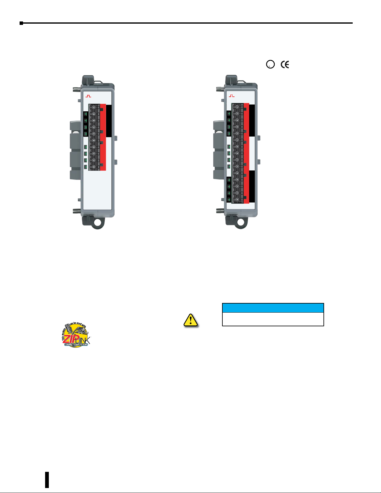
BRX Digital i/O EXpansiOn
Chapter
MODulEs
7
7
7
In This Chapter...
Overview ....................................................................................................................................................... 7-2
Module Types ...............................................................................................................................................7-3
Wiring Termination Options ........................................................................................................................ 7-5
General Specifications .................................................................................................................................. 7-8
Module Installation ..................................................................................................................................... 7-8
BX-xxNF3 Sinking/Sourcing 3–5 VDC Input ................................................................................................7-9
BX-xxND3 Sinking/Sourcing 12–24 VDC Input .........................................................................................7-10
BX-xxNB 12–24 VAC Input .........................................................................................................................7-13
BX-xxNA 120–240 VAC Input .....................................................................................................................7-15
BX-08SIM Simulator Input..........................................................................................................................7-17
BX-xxTD1 Sinking 12–24 VDC Output ....................................................................................................... 7-18
BX-xxTD2 Sourcing 12–24 VDC Output ..................................................................................................... 7-21
BX-16TF2 Sourcing 3–5 VDC Output .........................................................................................................7-24
BX-xxTR Relay Output ................................................................................................................................ 7-25
BX-xxTRZ Relay Output .............................................................................................................................. 7-27
BX-05TRS Relay Output .............................................................................................................................. 7-28
BX-05TRS-1 Relay Output ........................................................................................................................... 7-29
BX-xxTA 120–240 VAC Output ................................................................................................................... 7-30
BX-08CD3R Combination DC Input/Relay Output .................................................................................... 7-32
BX-xxCD3D1 Combination DC Input/Sinking DC Output ........................................................................ 7-34
BX-xxCD3D2 Combination DC Input/Sourcing DC Output ...................................................................... 7-37
BX-16CF3F2 Combination DC Input/DC Sourcing Output........................................................................7-40

Chapter 7: BRX Digital I/O Expansion Modules
Overview
One key feature of the BRX platform is its ability to expand its capability to fit your application solution.
One of the ways the BRX platform can do this is by using expansion modules that conveniently “Snap-on” to
the side of any BRX MPU. Once the expansion module has snapped in place it is automatically added to the
project and instantly adds additional I/O and features to the MPU with little to no additional setup required.
NOTE: To learn more about adding expansion units to the project, go to “Installing the Expansion I/O Modules” in
Chapter 1.
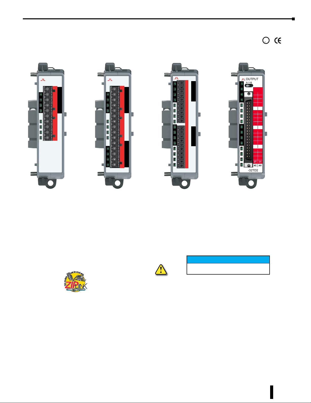
The digital expansion modules give you the ability to add additional discrete I/O as needed and are identified
as an input module, output module or combination input/output module. On the front panel of the digital
I/O expansion modules a color scheme and a symbol are used to denote the module type.
Most modules are available in 5, 8, 12, 16 or 32 point variations consisting of sink/source DC inputs/
outputs, AC inputs/outputs, relay outputs and combination modules.
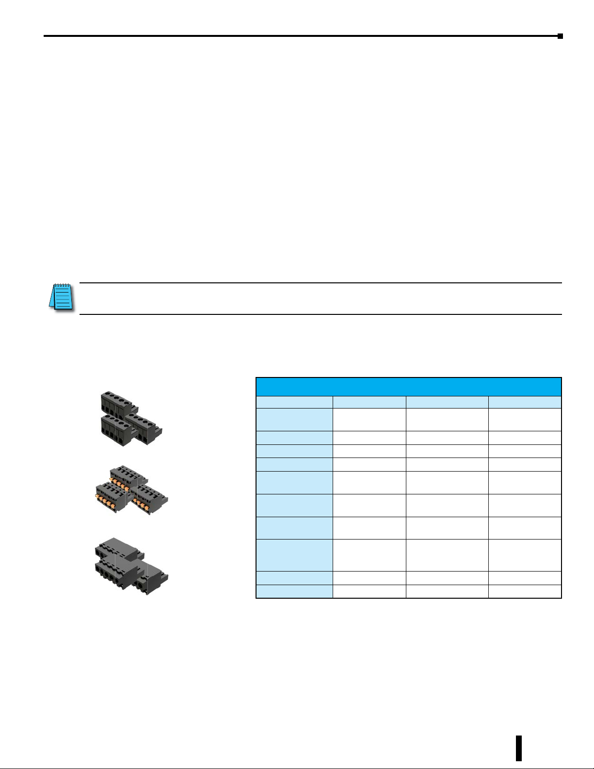
The modules ship without wiring terminal blocks. This allows you to select the termination style that best
fits your application. There are several wiring options available, including screw terminal connectors, spring
clamp terminal connectors and pre-wired ZIPLink cable solutions.
More detailed information about the digital expansion modules along with specifications and wiring diagrams
follow in this chapter.
NOTE: When using relay expansion modules, adding 32 or more relay points requires you to perform a power
budget calculation. See Appendix C for more information.
7-2
BRX User Manual, 4th Edition, Rev. F

UPDATED
Module Types
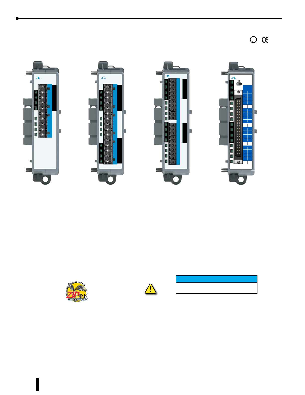
Discrete Input Modules
Thirteen (13) discrete input modules are available in various DC and AC voltage ranges.
INPUT
X
BX-16ND3
Discrete input module faceplates have a blue terminal bar and symbol ⎍ for easy distinction
1C
from other module types. Listed in the table below are the five different types of input modules
0
1
available.
2
3
2C
4
5
6
7
3C
8
9
10
11
4C
12
13
14
15
Blue Label
for Input
Chapter 7: BRX Digital I/O Expansion Modules
Discrete Input Modules
Identifier Type 8-Point 12-Point 16-Point 32-Point
NF3
ND3
NB 24VAC BX-08NB BX-12NB BX-16NB N/A
NA 120VAC BX-08NA BX-12NA BX-16NA N/A
SIM Simulator BX-08SIM N/A N/A N/A
3–5 VDC
Sink/Source
12–24 VDC
Sink/Source
BX-08NF3 N/A BX-16NF3 N/A
BX-08ND3 BX-12ND3 BX-16ND3 BX-32ND3
Discrete Output Modules
Eighteen (18) discrete output modules are available in DC sinking, DC sourcing, AC voltage
OUTPUT
Y
BX-16TD1
and Relay type outputs. Discrete output module faceplates have a red terminal bar and symbol
1C
⎍ for easy distinction from other module types. Listed in the table below are the five different
0
1
types of output modules available.
2
3
2C
4
5
6
7
3C
8
9
10
11
4C
12
13
14
15
Red Label
for Output
Discrete Output Modules
Identifier Type 5-Point 8-Point 12-Point 16-Point 32-Point
TD1
TD2
TF2
TR
TRZ
TRS
TA
12–24 VDC
Sinking
12–24 VDC
Sourcing
3–5 VDC
Sourcing
Relay
Form A (SPST)
Relay
Form A (SPST),
no surge suppression
Relay
Form C (SPDT)
120–240 VAC
Triac
N/A BX-08TD1 BX-12TD1 BX-16TD1 BX-32TD1
N/A BX-08TD2 BX-12TD2 BX-16TD2 BX-32TD2
N/A N/A N/A BX-16TF2 N/A
N/A BX-08TR BX-12TR BX-16TR N/A
N/A BX-08TRZ N/A BX-16TRZ N/A
BX-05TRS,
BX-05TRS-1
N/A N/A N/A N/A
N/A BX-08TA BX-12TA N/A N/A
BRX User Manual, 4th Edition, Rev. F
7-3

Chapter 7: BRX Digital I/O Expansion Modules
Module Types, Continued
Discrete Combo Input/Output Modules
Six (6) discrete input/output combo modules are available with DC sink/source inputs and
sink/source/relay outputs. The Input/Output faceplate terminal bar is in blue and red, with both the blue ⎍
and red ⎍ symbols to make it easy to distinguish between inputs and outputs and from other module types.
IN/OUT
X
Y
BX-16CD3D1
1C
0
1
2
3
2C
4
5
6
7
1C
0
1
2
3
2C
4
5
6
7
UPDATED
Blue and Red
Label
for Input/Output
Discrete Combo Input/Output Type
Identifier Identifier Input Type Output Type 8-Point 12-Point 16-Point
D1
CD3
CF3 F2
D2
12–24 VDC
Sink/Source
R
3–5 VDC
Sink/Source
12–24 VDC
Sinking
12–24 VDC
Sourcing
Relay
Form A (SPST)
3–5 VDC
Sourcing
BX-12CD3D1 BX-16CD3D1
N/A
BX-12CD3D2 BX-16CD3D2
BX-08CD3R N/A N/A
N/A N/A BX-16CF3F2
7-4
BRX User Manual, 4th Edition, Rev. F
Wiring Termination Options
The BRX digital expansion modules ship without wiring terminals blocks. This allows you to select the
termination style that best fits your application. There are several wiring options available, including
removable screw terminal connectors, removable spring clamp terminal connectors and pre-wired ZIPLink
cable solutions.
Terminal Block Connectors
The terminal block connectors are provided in kits of multiple connectors that are easily ordered as a single
part number. There are 2 different types of kits to choose from; one kit for the five, eight and 12-point discrete
modules and one kit for the 16-point discrete modules. The five, eight and 12-point module kit includes
(3) 5-pin 5mm connectors. The 8-point modules will use only 2 of the 5-pin connectors, one (1) will not be
used. The 5 and 12-point modules will use all three connectors. The 16-point module kits include (2) 10-pin
3.81 mm connectors.
NOTE: 32-point modules are not compatible with terminal block connectors and require ZIPLink cables.
Chapter 7: BRX Digital I/O Expansion Modules
Terminal block kit part numbers and connector specifications are listed in the following tables.
Terminal Block Connectors, 5-Point, 8-Point & 12-Point Discrete Modules
Terminal Block Specifications 5, 8 & 12-point Type
Kit Part Number BX-RTB08 BX-RTB08-1 BX-RTB08-2
BX-RTB08 Kit
BX-RTB08-1 Kit
BX-RTB08-2 Kit
Connector Type
Wire Exit 180 degree 180 degree 180 degree
Pitch 5.0 mm 5.0 mm 5.0 mm
Screw Size M2.5 N/A M2.5
Screw Torque
Recommended
Screwdriver
Blade Width
Wire Gauge
(Single Wire)
Wire Gauge
(Dual Wire)
Wire Strip Length 0.3 in (7.5 mm) 0.37 in (9.5 mm) 0.3 in (7.5 mm)
Equiv. Dinkle P/N 5ESDV-05P-BK 5ESDSR-05P-BK 5ESDF-05P-BK
Screw Type -
90 degree
< 3.98 lb·in
(0.45 N·m)
3.5 mm 3.5 mm 3.5 mm
28–12 AWG 28–14 AWG 28–12 AWG
28–16 AWG
Spring Clamp Type -
180 degree
N/A
28–16 AWG
(Dual Wire Ferrule
Required)
Screw Type -
180 degree
< 3.98 lb·in
(0.45 N·m)
28–16 AWG
BRX User Manual, 4th Edition, Rev. F
7-5

Chapter 7: BRX Digital I/O Expansion Modules
Terminal Block Connectors, 16-Point Discrete Modules
Terminal Block Specifications 16-point
Part Number BX-RTB10 BX-RTB10-1 BX-RTB10-2
Connector Type
BX-RTB10 Kit
BX-RTB10-1 Kit
BX-RTB10-2 Kit
Wire Exit 180 degree 180 degree 180 degree
Pitch 3.81 mm 3.81 mm 3.81 mm
Screw Size M2 N/A M2
Screw Torque
Recommended
Screwdriver
Blade Width
Wire Gauge
(Single Wire)
Wire Gauge
(Dual Wire)
Wire Strip Length 0.24 in (6mm) 0.35 in (9mm) 0.26 in (6.5 mm)
Equiv. Dinkle P/N EC381V-10P-BK ESC381V-10-BK EC381F-10P-BK
UPDATED
Screw Type
90 degree
<1.77 lb·in
(0.2 N·m)
2.5 mm 2.5 mm 2.5 mm
28–16 AWG 26–18 AWG 30–16 AWG
28–18 AWG
Spring Clamp Type
180 degree
N/A
30–20 AWG
(Dual Wire Ferrule Required)
Screw Type
180 degree
<1.77 lb·in
(0.2 N·m)
30–18 AWG
ZIPLink Wiring System
BRX digital expansion modules can be quickly connected to convenient ZIPLink remote terminal blocks for
ease of wiring remote I/O devices. Your ZIPLink selection is dependent on the number of expansion module
terminal points. The following tables list the connector options.
8-Point BRX Digital Expansion Module ZIPLink Selector
Expansion
Module Part No.
BX-08ND3
BX-08NF3
BX-08NA
BX-08NB
BX-08TD1
BX-08TD2
BX-08TR
BX-08TRZ
BX-08TA
BX-08CD3R
* Select the cable length: Blank = 0.5 m, -1 = 1.0 m, -2 = 2.0 m.
Available pigtail cables: ZL-BXEM-CBL10-1P = 1.0 m, ZL-BXEM-CBL10-2P = 2.0 m.
ZIPLink Module
Feedthrough
ZIPLink Module Part
No.
ZL-RTB20,
(standard)
-OR-
ZL-RTB20-1
(compact)
Qty
Needed
1
ZIPLink Cable
Part No.*
ZL-BXEM-CBL10
ZL-BXEM-CBL10-1
ZL-BXEM-CBL10-2
Qty
Needed
1
7-6
BRX User Manual, 4th Edition, Rev. F
UPDATED
Chapter 7: BRX Digital I/O Expansion Modules
12 & 5-Point BRX Digital Expansion Module ZIPLink Selector
Expansion
Module Part No.
BX-12ND3
BX-12NA
BX-12NB
BX-12TD1
BX-12TD2
BX-12TR
BX-05TRS
BX-12TA
BX-12CD3D1
BX-12CD3D2
* Select the cable length: Blank = 0.5 m, -1 = 1.0 m, -2 = 2.0 m.
Available pigtail cables: ZL-BXEM-CBL15-1P = 1.0 m, ZL-BXEM-CBL15-2P = 2.0 m.
ZIPLink Module
Feedthrough
ZIPLink Module Part
No.
ZL-RTB20 (standard)
-OR-
ZL-RTB20-1 (compact)
Qty
Needed
1
16-Point BRX Digital Expansion Module ZIPLink Selector
Expansion
Module Part No.
BX-16ND3
BX-16NF3 Feedthrough
BX-16NA
BX-16NB
BX-16TD1
BX-16TD2
BX-16TF2
BX-16TR
BX-16TRZ
BX-16CD3D1
BX-16CD3D2
BX-16CF3F2
* Select the cable length: Blank = 0.5 m, -1 = 1.0 m, -2 = 2.0 m.
Available pigtail cables: ZL-BXEM-CBL20-1P = 1.0 m, ZL-BXEM-CBL20-2P = 2.0 m.
ZIPLink Module
Sensor ZL-LTB16-24-1 1
Feedthrough
Feedthrough
Feedthrough
Relay (Sourcing)
Relay (Sinking)
Feedthrough
Feedthrough
ZIPLink Module Part
No.
ZL-RTB20 (standard)
-OR-
ZL-RTB20-1 (compact)
ZL-RRL16-24-1
ZL-RRL16W-24-1
ZL-RRL16F-24-1
ZL-RRL16HDF-24-1
ZL-RRL16-24-2
ZL-RRL16W-24-2
ZL-RRL16F-24-2
ZL-RRL16HDF-24-2
ZL-RTB20 (standard)
-OR-
ZL-RTB20-1 (compact)
Qty
Needed
1
1
1
1
ZIPLink Cable
Part No.*
ZL-BXEM-CBL15
ZL-BXEM-CBL15-1
ZL-BXEM-CBL15-2
ZIPLink Cable
Part No.*
ZL-BXEM-CBL20
ZL-BXEM-CBL20-1
ZL-BXEM-CBL20-2
Qty
Needed
1
Qty
Needed
1
32-Point BRX Digital Expansion Module ZIPLink Selector
Expansion
Module Part No.
BX-32ND3
BX-32TD2
* Select the cable length: Blank = 0.5 m, -1 = 1.0 m, -2 = 2.0 m.
Available pigtail cables: ZL-D24-CBL20-1P = 1.0 m, ZL-D24-CBL20-2P = 2.0 m.
Suffix -X indicates 45° cable connector angle. Non -X indicates 180° cable connector angle.
BRX User Manual, 4th Edition, Rev. F
ZIPLink Module
Sensor ZL-LTB32-24-1 1
Feedthrough
Feedthrough
ZIPLink Module Part
No.
ZL-RTB40 (standard)
-OR-
ZL-RTB40-1 (compact)
Qty
Needed
1BX-32TD1
ZIPLink Cable
Part No.*
ZL-D24-CBL40
ZL-D24-CBL40-1
ZL-D24-CBL40-2
Qty
Needed
1
7-7
Chapter 7: BRX Digital I/O Expansion Modules
To remove, depress
General Specifications
All BRX digital expansion modules have the same general specifications listed in the table below.
General Specifications
Operating
Temperature
Storage Temperature -20° to 85°C (-4° to 185°F)
Humidity 5 to 95% (non-condensing)
Environmental Air No corrosive gases permitted
Vibration IEC60068-2–6 (Test Fc)
Shock IEC60068-2-27 (Test Ea)
Enclosure Type Open Equipment
Noise Immunity NEMA ICS3-304
EU Directive See the “EU Directive” topic in the Help File
Agency Approvals
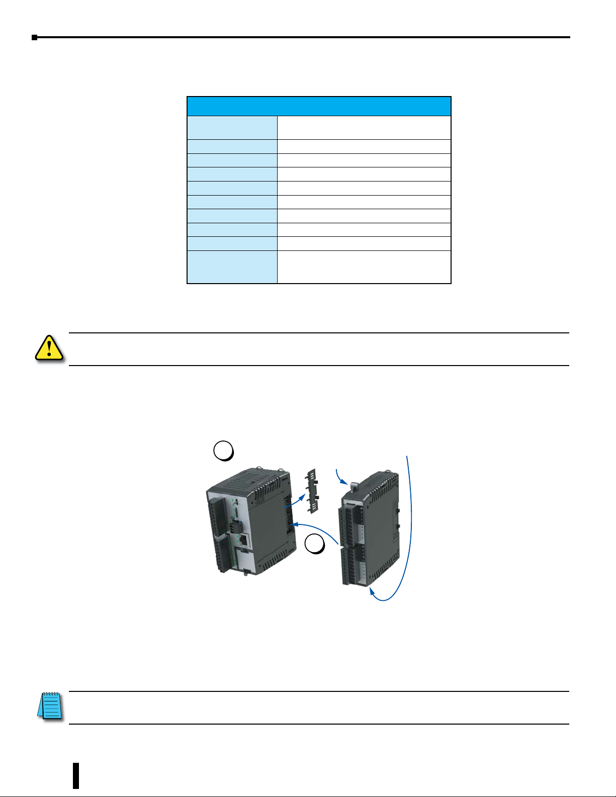
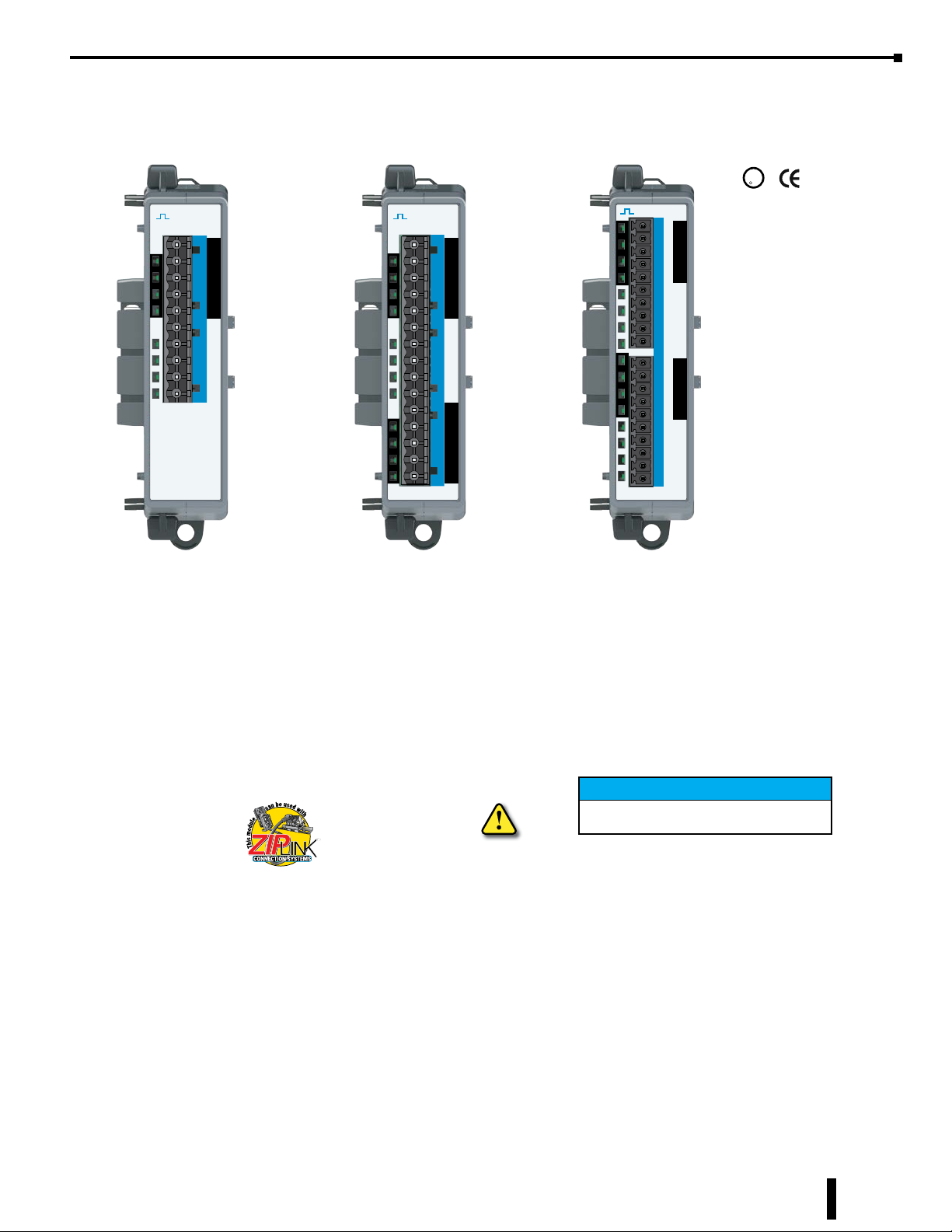
Module Installation
0° to 60°C (32° to 140°F)
UL 61010-2 - UL File # E185989 Canada and
USA
CE Compliant EN61131-2
WARNING: Do not apply field power until the following steps are completed. The BRX expansion modules are
NOT hot swappable.
To install an expansion module, remove the connector cover on the right side of the MPU or expansion
module to which the new module is to be connected. Align the expansion connectors, insert the module until
you hear a “click”, indicating the module expansion connectors have engaged.
To Install, remove
1
Connector Cover
PWR
RUN
RUN
TERM
STOP
ERR
TX
RX
LNK
ACT
Align
expansion
connectors, insert,
and listen for “click”
as the lock engages
To remove an expansion module locate the two disengagement levers. One is located at the top of the of the
disengagement plungers
at top and bottom
of module
2
expansion module and a second one at the bottom of the expansion module. Firmly drawing the top and
bottom disengagement levers forward at the same time will release the locking mechanism and disengage the
unit from the system.
7-8
NOTE: Allow a minimum of 45mm (1.75 in) to the right of MPU chassis or any subsequent expansion modules for
mounting and dismounting of the modules.
BRX User Manual, 4th Edition, Rev. F

C
US
X
Sourcing Input
All Expansion units with 3.3-5 VDC inputs – NF3
Sinking Input
X
UPDATED
Chapter 7: BRX Digital I/O Expansion Modules
BX-xxNF3 Sinking/Sourcing 3–5 VDC Input
INPUT
BX-08NF3
U
L
R
1C
0
1
X
2
3
2C
4
5
X
6
7
BX-08NF3
Input Module
8-pt, 3–5 VDC
Sink/Source
Terminal Blocks or
ZIPLink Cable
Sold Separately
We recommend using prewired ZIPLink
cables and connection modules.
If you wish to hand-wire your module,
a removable terminal block is available.
See Wiring Termination Selection in this
chapter for all options.
INPUT
1C
0
1
2
3
2C
4
5
6
7
X
3C
8
9
10
11
4C
12
13
14
15
BX-16NF3
BX-16NF3
Input Module
16-pt, 3–5 VDC
Sink/Source
Terminal Blocks or
ZIPLink Cable
Sold Separately
Discrete Input Specifications
BX-08NF3 BX-16NF3
Input Type Sink/Source
Inputs per Module 8 16
2 (4
Commons
Nominal Voltage Range 3–5 VDC
Input Voltage Range 2–6 VDC
Maximum Voltage 6VDC
Input Impedance 870Ω @ 5VDC
Input Current (typical) 6mA @ 5VDC
Maximum Input Current 8mA @ 6VDC
Heat Dissipation 0.6 W Max 1.1 W Max
ON Voltage Level > 2.0 VDC
OFF Voltage Level < 0.8 VDC
Minimum ON Current 1.2 mA (2V required-guarantee ON state)
Maximum OFF Current 0.5 mA
OFF-ON Response 2ms
ON-OFF Response 2ms
Status Indicators Logic Side, Green
Software Version Required
IMPORTANT!
Note: This device cannot be Hot Swapped.
points/common
Isolated
Do-more! Designer
version 2.0 or later
Hot-Swapping Information
)
4 (4
points/common
Isolated
Do-more! Designer
version 2.8 or later
)
Discrete Input Wiring Diagrams
nC
0
1
2
3
nC
0
1
2
3
BRX User Manual, 4th Edition, Rev. F
Sinking
Sourcing
Internal Circuitry
Logical Input
IN
COM
7-9
Chapter 7: BRX Digital I/O Expansion Modules
C
US
BX-xxND3 Sinking/Sourcing 12–24 VDC Input
U
L
R
INPUT
1C
0
1
X
2
3
2C
4
5
X
6
7
BX-08ND3
BX-08ND3
Input Module
8-pt, 12–24 VDC
Sink/Source
Terminal Blocks or
ZIPLink Cable
Sold Separately
INPUT
1C
0
1
X
2
3
2C
4
5
X
6
7
3C
8
9
X
10
11
BX-12ND3
BX-12ND3
Input Module
12-pt, 12–24 VDC
Sink/Source
Terminal Blocks or
ZIPLink Cable
Sold Separately
INPUT
1C
0
1
2
3
2C
4
5
6
7
X
3C
8
9
10
11
4C
12
13
14
15
BX-16ND3
BX-16ND3
Input Module
16-pt, 12–24 VDC
Sink/Source
Terminal Blocks or
ZIPLink Cable
Sold Separately
INPUT
A B
X
0
4
1
5
2
6
3
7
1C
1C
8
12
9
13
10
14
11
15
2C
2C
16
20
17
21
18
22
19
23
3C
3C
24
28
25
29
26
30
27
31
4C
4C
BX-32ND3
BX-32ND3
Input Module
32-pt, 12–24 VDC
Sink/Source
ZIPLink Cable
Sold Separately
We recommend using prewired ZIPLink
cables and connection modules.
See Wiring Termination Selection in this
chapter for all options.
IMPORTANT!
Hot-Swapping Information
Note: This device cannot be Hot Swapped.
7-10
BRX User Manual, 4th Edition, Rev. F

Chapter 7: BRX Digital I/O Expansion Modules
Sinking Input
X
X
Sourcing Input
12-24 VDC
All Expansion units with 12-24 VDC inputs – ND3
BX-xxND3 Sinking/Sourcing 12–24 VDC Input, continued
Discrete Input Specifications
BX-08ND3 BX-12ND3 BX-16ND3 BX-32ND3
Input Type Sink/Source
Inputs per Module 8 12 16 32
Commons (Isolated) 2 3 4 4
Points per Common 4 4 4 8
Nominal Voltage Range 12–24 VDC
Input Voltage Range 9–30 VDC
Maximum Voltage 30VDC
Input Impedance 3kΩ @ 24VDC 8kΩ @ 24VDC
Input Current (typical) 8mA @ 24VDC 3mA @ 24VDC
Maximum Input Current 12mA @ 30VDC 6mA @ 30VDC
Heat Dissipation 3.1 W Max 4.7 W Max 6.1 W Max 6.2 W Max
ON Voltage Level > 9.0 VDC > 9.0 VDC
OFF Voltage Level < 2.0 VDC < 2.0 VDC
Minimum ON Current 5.0 mA (9V required to guarantee ON state)
Maximum OFF Current 2.0 mA 1.5 mA
OFF-ON Response 2ms
ON-OFF Response 2ms
Status Indicators
Software Version Required Do-more! Designer version 2.0 or later
Logic Side, Green (32-point module has 16 LEDs for half of inputs,
switchable via A/B switch)
3.0 mA (9V required to
guarantee ON state)
Do-more! Designer
version 2.3 or later
Discrete Input Wiring Diagrams for 8, 12 and 16-point modules
nC
0
1
2
3
nC
Internal Circuitry
0
1
2
3
Sinking
Sourcing
IN
COM
Logical Input
BRX User Manual, 4th Edition, Rev. F
7-11
Chapter 7: BRX Digital I/O Expansion Modules
Sink
Sink
Sink
Sink
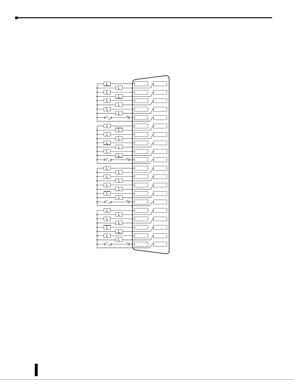
BX-xxND3 Sinking/Sourcing 12–24 VDC Input, continued
Discrete Input Wiring Diagrams, 32-point module
Source
+
+12-24V
Source
+
+12-24V
4
0
5
1
6
+
+
2
7
3
1C
1C
12
8
13
9
14
10
15
11
2C
2C
20
16
21
17
22
18
23
19
3C
3C
28
24
29
25
30
26
31
27
4C
4C
Source
+
+12-24V
Source
+
+
+
+12-24V
7-12
BRX User Manual, 4th Edition, Rev. F
BX-xxNB 12–24 VAC Input
U
C
US
Chapter 7: BRX Digital I/O Expansion Modules
L
R
INPUT
1C
0
1
X
2
3
2C
4
5
X
6
7
BX-08NB
BX-08NB
Input Module
8-pt, 12–24 VAC
INPUT
1C
0
1
X
2
3
2C
4
5
X
6
7
3C
8
9
X
10
11
BX-12NB
BX-12NB
Input Module
12-pt, 12–24 VAC
INPUT
1C
0
1
2
3
2C
4
5
6
7
X
3C
8
9
10
11
4C
12
13
14
15
BX-16NB
BX-16NB
Input Module
16-pt, 12–24 VAC
Terminal Blocks
or ZIPLink Cables
Sold Separately
We recommend using prewired ZIPLink cables and
connection modules.
If you wish to hand-wire your module, a removable
terminal block is available. See Wiring Termination
Selection in this chapter for all options.
IMPORTANT!
Hot-Swapping Information
Note: This device cannot be Hot Swapped.
BRX User Manual, 4th Edition, Rev. F
7-13
Chapter 7: BRX Digital I/O Expansion Modules
AC Input
X
12–24
All PLC units with 12-24 VDC_VAC inputs – E
BX-xxNB 12–24 VAC Input, continued
Discrete Input Specifications
BX-08NB BX-12NB BX-16NB
Input Type AC
Inputs per Module 8 12 16
Commons 2 (4pts / common) Isolated 3 (4pts / common) Isolated 4 (4pts / common) Isolated
Nominal Voltage Range 12–24 VAC
Input Voltage Range 9–30 VAC
Maximum Voltage 30VAC RMS
AC Frequency 47–63 Hz
Input Impedance 3kΩ @ 24VAC
Input Current (typical) 8mA @ 24VAC
Maximum Input Current 12mA @ 30VAC
Heat Dissipation 3.1 W Max 4.7 W Max 6.1 W Max
ON Voltage Level > 9.0 VAC
OFF Voltage Level < 2.0 VAC
Minimum ON Current 5.0 mA (9V required-guarantee ON state)
Maximum OFF Current 2.0 mA
OFF-ON Response 10ms
ON-OFF Response 10ms
Status Indicators Logic Side, Green
Software Version Required Do-more! Designer version 2.0 or later
Discrete Input Wiring Diagram
nC
0
1
2
3
VAC
Internal Circuitry
Logical Input
IN
COM
7-14
BRX User Manual, 4th Edition, Rev. F

BX-xxNA 120–240 VAC Input
C
US
INPUT
1C
0
1
X
2
3
2C
4
5
X
6
7
BX-08NA
BX-12NA
INPUT
Chapter 7: BRX Digital I/O Expansion Modules
U
L
R
INPUT
1C
1C
0
1
X
2
3
2C
4
5
X
6
7
3C
8
9
X
10
11
BX-16NA
0
1
2
3
2C
4
5
6
7
X
3C
8
9
10
11
4C
12
13
14
15
Terminal Blocks
or ZIPLink Cables
Sold Separately
BX-08NA
Input Module
8-pt, 120–240 VAC
We recommend using prewired ZIPLink cables
and connection modules.
If you wish to hand-wire your module, a
removable terminal block is available. See
Wiring Termination Selection in this chapter for
all options.
BX-12NA
Input Module
12-pt, 120–240 VAC
IMPORTANT!
BX-16NA
Input Module
16-pt, 120–240 VAC
Hot-Swapping Information
Note: This device cannot be Hot Swapped.
BRX User Manual, 4th Edition, Rev. F
7-15

Chapter 7: BRX Digital I/O Expansion Modules
AC Input
X
DI 110/220VAC Input
BX-xxNA 120–240 VAC Input, continued
Discrete Input Specifications
BX-08NA BX-12NA BX-16NA
Input Type AC
Inputs per Module 8 12 16
Commons 2 (4pts / common) Isolated 3 (4pts / common) Isolated 4 (4pts / common) Isolated
Nominal Voltage Range 120–240 VAC
Input Voltage Range 85–264 VAC
Maximum Voltage 264VAC RMS
AC Frequency 47–63 Hz
Input Impedance 15kΩ
Input Current (typical)
Maximum Input Current
Heat Dissipation 2.8 W Max 4.2 W Max 5.5 W Max
ON Voltage Level > 85VAC
OFF Voltage Level < 40VAC
Maximum OFF Current 2.5 mA
OFF-ON Response 10ms
ON-OFF Response 10ms
Status Indicators Logic Side, Green
Software Version Required Do-more! Designer version 2.0 or later
9mA @ 120VAC,
13mA @ 220VAC
14mA @ 120VAC,
20mA @ 220VAC
Discrete Input Wiring Diagram
nC
0
1
2
3
COM
120-240 VAC
Internal Circuitry
IN
Logical Input
7-16
BRX User Manual, 4th Edition, Rev. F

BX-08SIM Simulator Input
U
C
US
L
R
Chapter 7: BRX Digital I/O Expansion Modules
INPUT
OFF ON
BX-08SIM
Discrete Input Specifications
0
1
2
3
X
4
5
6
7
IMPORTANT!
Input Type Simulator
Inputs per Module 8
Heat Dissipation 0.2 W Max
Status Indicators Logic Side, Green
Software Version Required
Hot-Swapping Information
Note: This device cannot be Hot Swapped.
Do-more! Designer
version 2.3 or later
BRX User Manual, 4th Edition, Rev. F
7-17

Chapter 7: BRX Digital I/O Expansion Modules
C
US
BX-xxTD1 Sinking 12–24 VDC Output
U
L
R
OUTPUT
1C
0
1
Y
2
3
2C
4
5
Y
6
7
BX-08TD1
BX-08TD1
Output Module
8-pt, 12–24 VDC
Sinking
Terminal Blocks or
ZIPLink Cable
Sold Separately
OUTPUT
1C
0
1
Y
2
3
2C
4
5
Y
6
7
3C
8
9
Y
10
11
BX-12TD1
BX-12TD1
Output Module
12-pt, 12–24 VDC
Sinking
Terminal Blocks or
ZIPLink Cable
Sold Separately
OUTPUT
1C
0
1
2
3
2C
4
5
6
7
Y
3C
8
9
10
11
4C
12
13
14
15
BX-16TD1
BX-16TD1
Output Module
16-pt, 12–24 VDC
Sinking
Terminal Blocks or
ZIPLink Cable
Sold Separately
OUTPUT
A B
Y
0
4
1
5
2
6
3
7
1C
1V
8
12
9
13
10
14
11
15
2C
2V
16
20
17
21
18
22
19
23
3C
3V
24
28
25
29
26
30
27
31
4C
4V
BX-32TD1
BX-32TD1
Output Module
32-pt, 12–24 VDC
Sinking
ZIPLink Cable
Sold Separately
We recommend using prewired ZIPLink
cables and connection modules.
See Wiring Termination Selection in this
chapter for all options.
IMPORTANT!
Hot-Swapping Information
Note: This device cannot be Hot Swapped.
7-18
BRX User Manual, 4th Edition, Rev. F

Chapter 7: BRX Digital I/O Expansion Modules
Y
Sinking Output
BX-xxTD1 Sinking 12–24 VDC Output, continued
Discrete Output Specifications
BX-08TD1 BX-12TD1 BX-16TD1 BX-32TD1
Output Type Sinking
Outputs per Module 8 12 16 32
Commons (Isolated) 2 3 4 4
Points per Common 4 4 4 8
Maximum Current per Common 2A
Nominal Voltage Range 12–24 VDC
Operating Voltage Range 5–36 VDC
Maximum Voltage 36VDC
Minimum Output Current 0.1 mA @ 24VDC
Maximum Output (Load) Current 0.5 A per output, no derating over temperature range
Maximum Inrush Current 5A for 50ms
Maximum Leakage Current 10µA
Heat Dissipation 1.0 W Max 1.4 W Max 1.6 W Max 3.2 W Max
ON Voltage Drop 0.05 VDC
OFF-ON Response < 5ms
ON-OFF Response < 2ms
Maximum Switching Frequency 143Hz
Overcurrent Protection N/A
Fuse Type User-supplied external fuse
Status Indicators
Software Version Required Do-more! Designer version 2.0 or later
Logic Side, Green (32-point module has 16 LEDs for half
of outputs, selectable via A/B switch)
Do-more!
Designer
version 2.3
or later
Discrete Output Wiring Diagram for 8, 12 and 16-point modules
nC
LOAD
LOAD
LOAD
LOAD
BRX User Manual, 4th Edition, Rev. F
0
1
2
3
Logic
Output
OUTPUT
LOAD
COM
12-24 VDC
7-19
Chapter 7: BRX Digital I/O Expansion Modules
BX-xxTD1 Sinking 12–24 VDC Output, continued
Discrete Output Wiring Diagrams, 32-point module
12-24 VDC
12-24 VDC
12-24 VDC
1C
2C
3C
0
1
2
3
8
9
10
11
16
17
18
19
24
25
4
5
6
7
1V
12
13
14
15
2V
20
21
22
23
3V
28
29
12-24 VDC
4C
26
27
30
31
4V
7-20
BRX User Manual, 4th Edition, Rev. F
BX-xxTD2 Sourcing 12–24 VDC Output
U
C
US
Chapter 7: BRX Digital I/O Expansion Modules
L
R
OUTPUT
1C
0
1
Y
2
3
2C
4
5
Y
6
7
BX-08TD2
BX-08TD2
Output Module
8-pt, 12–24 VDC
Sourcing
Terminal Blocks or
ZIPLink Cable
Sold Separately
OUTPUT
1C
0
1
Y
2
3
2C
4
5
Y
6
7
3C
8
9
Y
10
11
BX-12TD2
BX-12TD2
Output Module
12-pt, 12–24 VDC
Sourcing
Terminal Blocks or
ZIPLink Cable
Sold Separately
OUTPUT
1C
0
1
2
3
2C
4
5
6
7
Y
3C
8
9
10
11
4C
12
13
14
15
BX-16TD2
BX-16TD2
Output Module
16-pt, 12–24 VDC
Sourcing
Terminal Blocks or
ZIPLink Cable
Sold Separately
OUTPUT
A B
Y
0
4
1
5
2
6
3
7
1C
1V
8
12
9
13
10
14
11
15
2C
2V
16
20
17
21
18
22
19
23
3C
3V
24
28
25
29
26
30
27
31
4C
BX-32TD2
4V
BX-32TD2
Output Module
32-pt, 12–24 VDC
Sourcing
ZIPLink Cable
Sold Separately
We recommend using prewired ZIPLink
cables and connection modules.
See Wiring Termination Selection in this
chapter for all options.
BRX User Manual, 4th Edition, Rev. F
IMPORTANT!
Hot-Swapping Information
Note: This device cannot be Hot Swapped.
7-21

Chapter 7: BRX Digital I/O Expansion Modules
Y
Sourcing Output
BX-xxTD2 Sourcing 12–24 VDC Output, continued
Discrete Output Specifications
BX-08TD2 BX-12TD2 BX-16TD2 BX-32TD2
Output Type Sourcing
Outputs per Module 8 12 16 32
Commons (Isolated) 2 3 4 4
Points per Common 4 4 4 8
Maximum Current per Common 2A
Nominal Voltage Range 12–24 VDC
Operating Voltage Range 5–36 VDC
Maximum Voltage 36VDC
Minimum Output Current 0.1 mA @ 24VDC
Maximum Output (Load) Current 0.5 A per output, no derating over temperature range
Maximum Inrush Current 5A for 50ms
Maximum Leakage Current 10µA
Heat Dissipation 1.0 W Max 1.4 W Max 1.6 W Max 3.2 W Max
ON Voltage Drop 0.05 VDC
OFF-ON Response < 5ms
ON-OFF Response < 2ms
Maximum Switching Frequency 143Hz
Overcurrent Protection N/A
Fuse Type User-supplied external fuse
Status Indicators
Software Version Required Do-more! Designer version 2.0 or later
Logic Side, Green (32-point module has 16 LEDs for
half of outputs, selectable via A/B switch)
Do-more!
Designer
version 2.3
or later
7-22
Discrete Output Wiring Diagram for 8, 12 and 16-point modules
nC
LOAD
LOAD
LOAD
LOAD
BRX User Manual, 4th Edition, Rev. F
0
1
2
3
Logic
Output
12-24 VDC
COM
OUTPUT
LOAD

Chapter 7: BRX Digital I/O Expansion Modules
BX-xxTD2 Sourcing 12–24 VDC Output, continued
Discrete Output Wiring Diagrams, 32-point module
12-24 VDC
12-24 VDC
12-24 VDC
1C
10
2C
16
17
18
19
3C
24
25
0
1
2
3
8
9
11
4
5
6
7
1V
12
13
14
15
2V
20
21
22
23
3V
28
29
12-24 VDC
26
27
4C
30
31
4V
BRX User Manual, 4th Edition, Rev. F
7-23

Chapter 7: BRX Digital I/O Expansion Modules
C
US
Y
Sourcing Output
BX-16TF2 Sourcing 3–5 VDC Output
Discrete Output Specifications
OUTPUT
BX-16TF2
U
L
R
1C
0
1
2
3
2C
4
5
6
Terminal Blocks
7
3C
8
9
10
11
4C
12
13
14
15
or ZIPLink Cables
Sold Separately
Y
Output Type Sourcing
Outputs per Module 16
Commons 4
Maximum Current per Common 96mA
Power Supply Internal +5VDC
Peak Voltage 5.5 VDC
Minimum Output Current 0 µA
Maximum Output Current
Maximum Leakage Current 10µA
Heat Dissipation 1.2 W Max
ON Voltage Drop 0.05 VDC
ON-OFF Response <2ms
OFF-ON Response <5ms
Fuses, Overcurrent Protection N/A
Backplane Power Consumption 0.9 W
Status Indicators Logic Side, Green
Software Version Required Do-more! Designer version 2.8 or later
NEW
24mA per output, no derating over
temperature range
We recommend using prewired ZIPLink cables
and connection modules.
If you wish to hand-wire your module, a
removable terminal block is available. See
Wiring Termination Selection in this chapter for
all options.
IMPORTANT!
Hot-Swapping Information
Note: This device cannot be Hot Swapped.
Discrete Output Wiring Diagram
LOAD
LOAD
LOAD
LOAD
nC
0
1
2
3
Internal 5VDC
power to outputs
7-24
BRX User Manual, 4th Edition, Rev. F

BX-xxTR Relay Output
C
US
Chapter 7: BRX Digital I/O Expansion Modules
U
L
R
OUTPUT
1C
0
1
Y
2
3
2C
4
5
Y
6
7
BX-08TR
BX-08TR
Output Module 8-pt,
Relay Form A (SPST)
We recommend using prewired ZIPLink cables
and connection modules.
If you wish to hand-wire your module, a
removable terminal block is available. See
Wiring Termination Selection in this chapter for
all options.
OUTPUT
1C
0
1
Y
2
3
2C
4
5
Y
6
7
3C
8
9
Y
10
11
BX-12TR
BX-12TR
Output Module 12-pt,
Relay Form A (SPST)
IMPORTANT!
OUTPUT
1C
0
1
2
3
4
5
6
7
8
9
10
11
12
13
14
15
Terminal Blocks
or ZIPLink Cables
Sold Separately
2C
Y
3C
4C
BX-16TR
BX-16TR
Output Module 16-pt,
Relay Form A (SPST)
Hot-Swapping Information
Note: This device cannot be Hot Swapped.
NOTE: When using relay expansion modules, adding 32 or more relay points requires you to perform a power
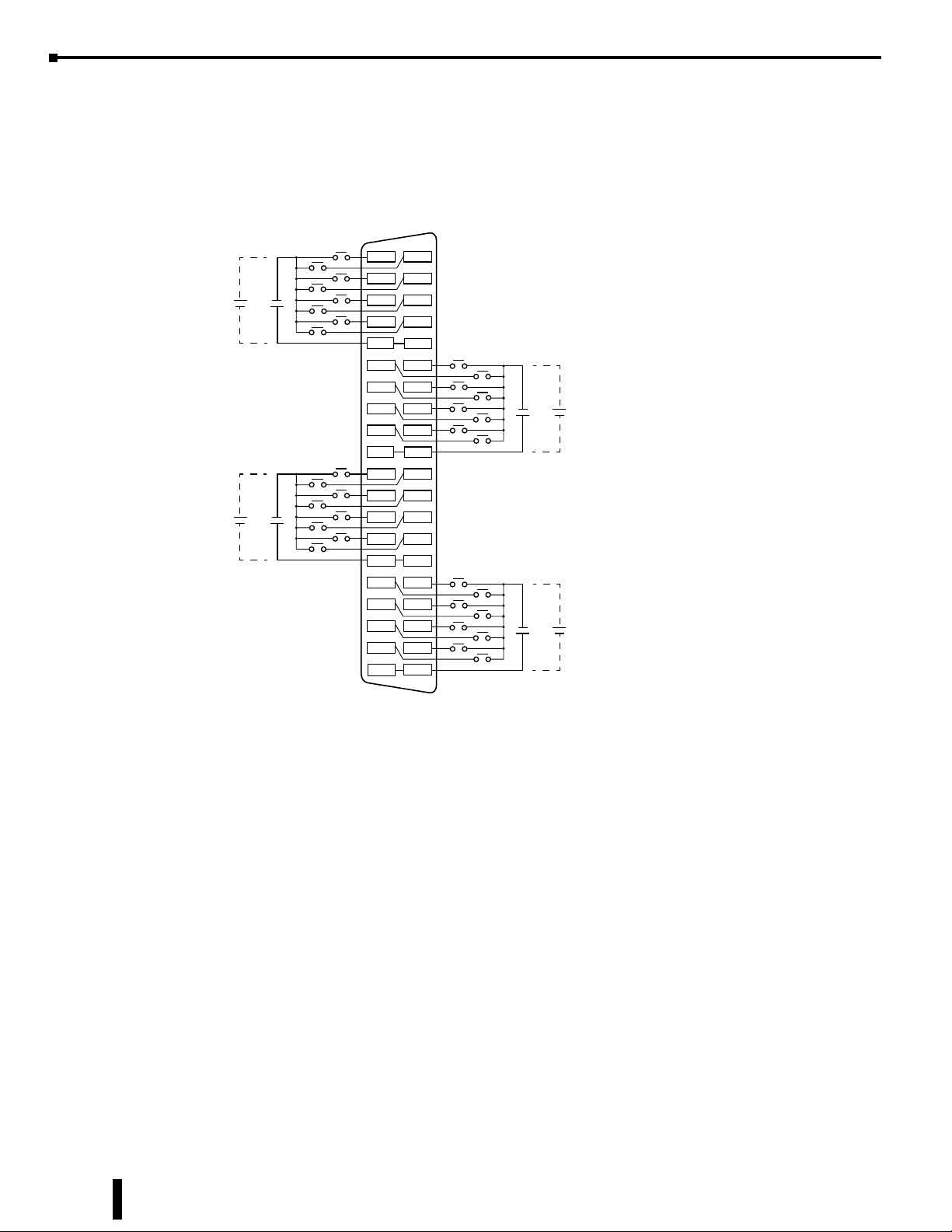
budget calculation. See Appendix C for more information.
BRX User Manual, 4th Edition, Rev. F
7-25
Chapter 7: BRX Digital I/O Expansion Modules
Y
Relay Output
PLC with Relay, form A – R and Expansion with Relay, form A, – TR
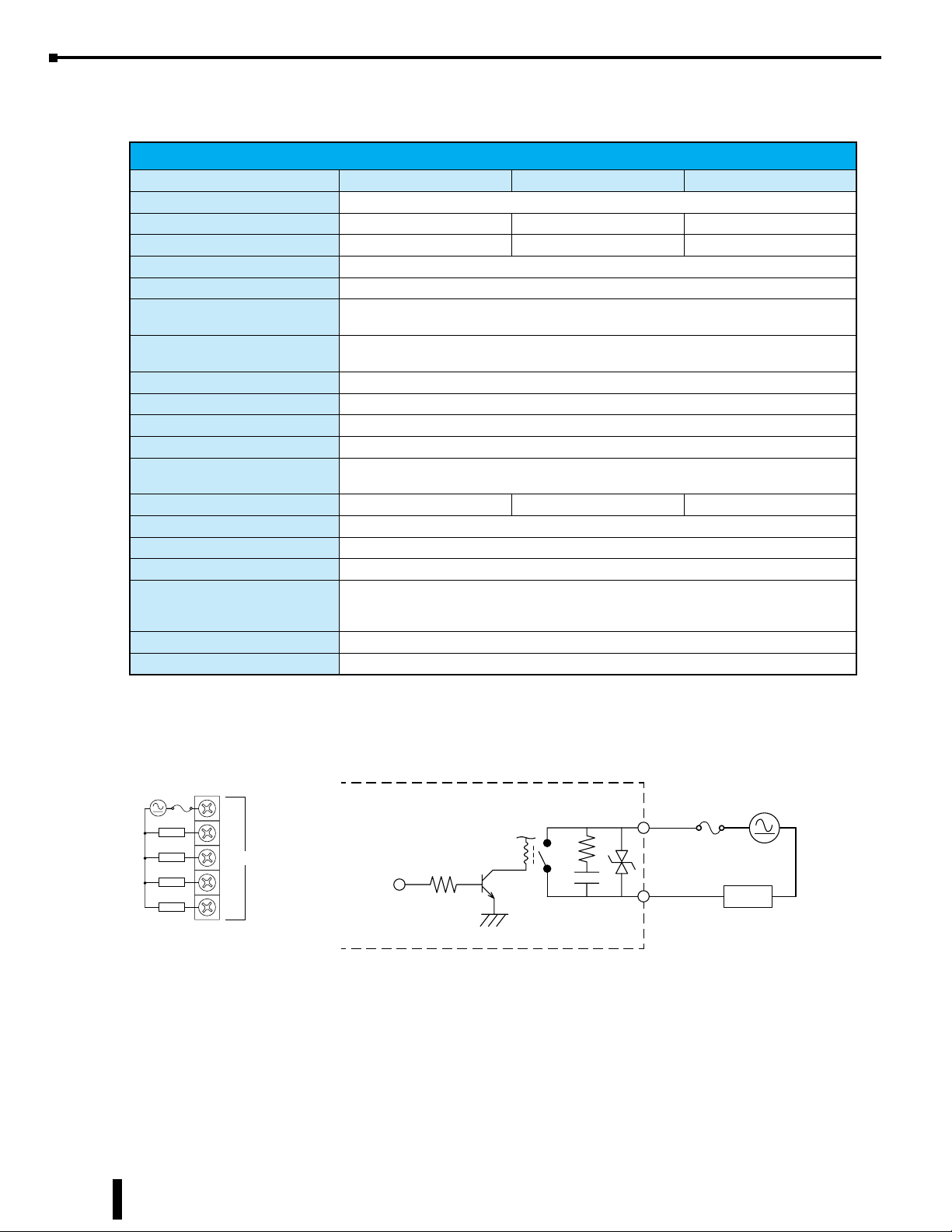
BX-xxTR Relay Output, continued
Discrete Output Specifications
BX-08TR BX-08TR BX-16TR
Output Type Relay, Form A (SPST)
Outputs per Module 8 12 16
Commons 2 (4pts / common) Isolated 3 (4pts / common) Isolated 4 (4pts / common) Isolated
Surge Suppression Yes
Maximum Current per Common 8A
Nominal Voltage Range
Operating Voltage Range
Maximum Voltage 60VDC, 264VAC
Minimum Output Current 0.1 mA @ 24V AC/DC
Maximum Output Current 2A
Maximum Inrush Current 5A for 50ms
Maximum Leakage Current
Heat Dissipation 4.9 W Max 7.3 W Max 9.8 W Max
ON Voltage Drop > 0.2 Vmax
Fuse Type User-supplied external fuse
Maximum Switching Frequency 10Hz
Relay Cycle Life
Mechanical Endurance
Electrical Endurance
Status Indicators Logic Side, Green
Software Version Required Do-more! Designer version 2.0 or later
12–48 VDC
24–240 VAC
5–60 VDC
5–264 VAC
1µA (DC),
300µA (AC) due to RC snubber circuit
5 Million Operations
120,000 Operations
Relay Output Wiring Diagram
nC
LOAD
LOAD
LOAD
LOAD
0
1
2
3
Internal Circuitry
Logic
Output
24-240 VAC
12-48 VDC
COM
OUTPUT
LOAD
7-26
BRX User Manual, 4th Edition, Rev. F

C
US
Y
Relay Output
NEW
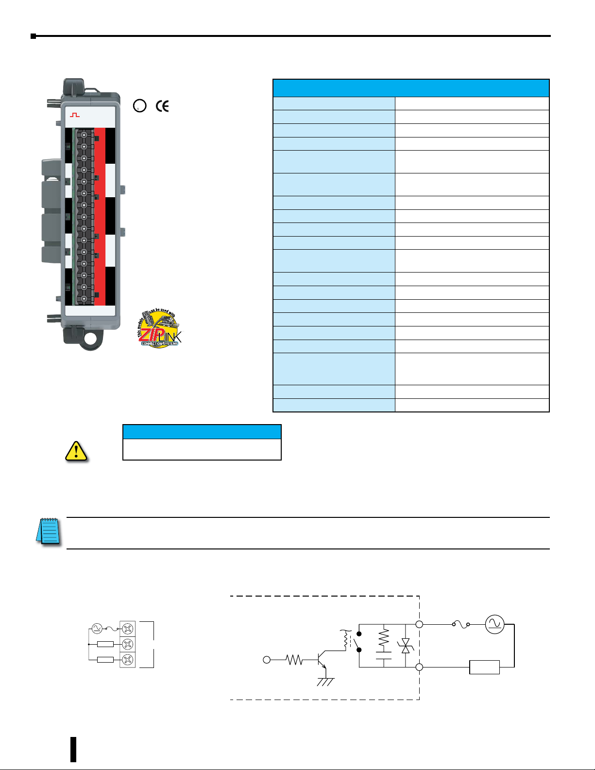
BX-xxTRZ Relay Output
Chapter 7: BRX Digital I/O Expansion Modules
OUTPUT
OUTPUT
1C
1C
0
0
1
1
Y
Y
2
2
3
3
2C
2C
4
4
5
5
Y
Y
6
6
7
7
BX-08TR
BX-08TRZ
BX-08TRZ
Output Module 8-pt,
Relay Form A (SPST)
No surge suppression
Terminal Blocks or
ZIPLink Cable
Sold Separately
U
L
R
BX-16TRZ
Output Module 16-pt,
Relay Form A (SPST)
No surge suppression
Terminal Blocks or
ZIPLink Cable
Sold Separately
OUTPUT
BX-16TRZ
Discrete Output Specifications
BX-08TRZ BX-16TRZ
1C
0
1
2
3
2C
4
5
6
7
Y
3C
8
9
10
11
4C
12
13
14
15
Output Type Relay, Form A (SPST)
Outputs per Module 8 16
Commons
2 (4pts / common)
Isolated
4 (4pts / common)
Isolated
Surge Suppression No
Maximum Current per Common 8A
Nominal Voltage Range 5–48 VDC, 24–240 VAC
Operating Voltage Range 5–60 VDC, 18–264 VAC
Maximum Voltage 60VDC, 264VAC
Minimum Output Current 0.1 mA @ 24VDC
Maximum Output Current 2A
Maximum Inrush Current 5A for 50ms
Maximum Leakage Current 1nA
Heat Dissipation 4.9 W Max 9.8 W Max
Backplane Power Consumption 1.7 W 3.4 W
ON Voltage Drop 0.2 Vmax
Relay Cycle Life
Mechanical Endurance
Electrical Endurance
5 Million Operations
120,000 Operations
Status Indicators Logic Side, Green
Software Version Required Do-more! Designer version 2.8 or later
IMPORTANT!
Hot-Swapping Information
We recommend using prewired ZIPLink
cables and connection modules.
If you wish to hand-wire your module,
a removable terminal block is available.
See Wiring Termination Selection in this
chapter for all options.
Relay Output Wiring Diagram
nC
LOAD
LOAD
LOAD
LOAD
0
1
2
3
Note: This device cannot be Hot Swapped.
BRX User Manual, 4th Edition, Rev. F
7-27
Chapter 7: BRX Digital I/O Expansion Modules
C
US
Y
Relay Output
C
PLC with Relay, form A – R and Expansion with Relay, form A, – TR
BX-05TRS Relay Output
U
L
OUTPUT
1C
NO
NC
2C
NO
NC
3C
Y
NO
NC
4C
NO
NC
5C
NO
NC
BX-05TRS
We recommend using prewired ZIPLink cables
and connection modules.
If you wish to hand-wire your module, a
removable terminal block is available. See
Wiring Termination Selection in this chapter for
all options.
R
Terminal Blocks
or ZIPLink Cables
Sold Separately
Discrete Output Specifications
Output Type Relay, Form C (SPDT)
Outputs per Module 5
Commons 5 Isolated
Maximum Current per Common 2A
Nominal Voltage Range
Operating Voltage Range
Maximum Voltage 60VDC, 264VAC
Minimum Output Current 0.1 mA @ 24V AC/DC
Maximum Output Current 2A
Maximum Inrush Current 5A for 50ms
Maximum Leakage Current
Heat Dissipation 3.8 W Max
ON Voltage Drop > 0.2 Vmax
ON-OFF Response <10ms
OFF-ON Response <10ms
Fuse Type User-supplied external fuse
Maximum Switching Frequency 10Hz
Relay Cycle Life
Mechanical Endurance
Electrical Endurance
Status Indicators Logic Side, Green
Software Version Required Do-more! Designer version 2.0 or later
12–48 VDC
24–240 VAC
5–60 VDC
5–264 VAC
1µA (DC),
300µA (AC) due to RC snubber circuit
10 Million Operations
50,000 Operations
IMPORTANT!
Hot-Swapping Information
Note: This device cannot be Hot Swapped.
NOTE: When using relay expansion modules, adding 32 or more relay points requires you to perform a power
budget calculation. See Appendix C for more information.
Relay Output Wiring Diagram
Internal Circuitry
nC
LOAD
LOAD
NO
NC
Logic
Output
24-240 VA
12-48 VDC
COM
OUTPUT
LOAD
7-28
BRX User Manual, 4th Edition, Rev. F
C
US
Y
Relay Output
NEW
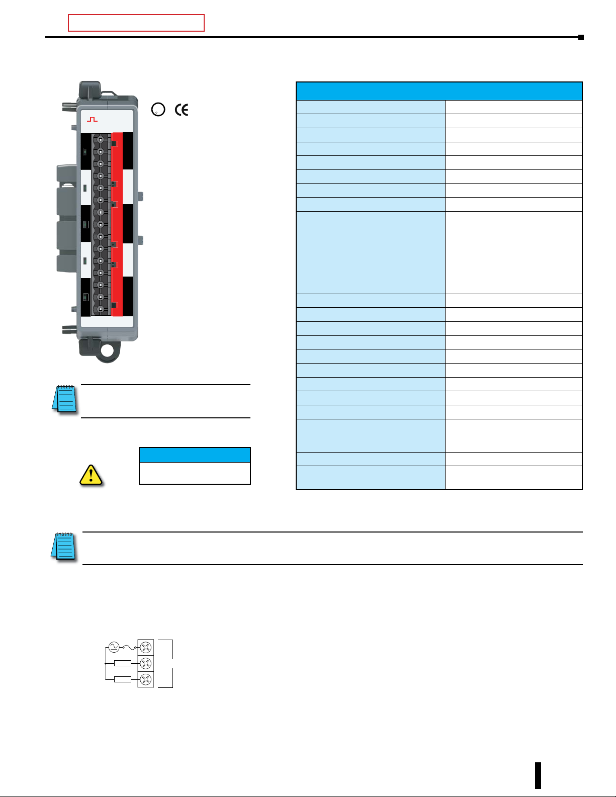
BX-05TRS-1 Relay Output
U
L
OUTPUT
OUTPUT
1C
1C
NO
NO
NC
NC
2C
2C
NO
NO
NC
NC
3C
3C
Y
NO
Y
NO
NC
NC
4C
4C
NO
NO
NC
NC
5C
5C
NO
NO
NC
NC
BX-05TRS
BX-05TRS-1
NOTE: This device does not support
ZIPLink Wiring Systems.
IMPORTANT!
R
Terminal Blocks
Sold Separately
Hot-Swapping Information
Note: This device cannot be
Hot Swapped.
Chapter 7: BRX Digital I/O Expansion Modules
Discrete Output Specifications
Output Type Relay, Form C (SPDT)
Outputs per Module 5
Commons 5 Isolated
Maximum Current per Common 8A
Nominal Voltage Range 5–48 VDC, 24–240 VAC
Operating Voltage Range 5–120 VDC, 18–264 VAC
Peak Voltage 120VDC, 264VAC
Minimum Output Current 0.1 mA @ 24VDC
Maximum Output Current
@30VDC Resistive Load
@50VDC Resistive Load
@120VDC Resistive Load
@120VAC Resistive Load
@240VAC Resistive Load
@120VAC Inductive 0.4 Power Factor
@240VAC Inductive 0.4 Power Factor
Maximum Inrush Current 15A for 50ms
Maximum Leakage Current 10µA
Heat Dissipation 308W Max
Backplane Power Consumption 1.8 W Max
ON Voltage Drop 0.2 Vmax
ON-OFF Response <10ms
OFF-ON Response <10ms
Fuse Type N/A
Maximum Switching Frequency 10Hz
Relay Cycle Life
Mechanical Endurance
Electrical Endurance
Status Indicators Logic Side, Green
Software Version Required
8A
3A
0.5 A
8A
5A
5A
2A
5 Million Operations
120,000 Operations
Do-more! Designer version 2.8
or later
NOTE: When using relay expansion modules, adding 32 or more relay points requires you to perform a power
budget calculation. See Appendix C for more information.
Relay Output Wiring Diagram
nC
LOAD
LOAD
BRX User Manual, 4th Edition, Rev. F
NO
NC
7-29
Chapter 7: BRX Digital I/O Expansion Modules
U
C
US
BX-xxTA 120–240 VAC Output
L
R
OUTPUT
1C
0
1
Y
2
3
2C
4
5
Y
6
7
BX-08TA
BX-08TA
Output Module
8-pt, 120–240 VAC
OUTPUT
1C
0
1
Y
2
3
2C
4
5
Y
6
7
3C
8
9
Y
10
11
BX-12TA
BX-12TA
Output Module
12-pt, 120–240 VAC
Terminal Blocks
or ZIPLink Cables
Sold Separately
We recommend using prewired ZIPLink cables and
connection modules.
If you wish to hand-wire your module, a removable
terminal block is available. See Wiring Termination
Selection in this chapter for all options.
IMPORTANT!
Hot-Swapping Information
Note: This device cannot be Hot Swapped.
7-30
BRX User Manual, 4th Edition, Rev. F
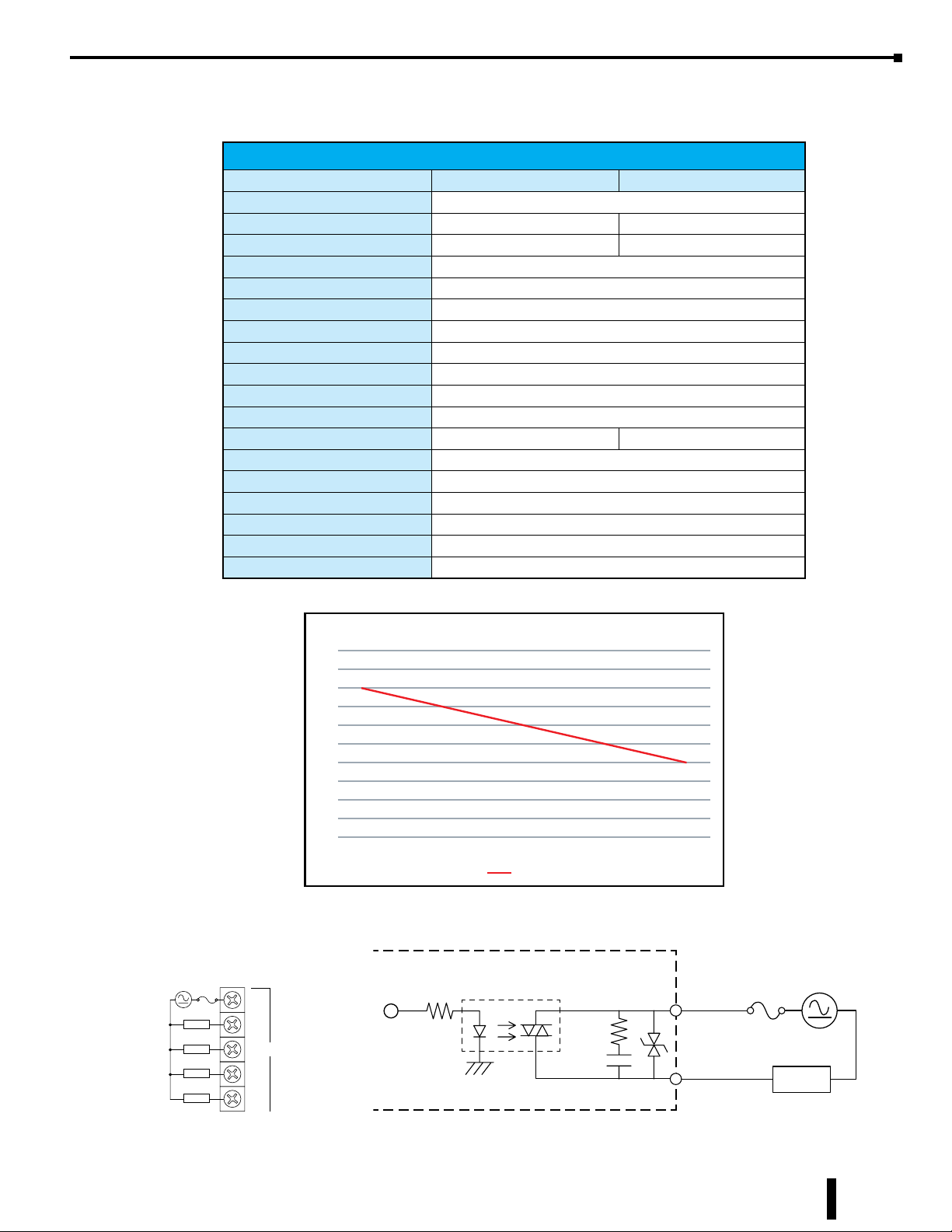
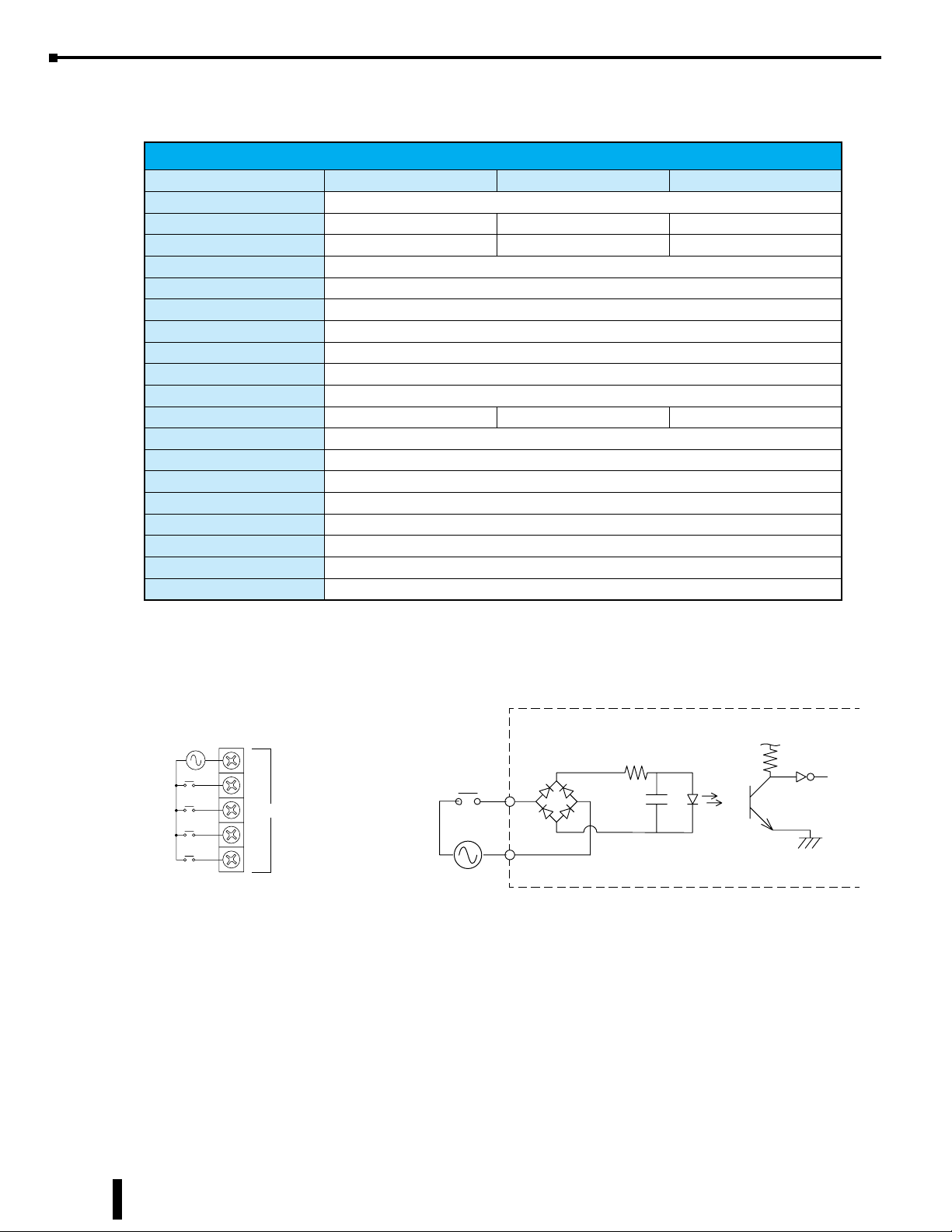
BX-xxTA 120–240 VAC Output, continued
Y
Triac Output
Expansion with 120_240 VAC Outputs – TA
Discrete Output Specifications
BX-08TA BX-12TA
Output Type Triac
Outputs per Module 8 12
Commons 2 (4 points/common) Isolated 3 (4 points/common) Isolated
Maximum Current per Common 2A
Nominal Voltage Range 120–240 VAC
Operating Voltage Range 5–258 VAC
Maximum Voltage 258VAC
Maximum Output Current 0.5 A across temp range
Current Derating Linear by Common: 2A @ 25°C - 1A @ 60°C
Maximum Inrush Current 5A for 50ms
Maximum Leakage Current 1µA
Heat Dissipation 4.8 W Max 7.1 W Max
ON Voltage Drop 2.5 Vmax
ON-OFF Response <10ms
OFF-ON Response <10ms
Fuse Type User-supplied external fuse
Status Indicators Logic Side, Green
Software Version Required Do-more! Designer version 2.0 or later
Chapter 7: BRX Digital I/O Expansion Modules
Triac Output Wiring Diagram
LOAD
LOAD
LOAD
LOAD
nC
BX-xxTA Derating Chart
2.50
2.25
2.00
1.75
1.50
1.25
1.00
0.75
0.50
0.25
0.00
25°C 30°C35°C40°C45°C50°C55°C60°C
Amps
Internal Circuitry
COM
0
1
2
3
Logic
Output
OUTPUT
120-240 VAC
LOAD
BRX User Manual, 4th Edition, Rev. F
7-31

Chapter 7: BRX Digital I/O Expansion Modules
U
C
BX-08CD3R Combination DC Input/Relay Output
The BX-08CD3R Combination DC Input/Relay Output Expansion Module provides a total of eight (8)
points; four (4) 12–24 VDC sink/source inputs and four (4) Form A (SPST) relay outputs.
Module Specifications
L
R
US
Heat Dissipation 4.1 W Max
Status Indicators Logic Side, Green
Software Version Required Do-more! Designer version 2.0 or later
BX-08CD3R
We recommend using prewired ZIPLink cables
and connection modules.
If you wish to hand-wire your module, a
removable terminal block is available. See
Wiring Termination Selection in this chapter for
all options.
IMPORTANT!
Note: This device cannot be Hot Swapped.
1C
0
1
X
2
3
1C
0
1
Y
2
3
Hot-Swapping Information
Terminal Blocks
or ZIPLink Cables
Sold Separately
Discrete Input Specifications
Input Type Sink/Source
Inputs per Module 4
Nominal Voltage Range 12–24 VDC
Input Voltage Range 9–30 VDC
Maximum Voltage 30VDC
Commons 1 (4 points/common)
Input Current (typical) 8mA @ 24VDC
Maximum Input Current 12mA @ 30VDC
Input Impedance 3kΩ @ 24VDC
ON Voltage Level > 9.0 VDC
OFF Voltage Level < 2.0 VDC
Minimum ON Current
Maximum OFF Current 2.0 mA
OFF-ON Response 2ms
ON-OFF Response 2ms
5.0 mA
(9V required-guarantee ON state)
Discrete Output Specifications
Output Type Relay, Form A (SPST)
Outputs per Module 4
Commons 1 (4 points/common)
Maximum Current per Common 8A
Nominal Voltage Range
Operating Voltage Range
Maximum Voltage 60VDC, 264VAC
Minimum Output Current 0.1 mA @24VDC
Maximum Output Current 2A
Maximum Inrush Current 5A for 50ms
Maximum Leakage Current 1µA
ON Voltage Drop 0.2 Vmax
ON-OFF Response <10ms
OFF-ON Response <10ms
Fuse Type User-supplied external fuse
Maximum Switching Frequency 10Hz
Relay Cycle Life
Mechanical Endurance
Electrical Endurance
12–48 VDC
24–240 VAC
5–60 VDC
5–264 VAC
5 Million Operations
120,000 Operations
7-32
BRX User Manual, 4th Edition, Rev. F

Chapter 7: BRX Digital I/O Expansion Modules
Sinking Input
X
X
Sourcing Input
All Expansion units with 12-24 VDC inputs – ND3
Y
Relay Output
PLC with Relay, form A – R and Expansion with Relay, form A, – TR
BX-08CD3R Combination DC Input/Relay Output, continued
Discrete Input Wiring Diagrams
nC
0
1
2
3
nC
0
1
2
3
Sinking
Sourcing
12-24 VDC
IN
COM
Relay Output Wiring Diagrams
nC
LOAD
LOAD
LOAD
LOAD
0
1
2
3
Logic
Output
Internal Circuitry
Internal Circuitry
Logical Input
24-240 VAC
12-48 VDC
COM
OUTPUT
LOAD
BRX User Manual, 4th Edition, Rev. F
7-33

Chapter 7: BRX Digital I/O Expansion Modules
U
C
US
BX-xxCD3D1 Combination DC Input/Sinking DC Output
The BX-xxCD3D1 Combination DC Input/Sourcing Output Expansion Modules provides a total of twelve
(12) or sixteen (16) points; eight (8) 12–24 VDC sink/source inputs and either four (4) or eight (8) 12-24
VDC sinking outputs.
L
R
Terminal Blocks
or ZIPLink Cables
Sold Separately
IN/OUT
X
X
Y
BX-12CD3D1
IN/OUT
1C
1C
0
1
2
3
2C
4
5
6
7
1C
0
1
2
3
BX-16CD3D1
0
1
2
3
X
2C
4
5
6
7
1C
0
1
2
3
Y
2C
4
5
6
7
BX-12CD3D1
Combination Discrete Module
Input: 8-pt, 12–24 VDC, Sink/Source,
Output: 4-pt, 12–24 VDC, Sinking
We recommend using prewired ZIPLink cables
and connection modules.
If you wish to hand-wire your module, a
removable terminal block is available. See
Wiring Termination Selection in this chapter
for all options.
BX-16CD3D1
Combination Discrete Module
Input: 8-pt, 12–24 VDC, Sink/Source,
Output: 8-pt, 12–24 VDC, Sinking
IMPORTANT!
Note: This device cannot be Hot Swapped.
Hot-Swapping Information
7-34
BRX User Manual, 4th Edition, Rev. F

Chapter 7: BRX Digital I/O Expansion Modules
BX-xxCD3D1 Combination DC Input/Sinking DC Output, continued
Module Specifications
BX-12CD3D1 BX-16CD3D1
Heat Dissipation 3.5 W Max 3.9 W Max
Status Indicators Logic Side, Green
Software Version Required Do-more! Designer version 2.0 or later
Discrete Input Specifications
BX-12CD3D1 BX-16CD3D1
Input Type Sink/Source
Inputs per Module 8
Commons 2 (4 points/common) Isolated
Nominal Voltage Range 12–24 VDC
Input Voltage Range 9–30 VDC
Maximum Voltage 30VDC
Input Impedance 3kΩ @ 24VDC
Input Current (typical) 8mA @ 24VDC
Maximum Input Current 12mA @ 30VDC
ON Voltage Level > 9.0 VDC
OFF Voltage Level < 2.0 VDC
Minimum ON Current 5.0 mA (9V required-guarantee ON state)
Maximum OFF Current 2.0 mA
OFF-ON Response 2ms
ON-OFF Response 2ms
Discrete Output Specifications
Output Type Sinking
Outputs per Module 4 8
Commons 1 (4 points/common) 2 (4 points/common) Isolated
Maximum Current per Common 2A
Nominal Voltage Range 12–24 VDC
Operating Voltage Range 5–36 VDC
Maximum Voltage 36VDC
Minimum Output Current 0.1 mA @ 24VDC
Maximum Output Current 0.5 A per output, no derating over temperature range
Maximum Inrush Current 5A for 50ms
Maximum Leakage Current 10µA
ON Voltage Drop 0.05 VDC
Fuse Type User-supplied external fuse
OFF-ON Response < 5ms
ON-OFF Response < 2ms
BRX User Manual, 4th Edition, Rev. F
BX-12CD3D1 BX-16CD3D1
7-35

Chapter 7: BRX Digital I/O Expansion Modules
Sinking Input
X
X
Sourcing Input
12-24 VDC
All Expansion units with 12-24 VDC inputs – ND3
Y
Sinking Output
BX-xxCD3D1 Combination DC Input/DC Sinking Output, continued
Discrete Input Wiring Diagrams
nC
0
1
2
3
nC
0
1
2
3
Sinking
Sourcing
IN
COM
Discrete Output Wiring Diagrams
nC
LOAD
LOAD
LOAD
LOAD
0
1
2
3
Logic
Output
Internal Circuitry
Logical Input
OUTPUT
LOAD
COM
12-24 VDC
7-36
BRX User Manual, 4th Edition, Rev. F

Chapter 7: BRX Digital I/O Expansion Modules
U
C
US
BX-xxCD3D2 Combination DC Input/Sourcing DC Output
The BX-xxCD3D2 Combination Input/Output Expansion Modules provides a total of twelve (12) or sixteen
(16) points; eight (8) 12–24 VDC sink/source inputs and either four (4) or eight (8) 12-24 VDC sourcing
outputs.
IN/OUT
X
X
Y
BX-12CD3D2
1C
0
1
2
3
2C
4
5
6
7
1C
0
1
2
3
IN/OUT
X
Y
BX-16CD3D2
1C
0
1
2
3
2C
4
5
6
7
1C
0
1
2
3
2C
4
5
6
7
L
R
Terminal Blocks
or ZIPLink Cables
Sold Separately
BX-12CD3D2
Combination Discrete Module
Input: 8-pt, 12–24 VDC, Sink/Source
Output: 4-pt, 12–24 VDC, Sourcing
We recommend using prewired ZIPLink cables
and connection modules.
If you wish to hand-wire your module, a
removable terminal block is available. See Wiring
Termination Selection in this chapter for all
options.
IMPORTANT!
BX-16CD3D2
Combination Discrete Module
Input: 8-pt, 12–24 VDC, Sink/Source,
Output: 8-pt, 12–24 VDC, Sourcing
Hot-Swapping Information
Note: This device cannot be Hot Swapped.
BRX User Manual, 4th Edition, Rev. F
7-37

Chapter 7: BRX Digital I/O Expansion Modules
BX-xxCD3D2 Combination
DC Input/Sourcing DC Output, continued
Module Specifications
BX-12CD3D2 BX-16CD3D2
Heat Dissipation 3.5 W Max 3.9 W Max
Status Indicators Logic Side, Green
Software Version Required Do-more! Designer version 2.0 or later
Discrete Input Specifications
BX-12CD3D2 BX-16CD3D2
Input Type Sink/Source
Inputs per Module 8
Commons 2 (4 points/common) Isolated
Nominal Voltage Range 12–24 VDC
Input Voltage Range 9–30 VDC
Maximum Voltage 30VDC
Input Impedance 3kΩ @ 24VDC
Input Current (typical) 8mA @ 24VDC
Maximum Input Current 12mA @ 30VDC
ON Voltage Level > 9.0 VDC
OFF Voltage Level < 2.0 VDC
Minimum ON Current 5.0 mA (9V required-guarantee ON state)
Maximum OFF Current 2.0 mA
OFF-ON Response 2ms
ON-OFF Response 2ms
7-38
Discrete Output Specifications
BX-12CD3D2 BX-16CD3D2
Output Type Sourcing
Outputs per Module 4 8
Commons 1 (4 points/common) 2 (4 points/common) Isolated
Maximum Current per Common 2A
Nominal Voltage Range 12–24 VDC
Operating Voltage Range 5–36 VDC
Maximum Voltage 36VDC
Minimum Output Current 0.1 mA @ 24VDC
Maximum Output Current 0.5 A per output, no derating over temperature range
Maximum Inrush Current 5A for 50ms
Maximum Leakage Current 10µA
ON Voltage Drop 0.05 VDC
Fuse Type User-supplied external fuse
OFF-ON Response < 5ms
ON-OFF Response < 2ms
BRX User Manual, 4th Edition, Rev. F

Chapter 7: BRX Digital I/O Expansion Modules
Sinking Input
X
X
Sourcing Input
12-24 VDC
All Expansion units with 12-24 VDC inputs – ND3
Y
Sourcing Output
BX-xxCD3D2 Combination DC Input/DC Sourcing Output, continued
Discrete Input Wiring Diagrams
nC
0
1
2
3
nC
0
1
2
3
Sinking
Sourcing
Discrete Output Wiring Diagrams
Internal Circuitry
Logical Input
IN
COM
nC
LOAD
LOAD
LOAD
LOAD
0
1
2
3
Logic
Output
12-24 VDC
COM
OUTPUT
LOAD
BRX User Manual, 4th Edition, Rev. F
7-39

Chapter 7: BRX Digital I/O Expansion Modules
U
C
BX-16CF3F2 Combination DC Input/DC Sourcing Output
The BX-16CF3F2 Combination DC Input/DC Sourcing Output Expansion Module provides a total of
sixteen (16) points; eight (8) 3–5 VDC sink/source inputs and eight (8) 3–5 VDC sourcing outputs.
Module Specifications
L
R
IN/OUT
BX-16CF3F2
We recommend using prewired ZIPLink cables
and connection modules.
If you wish to hand-wire your module, a
removable terminal block is available. See
Wiring Termination Selection in this chapter for
all options.
IMPORTANT!
Note: This device cannot be Hot Swapped.
US
1C
0
1
2
3
X
2C
4
5
6
7
1C
0
1
2
3
Y
2C
4
5
6
7
Hot-Swapping Information
Terminal Blocks
or ZIPLink Cables
Sold Separately
Heat Dissipation 1.5 W Max
Backplane Power Consumption 1.0 W Max
Status Indicators Logic Side, Green
Software Version Required
Do-more! Designer version 2.8 or
later
Discrete Input Specifications
Input Type Sink/Source
Inputs per Module 8
Nominal Voltage Range 3–5 VDC
Input Voltage Range 2–6 VDC
Maximum Voltage 6VDC
Commons 2 (4 points/common)
Input Impedance 870Ω @ 5VDC
Input Current (typical) 6mA @ 5VDC
Maximum Input Current 8mA @ 6VDC
ON Voltage Level > 2.0 VDC
OFF Voltage Level < 0.8 VDC
Minimum ON Current
Maximum OFF Current 0.5 mA
OFF-ON Response 2ms
ON-OFF Response 2ms
1.2 mA (2.0 V required to guarantee
ON state)
Discrete Output Specifications
Output Type Sourcing
Outputs per Module 8
Commons 2 (4 points/common)
Maximum Current per Common 96mA
Power Supply Internal +5VDC
Peak Voltage 5.5 VDC
Minimum Output Current 0µA
Maximum Output Current
Maximum Leakage Current 10µA
ON Voltage Drop 0.05 VDC
Fuse Type N/A
OFF-ON Response < 5ms
ON-OFF Response < 2ms
24mA per output, no derating over
temperature range
NEW
7-40
BRX User Manual, 4th Edition, Rev. F

Sinking Input
X
X
Sourcing Input
Y
Sourcing Output
NEW
Chapter 7: BRX Digital I/O Expansion Modules
BX-16CF3F2 Combination DC Input/DC Sourcing Output, continued
Discrete Input Wiring Diagrams
nC
0
1
2
3
Discrete Output Wiring Diagrams
nC
Internal 5VDC
LOAD
LOAD
LOAD
0
1
2
power to outputs
nC
0
1
2
3
LOAD
3
BRX User Manual, 4th Edition, Rev. F
7-41
 Loading...