

Page 1
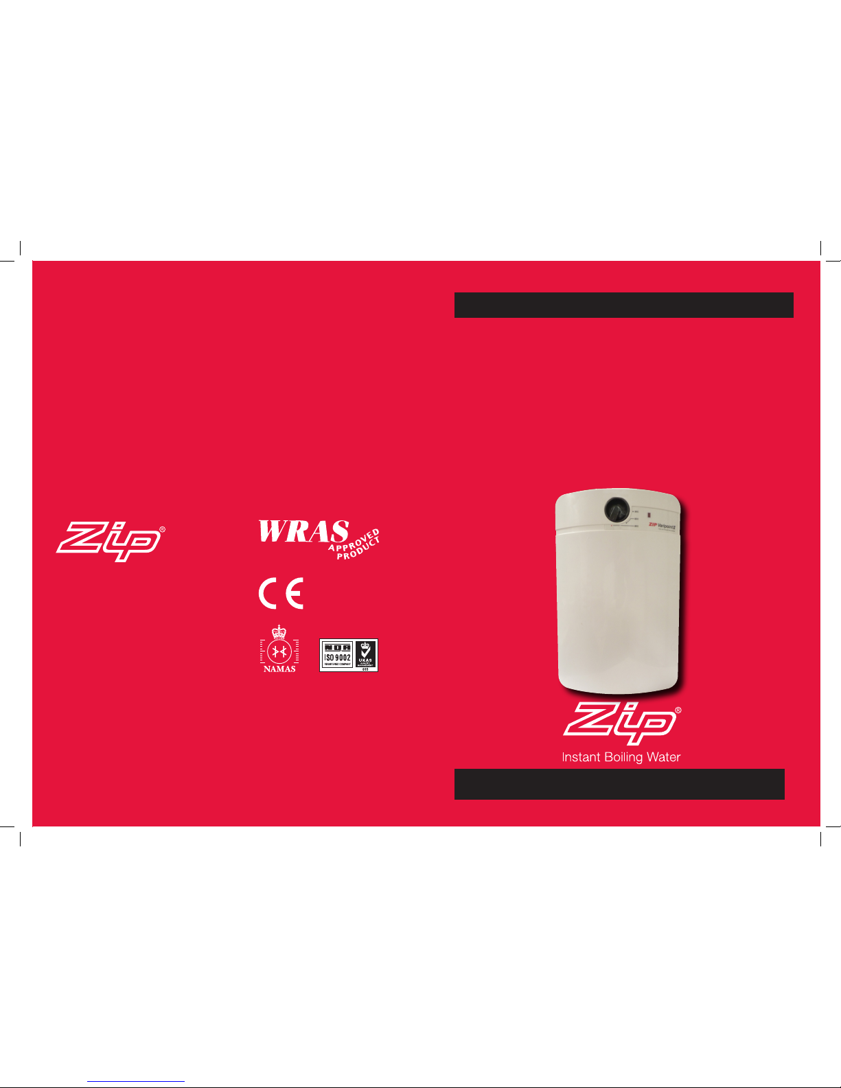
ZIP Varipoint II
Direct unvented water heaters
Models: VP103, VP153, VP103UB,
VP153UB
Installation, Maintenance and User Instructions
Please read these instructions carefully before commencing installation of this unvented
water heater. Please leave these instructions with the end user after installation.
Zip Heaters (UK) Ltd
14 Bertie Ward Way
Dereham
Norfolk
NR19 1TE
Telephone: 0845 6 005 005
Fax: 01362 692448
Web: www.zipheaters.co.uk
The terms ‘Zip’ and ‘Varipoint’
are registered trademarks
Issued October 2013 V1.01
Page 2

inside front cover
inside back cover
Page 3
Instructions. V1.01 Page 1 October / 2013
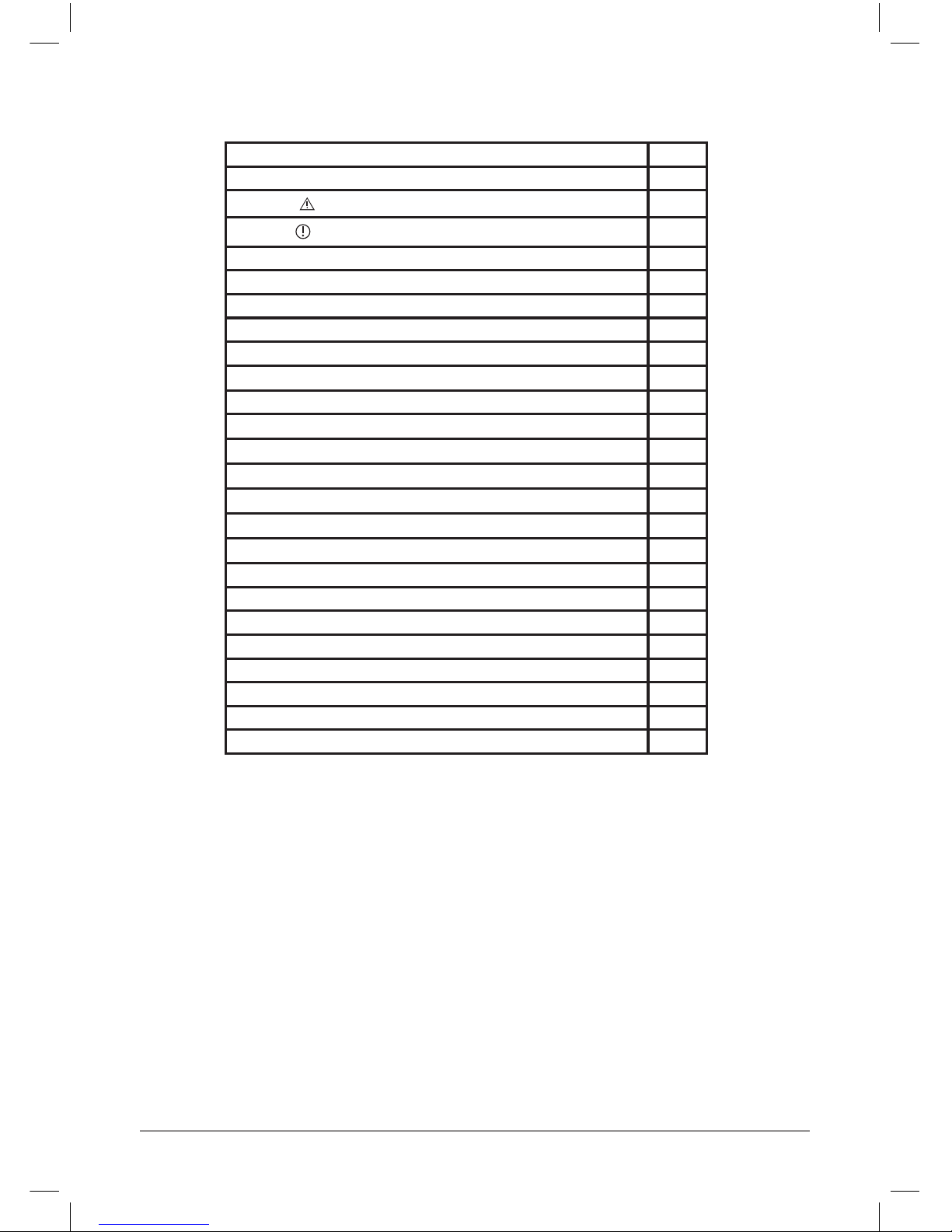
Approvals 1
Description 2
WARNINGS
3
CAUTIONS
4
Packed Contents 4
Accessories 4
Dimensions 4
Technical Data 5
Spare Parts 6
Installation 7
Requirements 7
Positioning 8
Wall Mounting 8
Plumbing and safety control arrangement 9
Installation Diagrams 10
Electrical installation & wiring 11
Wiring Diagram 11
Safety Cut-Out 11
Commissioning & Operation 12
Maintenance 13
Precautions 13
Schedule 14
De-installation 14
Fault nding 15
Warranty 16
Approvals
The Varipoint II models are approved to the LVD and EMC directives and CE endorsed.The
Varipoint II models have been examined, tested and found when correctly tted to comply
with the requirements of the United Kingdom Water Regulations / Byelaws (Scotland). The
products are listed under the WRAS (Water Regulations Advisory Scheme) Water Fittings and
Materials Directory.
Contents
Please read these instructions carefully before commencing installation of this unvented
Water Heater.
Installation must only be undertaken by a competent person, familiar with unvented electric
water heaters.
The Zip Varipoint II must be installed in accordance with these instructions and all current
legislation, codes of practice and regulations governing the installation of unvented hot water
cylinders in force at the time of installation
.
Please leave these instructions with the end user after installation. To ensure you have a copy of
the latest instructions visit www.zipheaters.co.uk
Page 4

Instructions. V1.01 Page 2 October / 2013
Description
If the hot water system is not used for two weeks or more, it is recommended
that a hot tap be turned on for several minutes at a sink, basin or bath, it is not
recommended that either a dishwasher, clothes washer or other appliance be used
before the heater is returned to service.
Capacity: Underbasin Overbasin
10 Litre VP103/UB VP103
15 Litre VP153/UB VP153
These instructions refer to the following models:
These instructions should guide you through the installation, maintenance and use of the
Zip Varipoint II, however, if you require any further information please call Zip customer
service on 0845 6 005 005.
• The Zip Varipoint II is an unvented water heater designed for connection directly to
incoming mains water supply and can serve one or more outlets using conventional
taps.
• Care should be taken that the unit being chosen can meet the demands of the outlets
being supplied.
• The casing is constructed of impact resistant plastic and heat losses are minimised by
the high efciency CFC free polyurethane foam insulation.
• The inner vessel is constructed from heavy guage copper tested to 1.6MPa (16 bar),
maximum working pressure 0.6MPa (6 bar).
• A manually resettable safety cut-out automatically cuts off the electrical supply to the
heating element in the event of a malfunction..
Page 5
Instructions. V1.01 Page 3 October / 2013
Safety Information
WARNINGS
• Installation, commissioning and maintenance of this appliance must only be
carried out by a competent installer who will then be responsible for adhering to all
relevant standards and regulations.
• The appliance must be disconnected from mains power supply before carrying out
any work involving live circuits.
• The appliance must be permanently connected to the supply through an isolating switch
with a contact separation of at least 3mm in all poles and be protected by a suitably rated
RCD.
• To protect the appliance, an MCB (miniature circuit breaker) or cartridge fuse must be
tted with a rating suitable for the nomi nal current of the appliance.
• The cross sectional area of the connection cable must be appropriate for the power rating
and location of the appliance. See Technical Data.
• The connecting cable must be adequately secured.
• This appliance must be earthed at all times.
• Check that the power supply is switched off prior to electrical connection.
• The appliance, its wiring and piping must not be modied in any way.
• In case of malfunction isolate the power supply immediately. In case of leaks also isolate
the water supply. Repairs must only be carried out by Zip Heaters (UK) Ltd or an authorised
Zip service engineer.
• Temperatures in excess of approximately 43°C are perceived as hot, especially by
children, and may cause a feeling of burning.
• This appliance must not be used by any person (inclu ding children) with limited physical,
sensorial or mental abilities or failing experience and/or knowledge unless they are
supervised by a person responsible for their safety or have received instructions about
how to use the appliance.
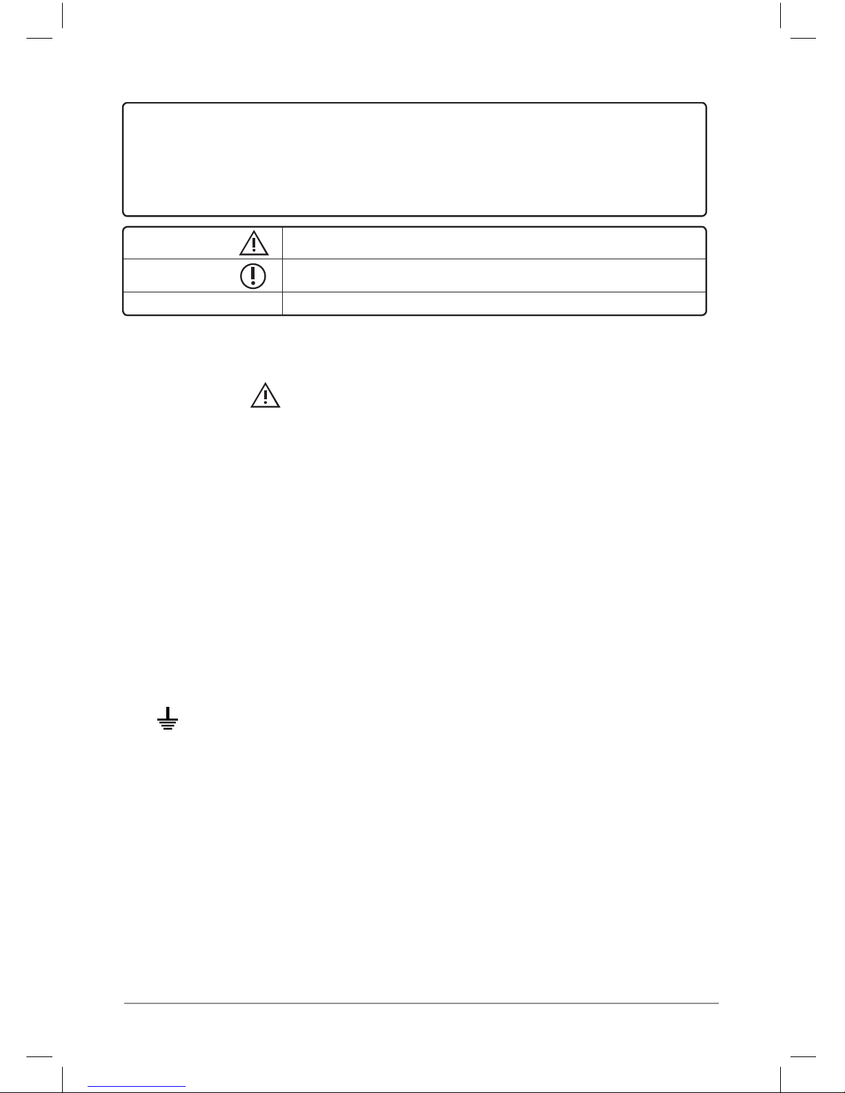
WARNING: Situations that could cause injury to yourself or others.
CAUTION: Situations that could cause damage to your appliance or other equipment.
NOTE: Notes, usage tips or additional information.
IMPORTANT:
PLEASE READ THESE INSTRUCTIONS CAREFULLY.
NOTE THE SAFE OPERATIONAL REQUIREMENTS, WARNINGS AND CAUTIONS. USE THIS PRODUCT
CORRECTLY AND WITH CARE FOR THE PURPOSE FOR WHICH IT IS INTENDED. FAILURE TO DO
SO MAY CAUSE DAMAGE AND/OR PERSONAL INJURY, AND WILL INVALIDATE THE WARRANTY.
RETAIN THESE INSTRUCTIONS FOR FUTURE USE.
Possible New Statement
Page 6
Instructions. V1.01 Page 4 October / 2013
CAUTIONS
• Children should be supervised in order to make sure that they do not play with the appliance.
• The appliance must not be subjected to pressure exceeding 0.6 MPa (6 bar). For supply
pressures exceeding 0.35MPa (3.5 bar) it is recommended that a pressure reducing
valve be installed. _
• The appliance must only be used when correctly installed and in perfect working order.
• The appliance must be installed in a frost-free room and must never be exposed to frost.
• The appliance must be completely lled with water before being switched on.
• The Varipoint II is intended for connection to mains supply only. In any other case please
contact Zip on 0845 6 005 005 for advice.
• Zip Heaters (UK) Ltd cannot be held liable for any damages caused by failure to
observe these instructions.
• It is recommended that an HE45004 Water Block is tted in the water supply line to
minimise the potential damage in the event of any leakage.
Packed Contents
Please check that the items below have been supplied in the Heater Unit package.
Wall Bracket x1
Expansion Relief Valve(1/2”BSP) x1
Temperature and Pressure Valve x1
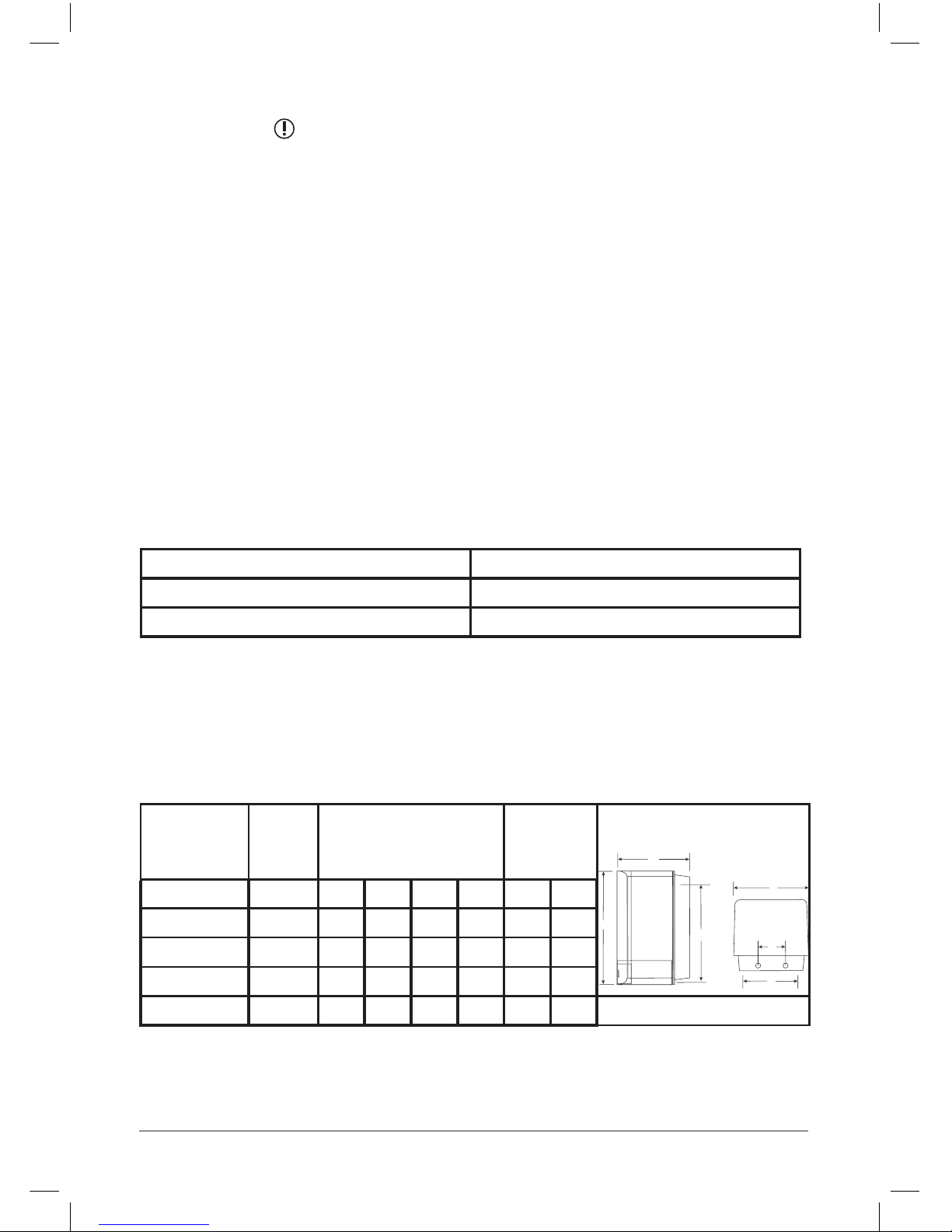
Dimensions
Model Capacity
(litres)
Dimensions
(mm)
Fixing
Centres
(mm)
A B C D E F
VP103 10 452 300 285 60 420 142
VP103/UB 10 452 300 285 60 335 142
VP153 15 452 300 285 60 420 142
VP153/UB 15 452 300 285 60 335 142
Accessories :
AQ2: Expansion vessel and Check valve.
AQ3: Combined pressure reducer and line strainer.
AQ4: Thermostatic blending valve complete with 2 check valves.
HE45004: Water block.
A
C
E
B
D
F
Page 7
Instructions. V1.01 Page 5 October / 2013
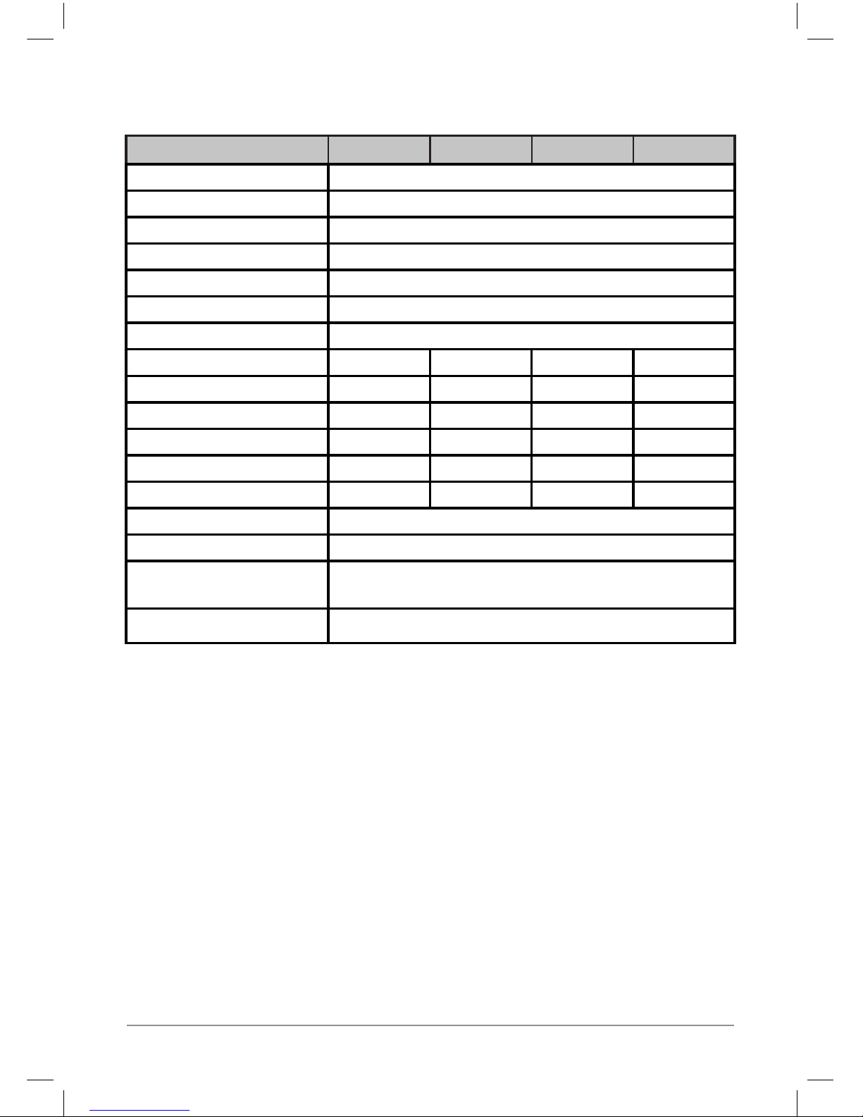
Technical data
Model VP103 VP153 VP103/UB VP153/UB
Nominal supply voltage 1/N/PE 230V~
Power rating (kW) 2.2
Rated Current (A) 9.6
Element type Embedded Rod
Water vessel Heavy Gauge Copper tested to 1.6 MPa (16 bar)..
Maximum working pressure 0.6 MPa (6 bar).
Temp. Adjustment range 6°C~75°C ± 3°C
Capacity 10 Litre 15 Litre 10 Litre 15 Litre
Weight (kg) Full 16.5 22.5 16.5 22.5
Weight (kg) Empty 6.5 7.5 6.5 7.5
Heat up time (15°C to 65°C) 16 mins 24 mins 16 mins 24 mins
Re-heat time (70% vol.) 11 mins. 17 mins. 11 mins. 17 mins.
Heat Loss(kWh/24 hrs) 0.36 0.50 0.41 0.58
Connection tting 1/2” BSP
Thermal cut out Manually resettable set to 84 ± 3ºC.
Safety features
Expansion relief valve set to 6 bar. (supplied)
T&P valve set to 90ºC/7 bar. (supplied)
Protection class IP24
All data quoted at nominal supply voltage.
Page 8
Instructions. V1.01 Page 6 October / 2013
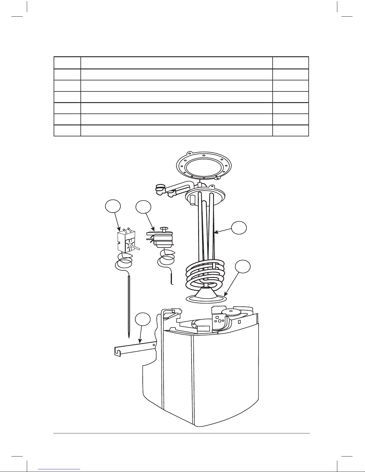
Spare parts
1
4
5
2
3
Item Description Part No
1 Element 2.2 kW for overbasin models VP0301
1 Element 2.2 kW for underbasin models VP0302
2 Thermostat VP0303
3 Ressettable cut-out VP0304
4 Element Gasket VP0317
5 Wall xing bracket VP0322
Page 9

Instructions. V1.01 Page 7 October / 2013
Installation
1. Before starting installation the WARNINGS (page 3) and CAUTIONS (page
4) should be read and fully understood. If in doubt , or in need of further guidance,
please call Zip Customer Service on 0845 6 005 005.
2. Installations must comply fully with UK Water Regulations, Building regulations part G3
and any Local Authority requirements.
3. The electrical installation including earthing and cross bonding should comply with the
current IEE regulations and any local authority requirements.
4. The Zip Varipoint II is designed for connection direct to the incoming mains water
supply and accommodation must be made for the expanded water that will occur
with each heating cycle. Regulations permit expanded hot water to be accommodated
within the supply pipe work provided that no check valve, stop valve with loose jumper
or other tting can prevent reverse ow. [See diagram 1, (g.2) on page 10].
5. Where the expanded water cannot be accommodated in the pipe work and the static
water supply pressure is under 3.5 bar, t accessory pack AQ2 (expansion vessel and
check valve). Where static water pressures are likely to exceed 3.5 bar t accessory
pack AQ2 and AQ3(pressure reducing valve and line strainer).[ see diagrams 2&3 (g2)
page 10]
6. The temperature and pressure relief valve supplied may be tted to the locating point
provided.
7. The 6 bar expansion relief valve must be tted on the cold water supply.
Under no circumstances should the expansion relief valve be installed in an inverted
position as fouling of the seat caused by deposits may prevent it from operating correctly.
The safety relief valve connections should not be used for any other purpose and no
valve should be tted between the expansion relief valve and the storage cylinder.
8. The drain connection from the expansion relief valve and the T&P valve, if fitted,
must be in accordance with the water supply regulations. The point of discharge
must be in a safe and visible position. The connection should be made using 15mm
pipe having a continuous fall to a maximum length of 3 metres. It shall not have
more than 3 right-angled bends. If a waste connection in excess of 3 metres is
necessary, the pipe diameter should be 22mm with continuous fall and no more
than 4 right-angled bends with a maximum resistance to flow equivalent to 9 metres
of straight pipe.
9. An isolating valve must be tted to the cold water supply.
10. Valves and ttings must be of a type required by the Water Supply Regulations.
Requirements
Page 10
Instructions. V1.01 Page 8 October / 2013
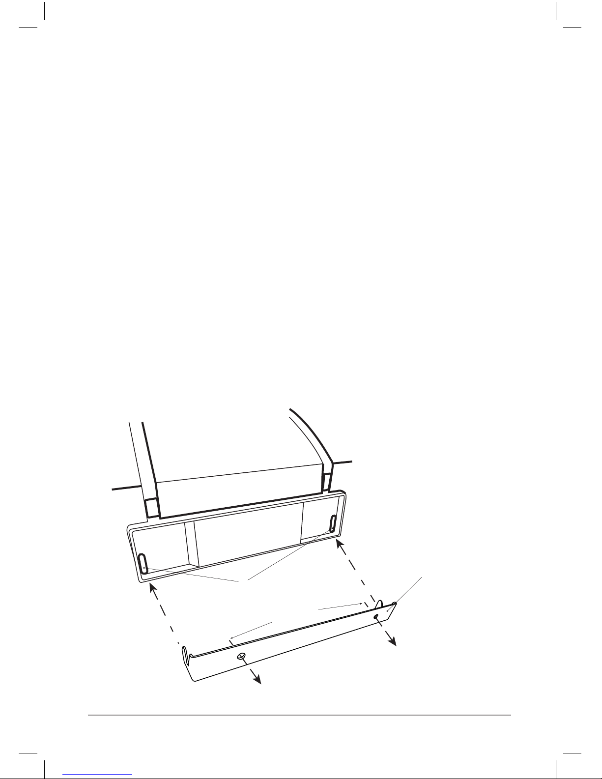
Please ensure that bracket xings
and the wall are adequate to support
the unit when full.
Bracket (supplied)
‘Punch through’ slots for
bracket ‘hooks’
Screw to wall
1. The Zip Varipoint II must be installed vertically. The connections should be at the rear
of the unit. When facing the heater the hot supply (red) is to the left and the cold supply
(blue) is to the right.
2. The heater may be mounted above or below the intended outlets providing the
water connections for the undersink models are at the top and for the oversink
models underneath.
NB. Undersink and oversink models are not interchangeable.
The xings must be capable of supporting the heater when full of water (see Technical
data page 5).
3. The undersink unit can be placed unsupported on the floor or cupboard base, but if
additional support is required, securing screws are supplied that locate to the rear
of the casing. [As shown in (fig.1)]
4. Always position the Zip Varipoint II to allow for its removal for future inspection and
maintenance.
5. The Zip Varipoint II is not recommended for installation above false ceilings.
6. Do not install in a location where this unit or connecting pipelines can freeze.
7. When considering the location of the heater, consideration should be given to the safe
and visible disposal of any water resulting from leaks and seepage.
This is particularly relevant when the heater is located in a roof space , cupboard or any
concealed location. For guidance please call Zip Customer Service on 0845 6 005 005.
Wall Mounting
g. 1
Positioning
Page 11

Instructions. V1.01 Page 9 October / 2013
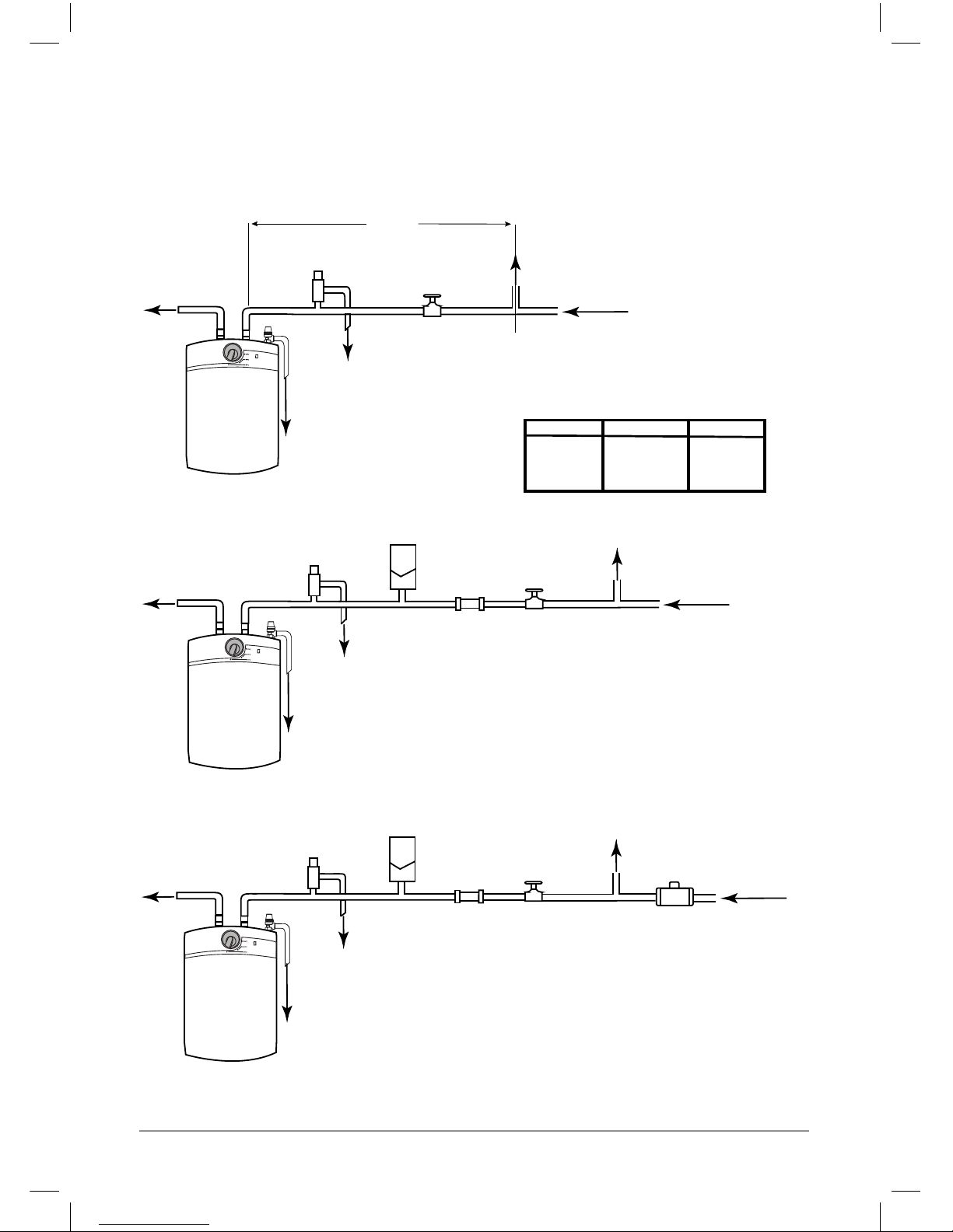
1. Check the incoming water supply pressure with reference to the table and diagrams on
the following page to determine the layout required bearing in mind that mains water
supply pressure can increase considerably at night.
2. Refer to the diagrams in (g.2) to determine the accessories required to suit your layout
3. Position the heater and controls to allow for future maintenance.
4. All control and safety valves are marked with the direction of ow and will not function if
incorrectly orientated. Do not break any seals or attempt to adjust any safety valve, to do
so may impair the safety of the installation and will invalidate the warranty.
5. To ensure a watertight seal use bre washers for connecting the inlet and outlet pipes to
the heater. Complete the seal by using PTFE tape to the threads but do not over apply or
extend beyond the thread limits as this will lessen the effectiveness of the joints. Do not
use plumbers paste to secure the joints as this can impair the operation of any valves
connected to the heater.
6. An isolating service valve (not supplied) should be tted in the cold water supply pipe
work as shown in all 3 diagrams in (g.2).
7. Flush all pipe work thoroughly before making the nal connections to the valves,
accessories and cold feed to the heater to ensure that any debris is removed. Failure to
do this may result in irreparable damage to the controls and will invalidate the warranty.
Plumbing and safety control arrangement
The unit will be supported by being hung on a bracket xed to a support wall, as
shown (g.1). Therefore it is important to ensure that the wall is strong and solid
enough to fully support the unit when the tank is full.
It is important to ensure when drilling the wall, that the selected position avoids any
pipe work or electrical cabling. To mount the heater, the bracket ‘hooks’ locate into
the slots provided in the back of the unit, allowing the unit to hang at against the
wall.
IT IS NOT NECESSARY TO REMOVE THE CASING TO MOUNT
THE WATER HEATER ON THE WALL BRACKET.
Page 12
Instructions. V1.01 Page 10 October / 2013
HOT COLD
EXPANSION
RELIEF VALVE
SERVICE VALVE
TO DRAIN
VIA TUNDISH
COLD WATER
SUPPLY
NEAREST
COLD WATER
DRAW OFF
DIAGRAM 1.
Inlet pressure less than 0.35 MPa (3.5 bar)
and expanded hot water can be accommodated
in the pipework.
HOT COLD
EXPANSION
RELIEF VALVE
EXPANSION VESSEL
SERVICE VALVE
CHECK VALVE
DIAGRAM 2.
Inlet pressure less than 0.35 MPa (3.5 bar)
and expanded hot water cannot be accommodated
in the pipework. (using pack AQ2 expansion vessel
and check valve).
COLD WATER
SUPPLY
TO DRAIN
VIA TUNDISH
NEAREST
COLD WATER
DRAW OFF
HOT COLD
EXPANSION
RELIEF VALVE
EXPANSION VESSEL
SERVICE VALVE
CHECK VALVE
PRESSURE REDUCING
VALVE
DIAGRAM 3.
Inlet pressure greater than 0.35 MPa (3.5 bar).
(Using pack AQ2 and AQ3 expansion vessel, check
valve and pressure reducing valve).
COLD WATER
SUPPLY
TO DRAIN
VIA TUNDISH
PRESSURE & TEMPERATURE
VALVE TO BE DRAINED VIA TUNDISH
Length ‘A’
COLD WATER
DRAW OFF
Minimum length of pipe (Length ‘A’ ).
5 Litres 1.2m (4ft) 0.6m (2ft)
10 Litres 2.7m (9ft) 1.2m (4ft)
15 Litres 4.2m (14ft) 1.8m (6ft)
SIZE 15mm Pipe 22mm Pipe
ZIP Varipoint II
ZIP Varipoint II
ZIP Varipoint II
PRESSURE & TEMPERATURE
VALVE TO BE DRAINED VIA TUNDISH
PRESSURE & TEMPERATURE
VALVE TO BE DRAINED VIA TUNDISH
g.2
(Underbasin model shown)
Installation diagrams
Page 13
Instructions. V1.01 Page 11 October / 2013
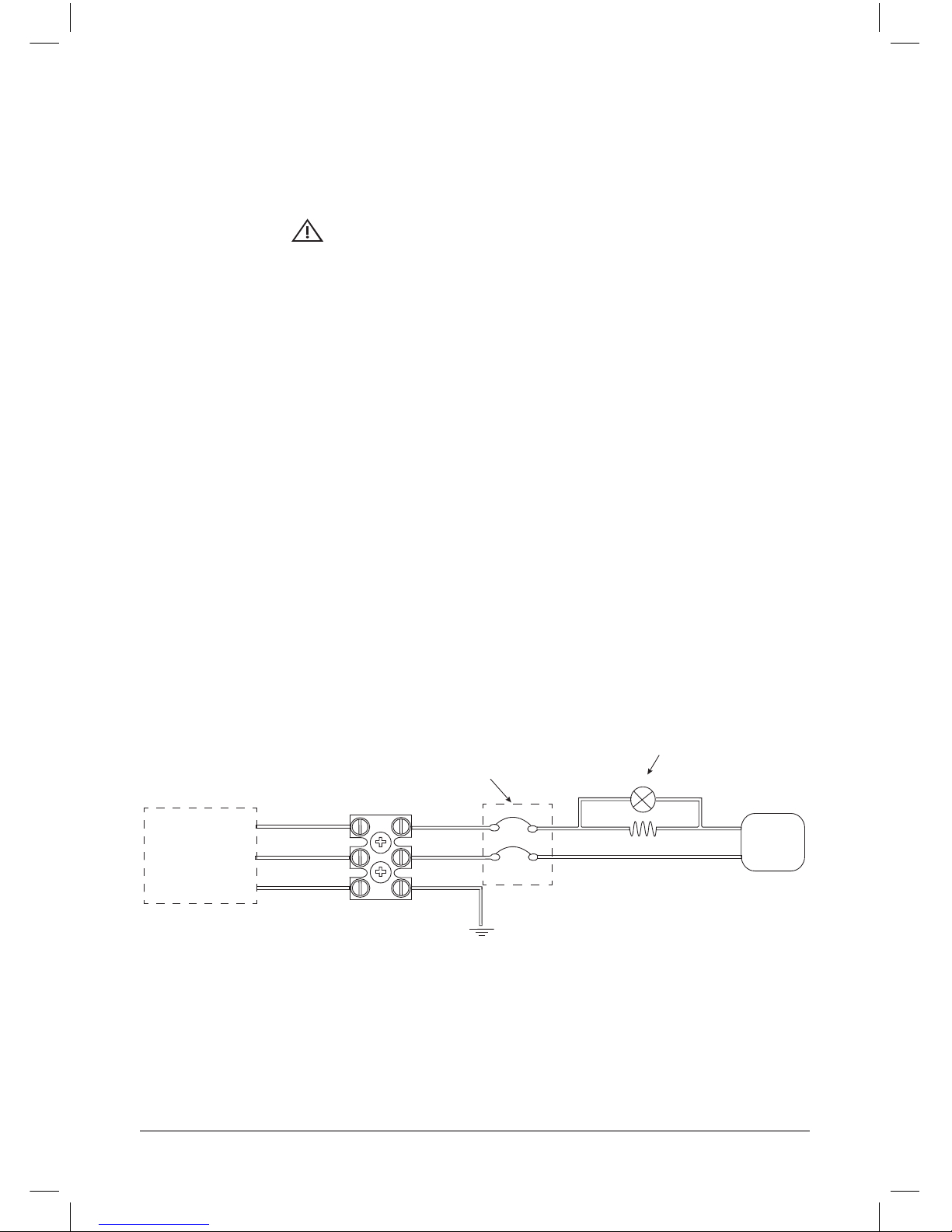
1. The Zip Varipoint is pre-wired with a length of 3 core cable suitable for connection to a
mains 230v supply. Connection must be made in accordance with the current IEE wiring
regulations to a double pole isolating switch on a dedicated circuit or a double pole
switched spur.
2. If the cable length is insufcient it is recommended that the entire length of cable is
replaced with no joins to the original. To replace the cable:
a. Prise the temperature control knob off the spindle and release the screw underneath
b. Remove the cover by sliding the it forwards, then remove.
c. Disconnect the cable from the connector block and remove it.
d. Pass the new cable back through the entry port and locking maze, then connect the
cable to the connector block.
e. Slide the cover back on and screw into position ensuring the cable is clamped correctly.
f. Replace the control knob.
3. All internal connections are factory wired and should not be altered or modied.
This appliance must be earthed.
Do not switch on the electrical supply until the water heater is full of water.
Electrical installation & wiring
It is recommended that the electrical installation is carried out by a qualied electrician.
It is essential that the electrical installation including earthing and cross bonding should
be carried out to comply with the current IEE regulations and local council requirements.
WARNING: SWITCH OFF THE MAINS ELECTRICAL SUPPLY
BEFORE CARRYING OUT ANY WORK INVOLVING A LIVE CIRCUIT.
230v AC SUPPLY ONLY, THIS APPLIANCE MUST BE EARTHED.
Safety Cut-out
In the event of a malfunction that leads to an over temperature situation, a Safety cut out
will automatically cut off the electrical supply to the element.
This is a manually resettable cut-out that may be reset by a qualied electrician once the
fault has been corrected.
Wiring Diagram
BROWN
BLUE
GREEN/YELLOW
LIVE
NEUTRAL
THERMOSTAT
NEON
INDICATOR BULB
EARTH
Supply through a
Fused doublepole
switch or fused
spur.
OVER TEMPERATURE
SAFETY CUT-OUT
Page 14
Instructions. V1.01 Page 12 October / 2013
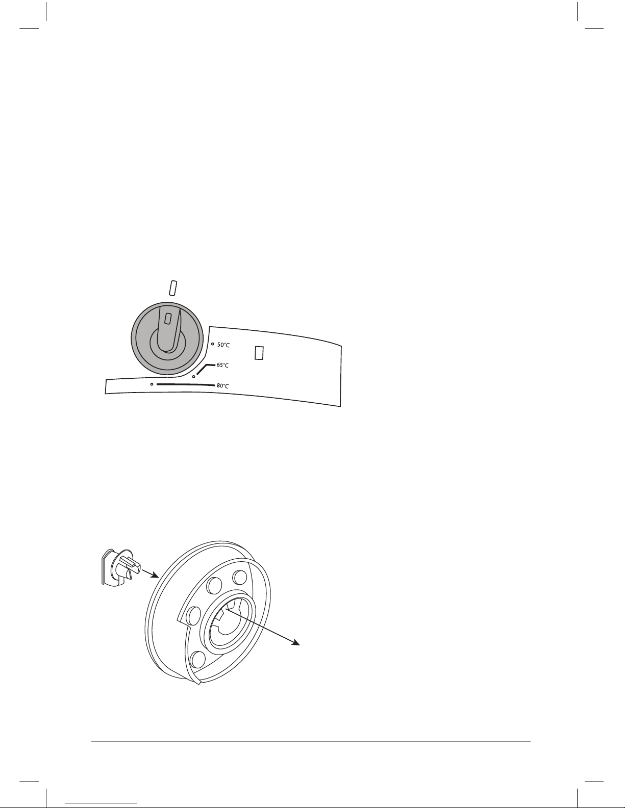
80
65
50
Temperature Limitation
a. Turn the temperature selector to the position
shown in fig.3 and then pull the
selector from the spindle.
b. Press out the small manual
insert from the inside of the
selector and refit in the
required maximum position.
( 50°, 65° or 80°).
c. Refit the temperature selector
on to the spindle.
(The temperature cannot now be set
to a value higher that that fixed
on the selector).
g.4
Commissioning & Operation.
1. Check that all ‘Installation Requirements’ have been met.
2. Check that all water and electrical connections are correct and tight.
3. Open a hot water tap.
4. Open the water mains isolating valve and allow the heater to ll.
5. Close the hot water tap when water starts to ow from it.(The heater vessel should now
be full).
6. Check for leaks and rectify as necessary.
7. Manually operate the ‘Expansion Relief Valve’ to ensure free water ow through the
discharge pipe by turning the knob to the left and holding it in the open position.
8. Set the temperature control knob to the required position. The position with a water
temperature of 50°C is recommended for economical operation while minimising limescale deposits and thermal losses.
This setting protects the appliance against frost damage,
but this protection does not extend to the connecting
pipework and fittings.
50°C - Economy setting
65°C - Standard Setting
80°C - Setting for very hot water
when large amounts of warm water
(hot & cold mixed) are required.
NB.The water heater cannot be switched off via the temperature selector.
It can only be switched off at the isolating switched mains supply socket.
ZIP Varipoint II
g.3
Page 15

Instructions. V1.01 Page 13 October / 2013
9. Switch on the electrical supply to the unit. The red neon light will glow during the heating
cycle and will extinguish when the selected temperature is reached re-lighting again for
the next heating cycle.
10. During the heating cycle no water should escape to waste from either the expansion
relief or T&P valves.
11. Allow the heater to reach the selected temperature and when the indicator light has
extinguished, check the water temperature and re-check the water connections
adjusting as necessary.
12. Please pass these instructions on the person responsible for the building and it’s
management.
Maintenance
Precautions.
1. The Zip Varipoint II is an unvented electric water heater and only a competent person
(electrician or plumber), familiar with unvented systems, should carry out any servicing
and maintenance work on this unit
2. WARNING When the neon indicator light is extinguished the unit is still connected
to the electricity supply, only by operating the ‘double pole isolating switch’ can the unit
be dis-connected from the supply.
3. The over temperature safety cut-out reset is located inside the cover. DO NOT reset the
over temperature cut-out until the cause of it’s operation has been correctly diagnosed
and corrected.
4. DO NOT use the water heater if it is suspected of being frozen. Switch off the electricity
supply if water ceases to ow and do not switch it back on until a competent person
(electrician or plumber), has checked that it is safe to do so.
5. The heater should be visually inspected regularly. This is particularly important if the
heater is located in a cupboard, roof space or any other concealed location. If there are
any signs of leaks or seepage the heater should be isolated from the water supply and
switched off from the electrical supply until a competent person (electrician or plumber),
has investigated the cause.
6. DO NOT block or restrict the discharge from any safety valve.
7. DO NOT tamper with any safety valve.
8. If water discharges from any safety valve, switch off the electrical supply to the unit, isolate the water supply and contact a competent person (electrician or plumber) familiar
with unvented systems.
9. Please note that lime scale forms more readily at higher temperatures. Damage or
failures caused by the formation of lime scale are specically excluded under the
terms of the warranty. To reduce lime scale formation to a minimum the unit should
always be operated at the lowest convenient temperature. The ‘50°C’ temperature
setting is recommended.
Page 16

Instructions. V1.01 Page 14 October / 2013
Schedule
It is recommended that all key components of the heater system should be inspected
on a regular basis, no greater than 12 monthly intervals, for the continued safe and
efcient operation of the unit. The inspection should be carried out by a competent
person (electrician or plumber) familiar with unvented systems and the components to
be inspected should include the following:
1. Expansion relief valve. Check correct operation.
2. T&P relief valve, if tted. Check correct operation.
3. Expansion vessel, if tted. Check pressure-referring to label on the side of the vessel.
4. Integral line strainer, if a pressure reducing valve is tted. Inspect and clean as
necessary.
5. Check the discharge pipe is free of obstructions.
6. Check that all the electrical connections are tight.
De-Installation
• Switch off and disconnect the electrical supply.
• Close the mains water supply isolating valve.
• Disconnect the inlet and outlet connections on the heater.
• Remove the heater.
• Drain the unit through the hot water supply connection.
Page 17
Instructions. V1.01 Page 15 October / 2013
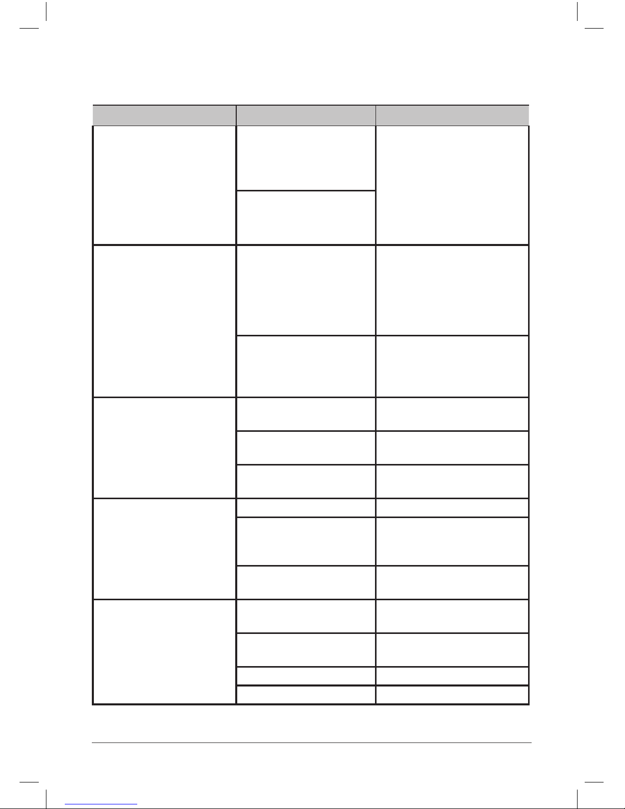
Fault Possible cause Solution
Over temperature cut-out
operates.
The thermostat has failed.
Reset and if the cut-out operates again, isolate the unit and
contact the installer.
NB. Isolate the electrical
supply before removing the
cover and ensure that the
cover is correctly replaced and
secured before reconnecting.
The thermostat is set at too
high a temperature.
Regular, intermittent water
discharge from the tundish.
Loss of pressure from the
expansion vessel.
Isolate the heating system and
the mains cold water supply.
Partly drain the unit. Recharge
the expansion vessel to the
specied pressure and re-
commission.
Thermostat failure.
Isolate the heating system and
check the thermal controls
when discharge ceases. Replace
the thermostat if faulty.
Continuous water discharge
from tundish.
Pressure reducing valve not
operating correctly.
Check with pressure gauge and
replace as necessary.
T&P relief valve not operating correctly.
Check and replace if faulty.
Expansion relief valve not
operating correctly.
Check and replace if faulty.
No water ow from hot taps.
Cold water mains is isolated.
Check and switch on.
Integral line strainer in
pressure reducing valve is
blocked.
Check and clean as necessary.
Pressure reducing valve is
incorrectly fitted.
Ret correctly with arrows in the
direction of ow.
Water from hot taps is cold.
Power supply not switched
on
Check and switch on.
Over temperature cut-out
has operated.
See fault ‘Over temperature cutout operates’ above.
Faulty element.
Check and replace as necessary.
Thermostat failure.
Check and replace as necessary.
Fault Finding
Page 18

Instructions. V1.01 Page 16 October / 2013
The Zip appliance you have chosen is precision-built from the nest materials available and
should give many years of trouble free service.
Certain warranties may be implied by law into your contract with Zip.
The
warranty provided below is additional to these implied warranties and
nothing
set out
below shall limit your statutory rights or rights at law.
Zip Heaters (UK) Ltd warrants that, should any part fail within 12
calendar
months of
installation, that part will be repaired or replaced free of charge by
Zip or its Distributor or
Service Provider, except as set out below, provided
the
appliance is installed and used strictly
in accordance with the
instructions
supplied, and that failure is not due to accident, misuse,
abuse,
unsuitable
water conditions, or to any alteration, modication or repair by any party
not
expressly nominated by
Zip.
No costs are payable by the customer other than any mileage or
travelling-time
charges
incurred by a Zip Service Provider or the cost of removal, cartage
and
re-installation of any
component of the appliance if it needs to be returned
for
repair to Zip or its Distributor.
This warranty does not cover damage resulting from non-operation of
the
appliance or
consequential damage to any other goods, furnishings or property.
Zip does not exclude, restrict or modify any liability that cannot be
excluded,
restricted or
modied or which cannot, except to a limited extent, be
excluded,
restricted or modied as
between the owner or user and Zip under the
laws
applicable.
Furthermore, this warranty does not displace any statutory warranty, but, to
the
extent to
which Zip is entitled to do so, the liability of Zip under any
statutory
warranty will be limited
at Zip’s option to the replacement of the appliance
or
supply of equivalent appliance, the
payment of the cost of replacing
the
appliance or acquiring an equivalent appliance, or the
payment of the cost of having the appliance repaired or the repair of the
appliance.
Warranty
NOTE: It is our policy to continually improve products and as such we reserve the right to alter
data, specications and component parts without prior notice.
To ensure you have the latest revision of this instruction manual, please visit www.zipheaters.co.uk
to download the latest copy.
IMPORTANT: No liability is accepted for incorrect use of this product.
 Loading...