

Zip Heaters P4/52, P4/52UB, P4/102, P4/102UB, C2/50 Installation, Maintenance And User Instructions
...
Zip Tudor II & Contract II
Point of use Water Heaters
Models: P4/52, P4/52UB, P4/102,
P4/102UB. C2/50, C2/100, C3/50.
Installation, Maintenance and User Instructions
Please read these instructions carefully before commencing installation of the water heater.
Please leave these instructions with the end user after installation.
Zip Heaters (UK) Ltd
14 Bertie Ward Way
Dereham
Norfolk
NR19 1TE
Telephone: 0845 6 005 005
Fax: 01362 692448
Web: www.zipheaters.co.uk
The term ‘Zip’
is a registered trademark
Issued JUNE 2013 V1.01
Instructions. V1.01 Page 1 JUNE / 2013
Contents 1
Approvals 1
Description 2
WARNINGS
3
CAUTIONS
4
Packed Contents 4
Accessories 4
Technical Data 5
Spare Parts 6
Installation 7
Requirements 7
Wall Mounting 7
Overbasin Installation 8
Underbasin Installation 8
Electrical Installation 9
Cable installation/replacement 9
Safety Cut Out 10
Commissioning & Operation 11
Warranty 12
Please read these instructions carefully before commencing installation of the Point of Use
Water Heater.
Please leave these instructions with the end user after installation. To ensure you have a copy
of the latest instructions visit www.zipheaters.co.uk
Approvals
The Zip Tudor II and Contract II models are approved to the LVD and EMC directives and CE
endorsed.
The Zip Tudor II and Contract II models have been examined, tested and found when correctly
tted to comply with the requirements of the United Kingdom Water Regulations / Byelaws
(Scotland). The products are listed under the WRAS (Water Regulations Advisory Scheme)
Water Fittings and Materials Directory.

Instructions. V1.01 Page 2 JUNE / 2013
These instructions refer to the following models:
TUDOR II LOADING INSTALLATION
5 LITRE MODELS: P4/52, P4/52UB 1.8kW/230V Overbasin/Underbasin
10 LITRE MODEL : P4/102, P4/102UB 1.8kW/230V Overbasin/Underbasin
CONTRACT II
5 LITRE MODELS: C2/50, C3/50 1.8kW/230V Overbasin
10 LITRE MODEL : C2/100 1.8kW/230V Overbasin
Description
The Zip Tudor II and Contract II models are SINGLE point-of-use open outlet water heaters.
Being displacement type water heaters the hot water ow is controlled by the rate at which
cold water enters the vessel.
They can be connected either to the cold water main or fed from an overhead cold water
cistern (minimum head 3 metres).
Being fully automatic the Tudor II and Contract II may be left switched on under the control
of the thermostat, however WARNING This means that the unit remains potentially ‘LIVE’
when the selector is set to ‘0’. The unit can only be switched off (isolated) by operating the
double pole isolating switch to isolate the heater unit from the power supply.
The stored hot water is delivered from an open outlet spout (supplied with overbasin models)
or a Zip approved open outlet vented tap. This type of tting is permanently open to the
atmosphere which allows the expansion of water, that occurs during the heating cycle, to be
safely discharged.
During the heating cycle, drips will form and fall from the delivery spout or tap and these will
cease when the cycle has been completed and the stored water temperature has reached the
level set by the user. The higher the temperature selected the greater the rate of expansion.
Overtightening of the inlet water control valve or tap will not prevent the drips that occur, but
may cause damage to the valve or tap.
Temperature Control
The operating temperature range is 35-80°C. To protect the water heater against frost the
temperature control setting may be positioned at ‘ ‘ when a stored water temperature
of 5°C will be maintained. NOTE -the protection does not extend to connecting pipework or
ttings.
The economy setting ‘E’ will maintain the stored water temperature at approximately 60°C.
At the ‘E’ setting the temperature control locates into a set position and slight resistance will
be felt when rotating the temperature control beyond this setting. This is a safety measure to
ensure that higher temperatures are deliberately selected.
Neon Lamp (Tudor II and C3/50 models)
The Neon lamp will glow while the elements are in operation but will extinguish when the
chosen temperature has been reached. CAUTION: The unit will remain ‘LIVE’ when the
neon lamp does not glow.
Once installed DO NOT remove the cover under any circumstances without rst isolating the
electrical supply to the heater.

Instructions. V1.01 Page 3 JUNE / 2013
WARNINGS
• Installation, commissioning and maintenance of this appliance must only be carried
out by a competent installer who will then be responsible for adhering to all relevant
standards and regulations.
• The appliance must be disconnected from mains power supply before carrying out
any work involving live circuits.
• The appliance must be permanently connected to the supply through an isolating switch
with a contact separation of at least 3mm in all poles and be protected by a suitably rated
RCD.
• To protect the appliance, an MCB (miniature circuit breaker) or cartridge fuse must be
tted with a rating suitable for the nomi nal current of the appliance.
• The cross sectional area of the connection cable must be appropriate for the power rating
and location of the appliance. See Technical Data.
• The connecting cable must be adequately secured.
• This appliance must be earthed at all times.
• Check that the power supply is switched off prior to electrical connection.
• The appliance, its wiring and piping must not be modied in any way.
• In case of malfunction isolate the power supply immediately. In case of leaks also isolate
the water supply. Repairs must only be carried out by Zip Heaters (UK) Ltd or an authorised
Zip service engineer.
• Temperatures in excess of approximately 43°C are perceived as hot, especially by children,
and may cause a feeling of burning.
• This appliance must not be used by any person (inclu ding children) with limited physical,
sensorial or mental abilities or failing experience and/or knowledge unless they are
supervised by a person responsible for their safety or have received instructions about
how to use the appliance.
WARNING: Situations that could cause injury to yourself or others.
CAUTION: Situations that could cause damage to your appliance or other equipment.
NOTE: Notes, usage tips or additional information.
IMPORTANT:
PLEASE READ THESE INSTRUCTIONS CAREFULLY.
NOTE THE SAFE OPERATIONAL REQUIREMENTS, WARNINGS AND CAUTIONS. USE THIS PRODUCT
CORRECTLY AND WITH CARE FOR THE PURPOSE FOR WHICH IT IS INTENDED. FAILURE TO DO
SO MAY CAUSE DAMAGE AND/OR PERSONAL INJURY, AND WILL INVALIDATE THE WARRANTY.
RETAIN THESE INSTRUCTIONS FOR FUTURE USE.
Possible New Statement

Instructions. V1.01 Page 4 JUNE / 2013
CAUTIONS
• Children should be supervised in order to make sure that they do not play with the appliance.
• The water vessel is intended for an open outlet and should never be subject to greater
than atmospheric pressure.
• The inlet control valve should not be subject to pressure exceeding 0.35 MPa (3.5bar).
• The appliance must only be used when correctly installed and in perfect working order.
• The appliance must be installed in a frost-free room and must never be exposed to frost.
• The appliance must be completely lled with water before being switched on.
• THE HOT WATER SHOULD BE DELIVERED FROM THE OPEN OUTLET SPOUT SUPPLIED OR A
ZIP APPROVED OPEN OUTLET TAP FITTING THAT REMAINS PERMANENTLY OPEN TO ALLOW
FOR EXPANSION THAT OCCURS DURING THE HEATING CYCLE. UNDER NO CIRCUMSTANCES
SHOULD THE SPOUT OR OUTLET BE CONNECTED TO A TAP WHICH IS CAPABLE OF BEING
CLOSED.
• The Zip Tudor II and Contract II is intended for connection to mains supply only. In any other
case please contact Zip on 0845 6 005 005 for advice.
• Zip Heaters (UK) Ltd cannot be held liable for any damages caused by failure to
observe these instructions.
• It is recommended that an HE45004 Water Block is tted in the water supply line to
minimise the potential damage in the event of any leakage.
Packed Contents:
Please check that the items below have been supplied in the Heater Unit package.
Outlet Spout x1(except UB models)
Wall Bracket x1
Control Valve x1 (except UB models)
Fixing Screws x2
Rawlplugs x2
Accessories:
Only Zip approved open outlet accessories should be used, the following are available.
HE45004 Water Block (for both overbasin and underbasin models)
Overbasin TS/1 Telescopic Spout 350-600mm.
Underbasin UB/1 Monobloc Mixer Tap.
UB/6 Single Lever Basin Tap.
UB/7 Single Lever Sink Tap.

Instructions. V1.01 Page 5 JUNE / 2013
Technical data
Model Tudor II and Contract II models
Nominal supply voltage 1/N/PE 230V~
Power rating (kW) 1.8
Rated Current (A) 7.8
Element type Embedded Rod
Maximum supply pressure 0.35MPa (3.5 bar)*
Temp. Adjustment range 35°C~80°C
Capacity 5 Litre 10 Litre
Dimensions H x W x D (mm) 390x255x215 440x310x265
Minimum weight (kg) (Empty) 3.5 4.0
Maximum weight (kg) (Full)) 8.5 14.0
Rated volume (litres) 5 10
Water connections (BSP) 1/2”
Protection class IP24
All data quoted at nominal supply voltage.
For higher supply pressures it is recommended that a Zip AQ3 (set at 3.5 bar) pressure reducing
valve is used.
ZIP Tudor II
ZIP
CONTRACT
W
D
H
D
W
H
C3/50Tudor II, C2/50 and C2/100
NOTE:
Overbasin and underbasin models are NOT interchangeable. For underbasin applications use
models designated ‘UB’ and use only Zip approved vented tap accessories.

Instructions. V1.01 Page 6 JUNE / 2013
ITEM Description PART No. P4 MODELS C2 MODELS C3 MODEL
1 Heating element CTO111/4 X X X
2 Element gasket CTO116/4 X X X
3 Fascia CT0130 X
3 Fascia (OB) CT0107/3 X
3 Fascia (UB) CT0108/3 X
4 Thermostat CT0119/4 X X X
5 Re-settable cut-out CT0121/4 X
5 Re-settable cut-out CT0122 X
5a Thermal fuse CT0120 X
6 Neon light indicator CT0129/4 X X
7 Retaining nut CT0115/4 X X X
8 Front cover (5L) CT0103/3 X
8 Front cover. OB (5L) CT0123 X
8 Front cover. UB (5L) CT0124 X
8 Front cover (5L) CT0125 X
9 Back cover (5L) CT0101/3 X X X
8 Front cover (10L) CT0105/4 X X
9 Back cover (10L) CT0102/3 X X
10 Outlet Spout CT0137 X(OB) X X
11 Control valve CT0138 X(OB) X X
12 Control knob with spring CT0106/3 X X X
Spare Parts
9
8
1
5
4
2
7
6
5a
11
10
3
ZIP TUDOR II
12

Instructions. V1.01 Page 7 JUNE / 2013
Installation.
Requirements.
• Before starting installation the WARNINGS (page 3) and CAUTIONS (page 4)
should be read and fully understood.
• It is recommended that the piping and water connection is carried out by a qualied
plumber.
• Thoroughly ush the water supply pipes before installation to remove any water borne
debris.
• The electrical installation including earthing and cross bonding should comply with current
IEE regulations and any Local Authority requirements.
• Zip Contract and Tudor water heaters must be installed according to the specication on
the rating plate and the technical specications.
• Take care to protect the wiring from damage during installation and ensure that any
uninsulated wiring is not directly accessible after installation.
• For maintenance work an isolating valve should be installed in the water supply line to
the heater.
• A minimum clearance of 270mm is required underneath the overbasin heater units and
above the underbasin units to allow for the removal of the element plate assembly and for
servicing purposes.
• When considering the location of the heater, consideration should be given to the safe and
visible disposal of any water resulting from leaks and seepage.
Wall Mounting.
The unit will be supported by being hung on a bracket xed to a support wall, using the
xings provided (as shown g.1).
Therefore it is important to ensure that the wall is strong and solid enough to fully support
the unit when full.
It is important to ensure when drilling the wall, that the selected position avoids any
pipework or electrical cabling.
To mount the heater, the bracket ‘hooks’ locate into the slots provided in the back of the
unit, allowing it to hang at against the wall.
IT IS NOT NECESSARY TO REMOVE THE CASING TO MOUNT THE
WATER HEATER ON THE WALL BRACKET.
g. 1

Instructions. V1.01 Page 8 JUNE / 2013
Overbasin Installation.
The inlet control valve supplied incorporates compression ttings suitable for tting
between 15mm copper piping (water supply) and the inlet connection (coloured blue)
situated on the water heater.
Fit the control valve to the cold water supply ensuring that the water will ow in the
direction of the arrow indicated on the side of the control valve (g.2a).
Do not over tighten the compression joints but ensure that these are leak free.
WATER
SUPPLY
ZIP Tudor II
g. 2
g. 2a
MAINS
Supply
ZIP
Tudor II
Cold (Supply In)
Hot to Tap
ZIP Approved
Vented Tap
Underbasin Installation.
In all underbasin installations the outlet must be connected to an open outlet type
fitting approved by Zip heaters.
The diagram below (fig 3) shows a typical installation of a monobloc mixer tap
assembly, product ref. UB1. Alternative Zip approved products are product ref. UB6
and UB7.
NOTE:
When installing underbasin models it is recommended that bre washers are used on
both inlet and outlet connections to ensure a watertight seal.
Connect mains supply to the ‘blue’ tag tail (arrow pointing UPWARD). The inlet ‘blue’
connection on the heater is connected to the ‘blue’ tag tail (arrow pointing DOWNWARD).
The outlet connection of the heater ‘red’ is connected to the ‘red’ tag tail (arrow pointing
UPWARD).
g.3
Instructions. V1.01 Page 9 JUNE / 2013
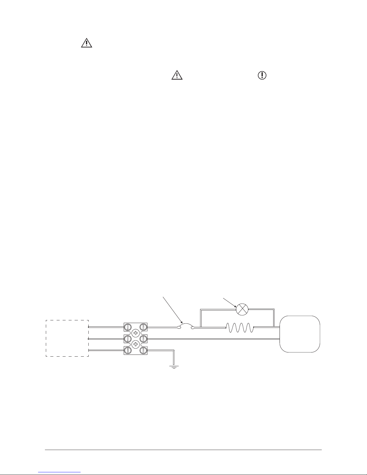
BROWN
BLUE
GREEN/YELLOW
RED
BLACK
HEATING ELEMENT
THERMOSTAT
NEON
INDICATOR BULB
EARTH
Supply through a
Fused doublepole
switch or fused
spur.
Tudor II and C3/50 models.
OVER TEMPERATURE
SAFETY CUT OUT
Electrical Installation.
WARNING: SWITCH OFF THE MAINS ELECTRICAL SUPPLY BEFORE CARRYING OUT
ANY WORK INVOLVING A LIVE CIRCUIT. 230v AC SUPPLY ONLY, THIS APPLIANCE MUST BE
EARTHED.
Before starting installation the WARNINGS (page 3) and CAUTIONS (page 4) should be
read and fully understood.
It is recommended that the electrical installation is carried out by a qualied electrician.
g.4
NB. Tudor II .
The Tudor models all come pre-wired with a 1 metre length of cable.
If in the lifetime of the unit the cable is damaged or a greater length of cable is required then
to replace the supply cable, refer to the following ‘Cable installation/replacement’
instructions.
Cable installation/replacement ( Tudor II and Contract II ).
First remove the temperature adjustment selector switch and release the screw located
beneath.
Unscrew the four cover screws-two on the top and two on the bottom of the unit, this will
then allow the outer cover to be removed.
The supply cable should have a nominal cross section of not less than 1.5mm².
The supply cable enters the casing through a cable clamp located in the rear casing cover
Make the connections in the terminal block provided as indicated in (g.4), then after ensuring
that the cable is rmly clamped, replace the front casing, cover and selector switch.

Instructions. V1.01 Page 10 JUNE / 2013
Models P4/52,P4/52UB, P4/102, P4/102UB
A manually resettable cut out that may be reset by a qualied electrician once the fault has
been corrected
Models C2/50, C2/100
A thermal fuse which should be replaced by a qualied electrician.
Model C3/50
An automatically ressttable cut out, reset by simply switching off the electrical supply to the
unit for at least 2 minutes.
When power is restored the cut out will have reset. However if the fault persists then the unit
should be isolated from the power supply and fault nding be carried out by a qualied
engineer.
Safety Cut Out.
In the event of a malfunction that leads to an over temperature situation, a safety cut out will
automatically cut off the electrical supply to the element (refer g.4).
The cut out and reset operations for the various models are described below.
Instructions. V1.01 Page 11 JUNE / 2013
Commissioning & Operation.
DO NOT SWITCH ON THE HEATER UNTIL IT IS FILLED WITH WATER
Open the inlet control valve or tap to allow the tank to ll with water, the tank will be full
when water begins to run continuously from the spout or tap.
Close the inlet control valve or tap and switch on the electrical supply, adjusting the temperature
control to the required level.
The contents of the water vessel will be heated to the selected temperature.
NB. During the heating cycle expansion will take place and water will drip from the spout
or tap. This will cease when the operating temperature has been reached, (approx 9
mins/+50°C for the 5L models, approx. 18 mins/+ 50°C for the 10L model).
Therefore always ensure that the spout outlet is positioned over the basin.
Hot water is drawn off by opening the inlet control valve or tap, this allows cold water to
enter the storage vessel as the heated water is displaced and is owing out.
Safety Warning.
Under no circumstances is the water heater to be used if suspected of being frozen.
If water ceases to ow switch off the electrical supply immediately at the isolating switch.
It is then recommended that a qualied Plumber/Electrician checks the unit.
Any water can be drained via the cold inlet connection whilst in the original location.
To remove the outer case, prise off the temperature selector switch and release the screw
located beneath it.
Remove the four front cover securing screws at the top and bottom of the unit, the outer case
can now be lifted off.
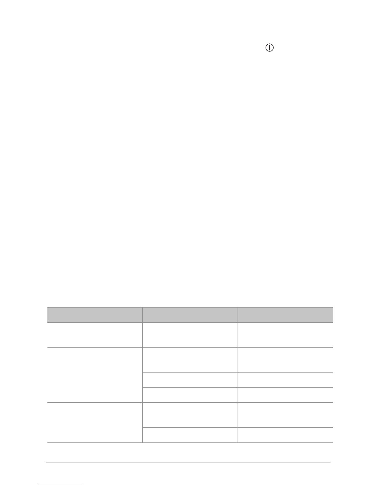
Maintenance.
Very little maintenance is required, however it is recommended that the replacement of spare
parts is carried out by a relevant competent person ie. Plumber or Electrician for any more
information please contact the Service Dept. ZIP HEATERS (UK) LTD TEL.0845 6 005 005.
Problem Possible cause Solution
NO WATER
MAINS WATER NOT TURNED
ON
CHECK SUPPLY AND TURN ON
NO HOT WATER
OVER TEMPERATURE CUT
OUT HAS OPERATED
REFER TO INSTRUCTIONS ON
PAGE 10.
FAULTY THERMOSTAT REPLACE THERMOSTAT
FAULTY ELEMENT REPLACE ELEMENT
WATER IS TOO HOT
THERMOSTAT IS SET TOO
HIGH
RESET THERMOSTAT
FAULTY THERMOSTAT REPLACE THERMOSTAT

Instructions. V1.01 Page 12 JUNE / 2013
The Zip appliance you have chosen is precision-built from the nest materials available and
should give many years of trouble free service.
Certain warranties may be implied by law into your contract with Zip.
The
warranty provided below is additional to these implied warranties and
nothing
set out
below shall limit your statutory rights or rights at law.
Zip Heaters (UK) Ltd warrants that, should any part fail within 12
calendar
months of
installation, that part will be repaired or replaced free of charge by
Zip or its Distributor or
Service Provider, except as set out below, provided
the
appliance is installed and used strictly
in accordance with the
instructions
supplied, and that failure is not due to accident, misuse,
abuse,
unsuitable
water conditions, or to any alteration, modication or repair by any party
not
expressly nominated by
Zip.
No costs are payable by the customer other than any mileage or
travelling-time
charges
incurred by a Zip Service Provider or the cost of removal, cartage
and
re-installation of any
component of the appliance if it needs to be returned
for
repair to Zip or its Distributor.
This warranty does not cover damage resulting from non-operation of
the
appliance or
consequential damage to any other goods, furnishings or property.
Zip does not exclude, restrict or modify any liability that cannot be
excluded,
restricted or
modied or which cannot, except to a limited extent, be
excluded,
restricted or modied as
between the owner or user and Zip under the
laws
applicable.
Furthermore, this warranty does not displace any statutory warranty, but, to
the
extent to
which Zip is entitled to do so, the liability of Zip under any
statutory
warranty will be limited
at Zip’s option to the replacement of the appliance
or
supply of equivalent appliance, the
payment of the cost of replacing
the
appliance or acquiring an equivalent appliance, or the
payment of the cost of having the appliance repaired or the repair of the
appliance.
Warranty
NOTE: It is our policy to continually improve products and as such we reserve the right to alter
data, specications and component parts without prior notice.
To ensure you have the latest revision of this instruction manual, please visit www.zipheaters.co.uk
to download the latest copy.
IMPORTANT: No liability is accepted for incorrect use of this product.
The use of this crossed out wheeled bin logo indicates that this product needs
to be disposed of separately to any other household waste.
Within each of the European Union member countries, provisions have been
made for the collection and recycling of unwanted electrical and electronic
equipment.
In order to preserve our environment we ask that you dispose of this product
correctly. Please contact Zip Customer Service for advice on 0845 6 005 005.
 Loading...