

Page 1
Installation and Operating Instructions
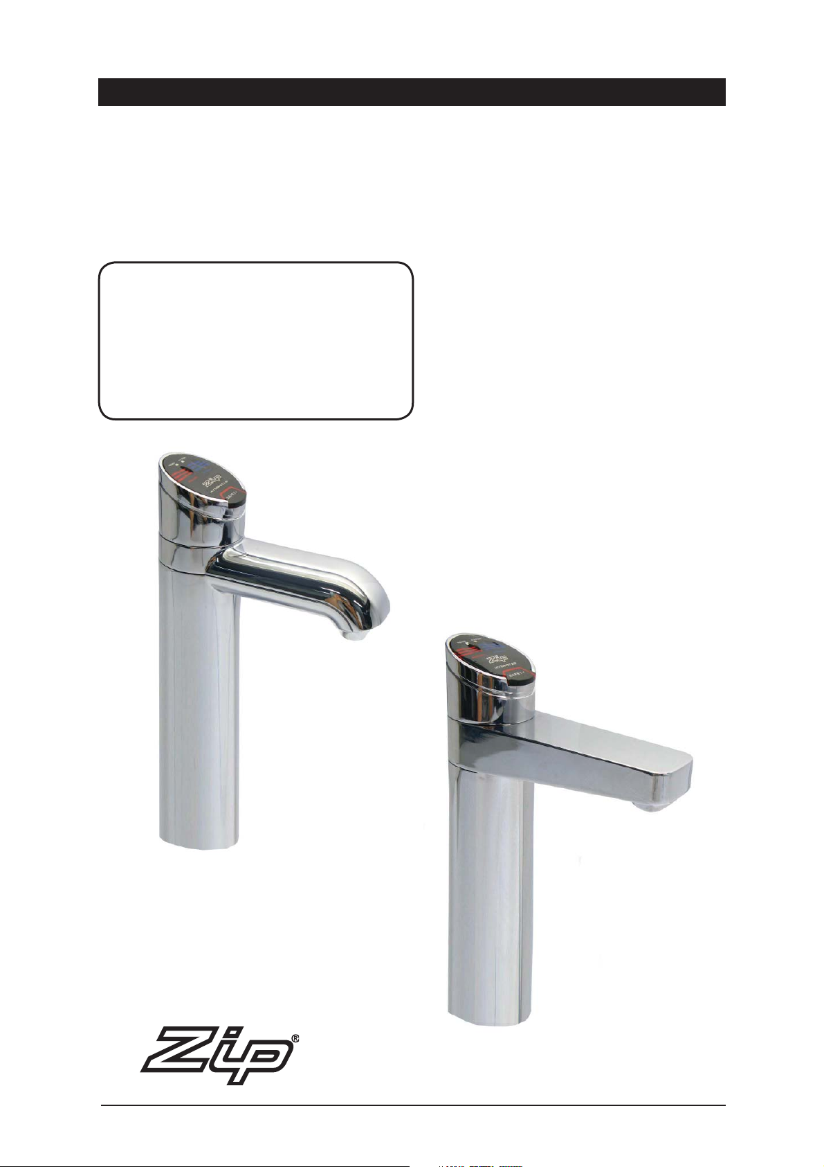
Zip HydroTap Miniboil
Boiling and Ambient drinking water for kitchens and the home.
Affix Model Number Label Here
89585UK
®
Page 1 of 16 Zip Hydro Tap Installation and Operating Instructions - 89585UK - June 2011 v1.01
Page 2

This page intentionally left blank
Zip Hydro Tap Installation and Operating Instructions - 89585UK - June 2011 v1.01 Page 2 of 16
Page 3

Check List
Before Installation:
A. Read the instructions
B. Note: Not all fittings are supplied with the appliance kit. Isolation valves are not supplied
C. The pressure limiting valve must be fitted as part of the kit.
D. Check the water quality to determine if extra filtration will be required.
E. Check the appliance rating plate and ensure correct power is available for the appliance.
F. Check the underbench cupboard supporting the appliance is adequate for the total weight of
the appliance, when full of water.
Before Commissioning:
1. Check the unit has been secured correctly.
2. Flush the supply line before connecting.
3. Check all plumbing fittings have been tightened.
4. Ensure the outlet and vent pipes are positioned to drain correctly.
5. For undersink units ensure there is adequate ventilation.
6. Check all tubes from the undersink unit to the tap, have a constant rise and there are no ‘S’
traps or kinks in the hoses.
7. Check all electrical connections are correct and there are no loose wires.
Commission:
8. Turn on the water and check for leaks.
9. Turn on the power.
10. Flush the filter for 3 - 5 minutes.
11. Allow sufficient time for the unit to heat up and fill, before using.
Page 3 of 16 Zip Hydro Tap Installation and Operating Instructions - 89585UK - June 2011 v1.01
Page 4

Contents
Read These Warnings First. . . . . . . . . . . . . . . . . . . . . . . . . . .5
Models Covered by these Instructions . . . . . . . . . . . . . . . . . . 6
Installation Requirements . . . . . . . . . . . . . . . . . . . . . . . . . . .6
Special Tools Required. . . . . . . . . . . . . . . . . . . . . . . . . . . . . . 7
Installation Procedure . . . . . . . . . . . . . . . . . . . . . . . . . . . . . . 7
Step A - Installing the tap . . . . . . . . . . . . . . . . . . . . .7
Step B - Installing the undersink unit . . . . . . . . . . . . 8
See special note page 8, ventilation buffers.
Step C - Installing the filter . . . . . . . . . . . . . . . . . . . . 8
Step D - Connecting the tap, . . . . . . . . . . . . . . . . . . . 9
Step E - Connecting the Water Supply . . . . . . . . . . . 9
Step F - Testing and commissioning . . . . . . . . . . . . .10
Operating the Tap . . . . . . . . . . . . . . . . . . . . . . . . . . . . . . . . .11
Font Installation Procedure . . . . . . . . . . . . . . . . . . . . . . . . . .12
Trouble Shooting . . . . . . . . . . . . . . . . . . . . . . . . . . . . . . . . . . 13
Cleaning . . . . . . . . . . . . . . . . . . . . . . . . . . . . . . . . . . . . . . . . 13
Warranty Information . . . . . . . . . . . . . . . . . . . . . . . . . . . . . . . 14
Notes. . . . . . . . . . . . . . . . . . . . . . . . . . . . . . . . . . . . . . . . . . . 15
NOTE:
Read all instructions and precautions before proceeding. If in doubt, or need
further guidance, please call Zip on 0845 602 4533.
Please leave these instructions with the end user after installation
This unit must be installed in accordance with water supply byelaws, current
IEE regulations and relevant local authority byelaws.
Zip Hydro Tap Installation and Operating Instructions - 89585UK - June 2011 v1.01 Page 4 of 16
Page 5
The power point must be located within
reach of its cable. The appliance must be
positioned so that the power point is
accessible.
Read These Warnings First
Safety
This appliance is not intended for use by persons (Including Children) with
reduced physical, sensory or mental capabilities, or lack of experience and
knowledge, unless they have been given supervision or instruction concerning
use of the appliance by a person responsible for their safety.
Children should be supervised to ensure they do not play with the appliance
Qualifications
If any power cord or plug is damaged it must be repaired only by a qualified
technician. To avoid hazards, all installation procedures must be carried out by
a suitably qualified trades person. The power cord and power outlet must be in
a safe visible position for connection.
Venting
Sometimes steam and / or boiling water may discharge through a vent outlet at
the mouth of the tap. If the tap is not installed using the Font pedestal, ensure
the tap body is located so the tap outlet safely drains into the sink bowl area.
Lifting
Take care when lifting the Zip HydroTap undersink unit. Some units may exceed
safe lifting limits. Do not lift without assistance. The weights of the units are
given in the table under the heading “Installation Requirements”.
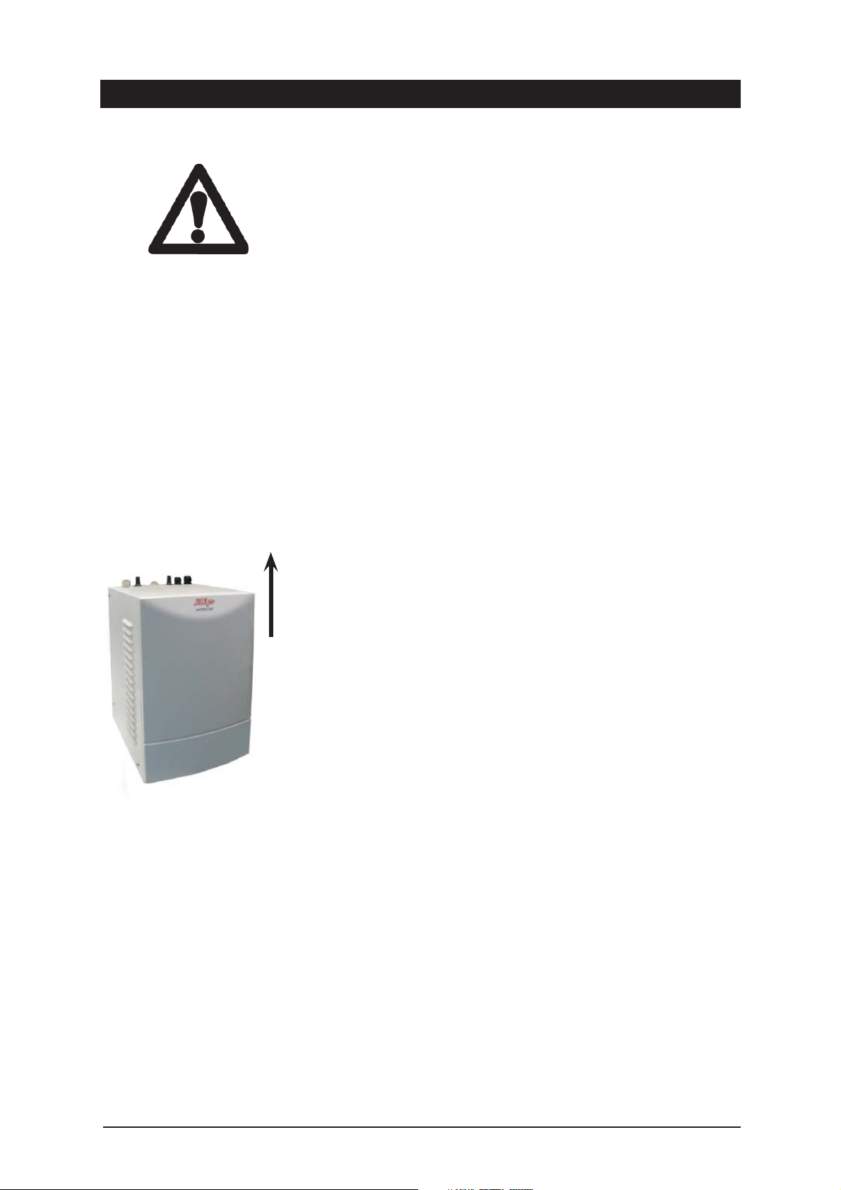
This way up
Zip Hydrotap undersink assembly.
The appliance must be placed on a horizontal
surface in an upright position, as shown above.
Airflow
The ambient temperatures this unit should operate within are 5ºC - 35ºC.
Proper air circulation must be provided. The system will operate satisfactorily
only if the recommended air gaps are provided, these are 65mm min rear
clearance and 50mm side clearance.
Included in the installation pack are
adhesive backed silicon buffers. If air vents are not installed in the cupboards
housing the HydroTap, the buffers must be placed on the inside edge of the
cupboard door to create a slight gap ensuring a minimum airflow. Failure to do
this may cause the HydroTap to overheat and operate inefficiently.
Note:
Always ensure the hoses are shortened so that any excess is removed
and their route is the most direct line between the tap assembly and the
HydroTap unit.
Do not allow the hoses to sag or droop so water is trapped within the
hoses.
Positioning of the tap assembly must be within the following parameters:
The height between the base of the Hydrotap unit and the base of the Tap
assembly cannot be greater than 900mm.
Page 5 of 16 Zip Hydro Tap Installation and Operating Instructions - 89585UK - June 2011 v1.01
Page 6
# Section Heading# Section Heading
Read these Warnings continued
Frost Protection
If this appliance is located where the ambient air temperature could fall below
5ºC when the heater is not in use, do not turn off the appliance electrically.
This safeguard does not offer the same protection to the connecting pipework
and fittings.
Installation Environment Considerations
This unit is intended for indoor use only and should never be installed outdoors
or exposed to the elements of nature. This unit must not be positioned in an
area that may be cleaned by a water jet. This unit must not be cleaned by a
water jet.
Models Covered by these Instructions
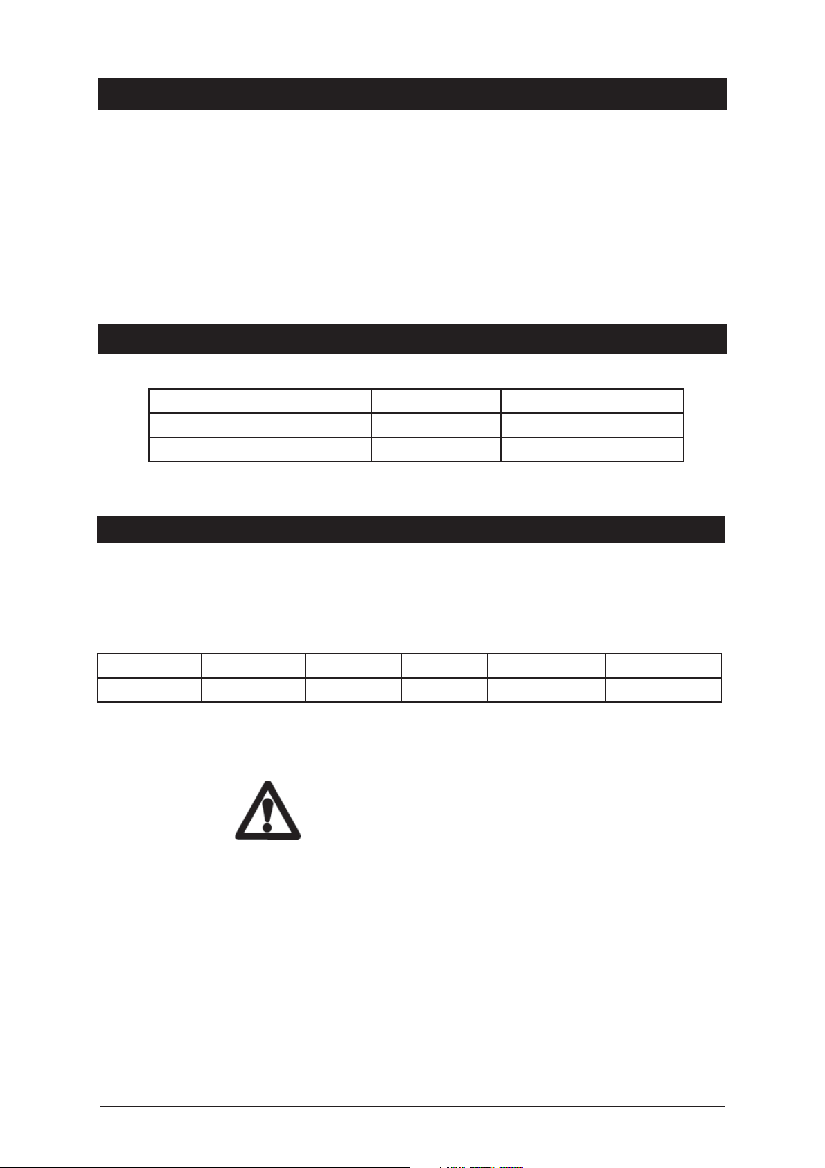
MODEL Capacity Power Rating
MB1BA -Miniboil BA Classic 1.8 Litres 2000 Watts
MB2BA -Miniboil BA Elite 1.8 Litres 2000 Watts
Installation Requirements
Before installing ensure that the following have been provided at the
installation site:
• Sufficient space in the cupboard to install the undersink unit in accordance
with these Installation Instructions. A table of dimensions is given below.
MODEL HEIGHT (mm) DEPTH (mm) Width (mm) Weight Dry (Kg) Weight full (Kg)
Miniboil 338 272 212 6.5 8.3
NOTE: Add 50 mm to the left side of the undersink unit to allow for Air
circulation
• Power supply 220-240 Volt AC, for connection to the heater via a 13 amp
fused spur which must be accessible after installation.
• This switch must provide all-pole disconnection with a contact separation
of at least 3mm, installed in accordance with IEE wiring regulations.
• Cold water supply with a minimum working pressure of 0.7 bar (70 kPa), (1.4
bar (140 kPa) recommended) and a maximum working pressure of 5 bar
(500 kPa) connected via a pressure limiting valve.
A 5 bar (500kPa) pressure limiting valve is supplied with the filter kit and
must be installed.
Important: Do not proceed with the installation if these requirements
are not met.
Zip Hydro Tap Installation and Operating Instructions - 89585UK - June 2011 v1.01 Page 6 of 16
Page 7
Special Tools Required
In addition to normal tools, the following will be required:
• 35mm diameter sheet metal hole punch for sink tops. (not supplied)
• 35mm diameter hole saw for timber bench tops. (not supplied)
• Nut runner tube spanner (supplied) for fixing tap assembly.
When installing a Font unit:
• 108mm diameter sheet metal or hole saw to suit surface being cut.
Installation Procedure
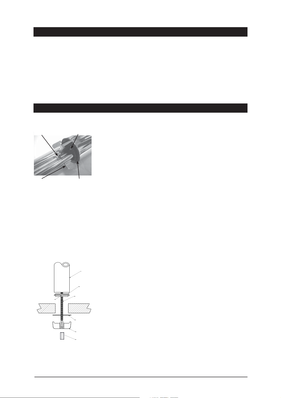
Fixing nut Black spacer
Spider clamp Smear silicon
on underside
flat surface
Note: A stainless steel washer is
supplied to go in between the
Spider Clamp and the underside
of the sink top.
Step A - Installing the tap on a sink
1. Make sure that the tap location will allow the nozzle to drain into the sink.
2. Cut a 35mm hole in the bench / sink top.
3. Install the black plastic spacer to the base of the tap and ensure it remains
in place as this is the moisture seal against the bench / sink top. A light
smearing of silicon sealant on the underside of the spacer will ensure
a watertight fit.
4. Pass the hoses through the 35mm hole and carefully locate the Tap Head
Assembly and black spacer on the bench / sink area.
5. From the underside of the bench / sink area re-locate the S/S washer and
“Spider Clamp” by feeding each of the tubes and electrical cable evenly in
between the legs of the “Spider Clamp”. Slide it up to meet the “All
Thread”, and pass the “All Thread” through the center of the “Spider
Clamp”.
6. Hold the “All Thread” steady and re-fit the 6mm nut to the “All Thread”
using the tube spanner supplied in the kit. Check the Tap Head position
before securing it tightly against the bench / sink top.
See para 3.
Ta p
Black
Plastic
Spacer
All-thread rod
Benchtop
NOTE 1: The tap assembly must not be positioned more than 900mm
above the HydroTap unit.
Failure to do this may result in poor water delivery.
NOTE 2: Under no circumstances should the Tap be twisted after the
installation is complete.
S/S
Washer
Spider
Clamp
Fixing nut
Page 7 of 16 Zip Hydro Tap Installation and Operating Instructions - 89585UK - June 2011 v1.01
Page 8
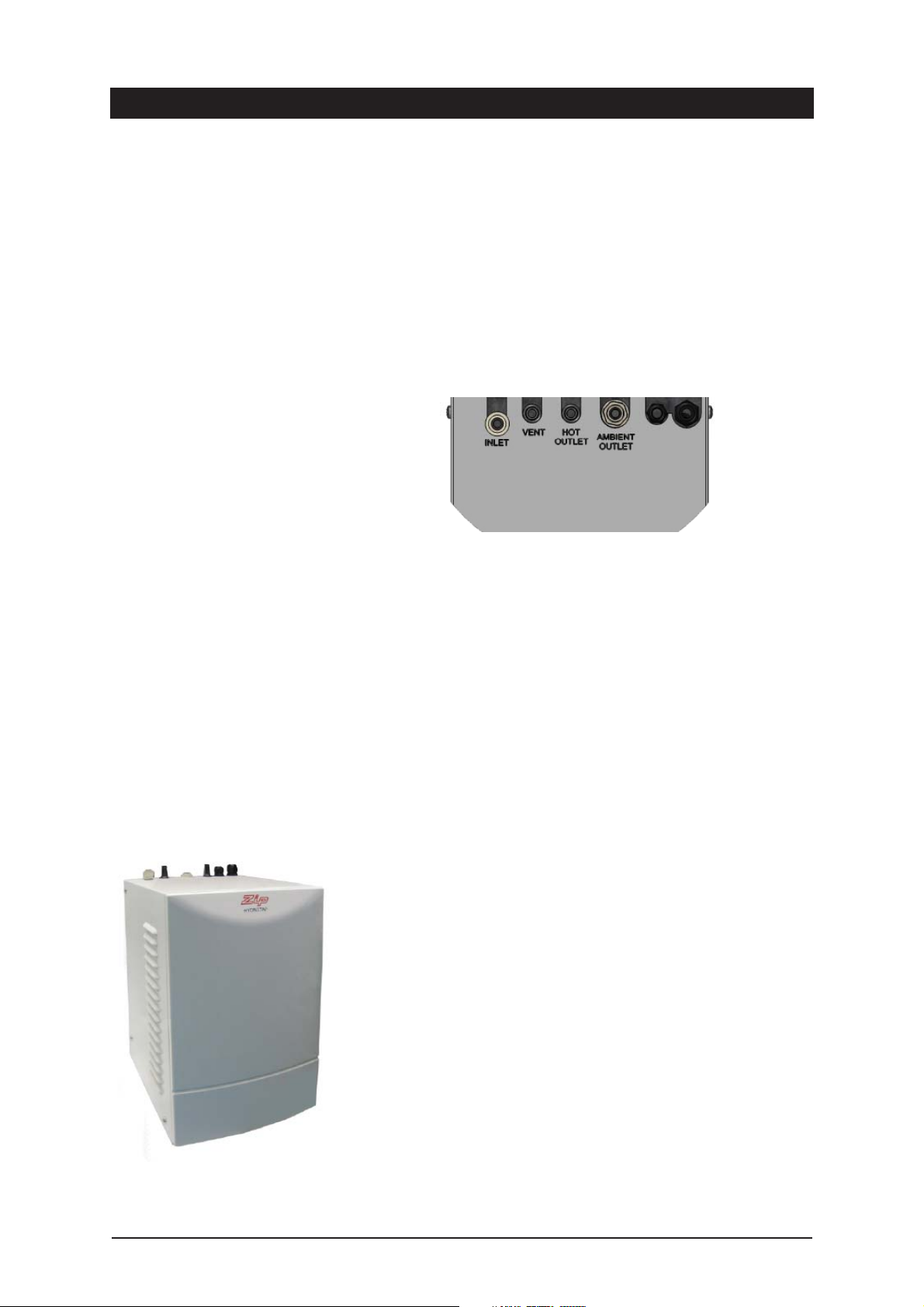
This instruction is critical :
Adjust both cupboard door hinges and
attach the supplied rubber door buffers to
the doors to create a 4 mm air-gap
between the doors and the cupboard. This
is the minimum ventilation requirement
for low usage installations.
Installation Procedure continued
Step B - Installing the undersink unit
SPECIAL NOTE: The HydroTap undersink units are heavy, take note of the
weights listed in the table on page 6. If you think you cannot lift the unit
safely, get help and avoid possible injury.
Position the Zip HydroTap undersink unit as close as possible to directly beneath the
Zip HydroTap tap head.
The connection tubes supplied with the tap head assembly CANNOT be lengthened.
Allow at least a 50 mm air-gap to the LHS for air circulation
Proper air circulation is important for
efficient running of the Hydrotap models.
Therefore cupboard ventilation for
Hydrotap models is recommended.
Connection as viewed from the top
Step C - Installing the filter
The Miniboil is supplied with an external filter (see diagram on next page). It is
important the filter be securely fixed adjacent to the under sink unit in such a
manner as to allow for easy access to the filter, for service and regular
replacement.
The ¼” tube supplied must be carefully measured and cut to allow for the
connection of the filter, double check valve and JG fittings.
Filter assembly sequence: (see fig.1)
- Fit the double check valve to the outlet side of the isolating valve (not supplied).
- Mount the filter in a convenient position using the angle bracket supplied and
connect the filter assembly plumbing between the double check valve and the inlet
of the filter, using the straight ¼” JG fittings supplied. Take note of the flow
direction, marked with an arrow on the top of the filter head.
- Connect the remaining ¼” tube to the outlet of the filter head but do not make the
connection to the undersink unit.
- Before connecting to the undersink unit, it is advisable to flush the filter for
several minutes to remove any fine filter particles or accumulated plumbing
debris. Use a bucket to collect and dispose of, the waste water.
- Once the filter has been flushed, the final connection is made into the undersink
unit using the ¼” JG fitting located on top of the undersink unit.
Filter insertion and replacement: (see fig.2)
Align the tabs of the cartridge with the filter housing and insert it up into the socket.
Turn the cartridge a quarter turn to the right until it locks into position.
Zip Hydro Tap Installation and Operating Instructions - 89585UK - June 2011 v1.01 Page 8 of 16
Page 9
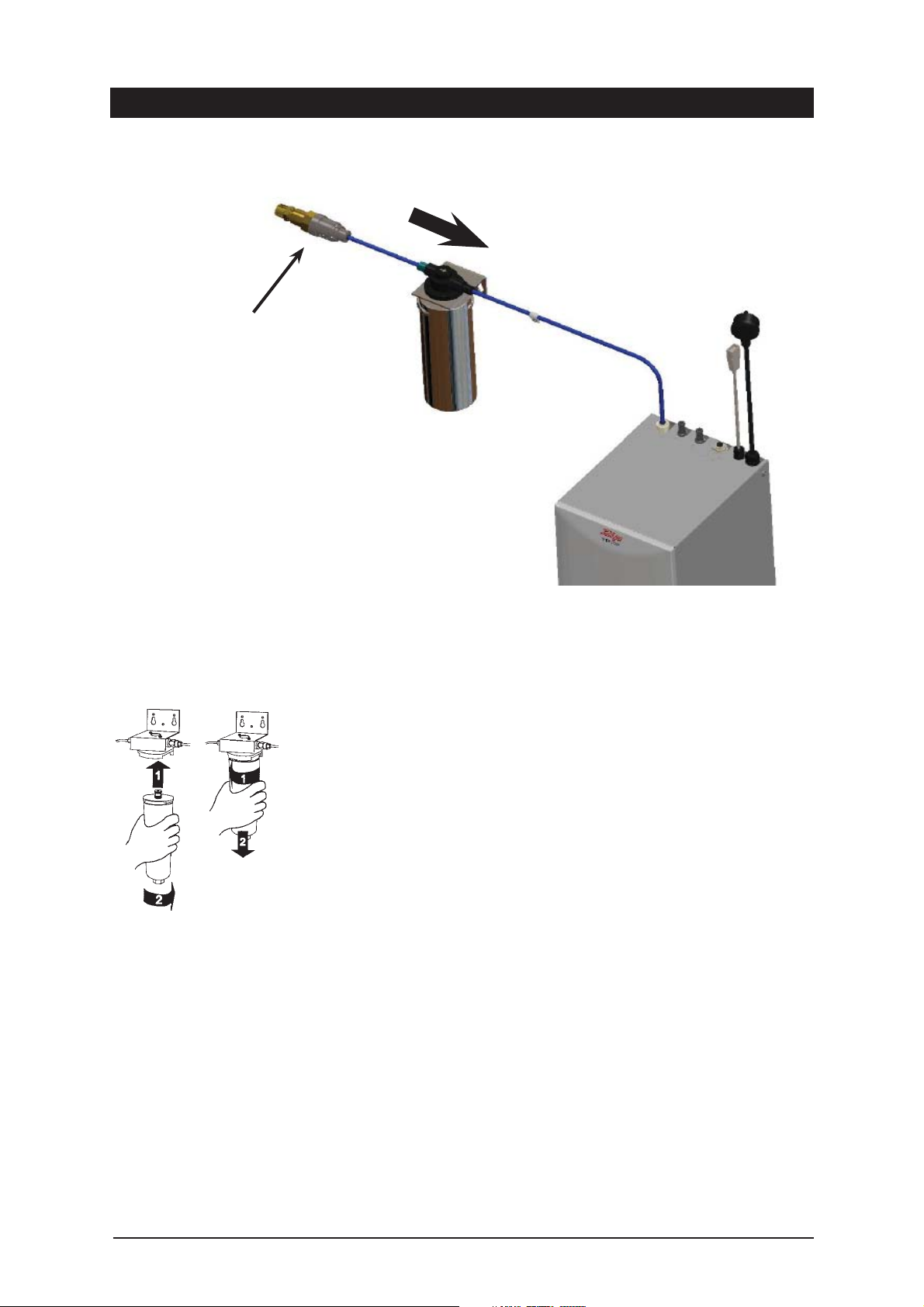
Pressure Limiting Valve
Installation Procedure continued
Reverse this procedure for removal.
Flow Direction
External Filter Connection
fig. 1
Step D - Connecting the tap
Measure and trim the RED tube and connect it to the hot water outlet located
on the top of the undersink unit.
Measure and trim the BLUE tube and connect it to the outlet located on the top
of the undersink unit.
Measure and trim the clear tube and connect it to the vent outlet located on the
top of the undersink unit.
NOTE: All tubes must have a continuous fall back to the undersink unit.
Connect the tap USB connector to the USB lead from on the undersink unit.
Orient the USB plug carefully and connect, do not force the plug. Once
connected, fix the cable to the wall, ensure it is away from any possible water
splashes and is off the floor.
Note: When trimming any silicon tubes trim to minimum length, do not loop
any excess or allow kinking of the tubes. When connecting, slide the tube over
the pipe at least 15mm.
Cartridge replacement
fig. 2
Page 9 of 16 Zip Hydro Tap Installation and Operating Instructions - 89585UK - June 2011 v1.01
Step E - Connecting the water supply
To prevent sediment from entering the Zip HydroTap at connection, flush water
through the supply line thoroughly before connection to the Zip HydroTap.
Connect the water supply to the top of the undersink unit using the JG tube
supplied. Turn on water and check for leaks. If no leaks are evident turn the
power on.
NOTE :
New hose sets supplied with the unit should be used. Do not use old hose
sets.
Page 10
Installation Procedure continued
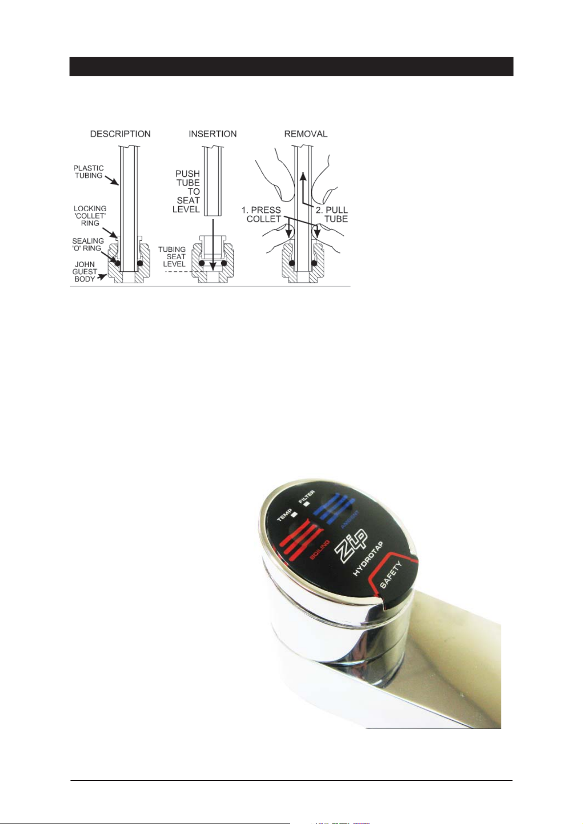
John Guest (JG) fittings - Assembly and Removal
Step F - Testing and commissioning
Boiling
The unit is now running in normal operating mode. The Red LED will flash until usable temperature is reached.
Before using the HydroTap wait 5 minutes after this point to allow adequate fill time. The unit is now ready for use. Test
water delivery from the tap and check for appropriate temperatures. Use cable clips to tidy and secure wiring before
switching power on.
Tap top controls:
The Miniboil uses touch switches to dispense
Boiling and Ambient water. There are no buttons to press and no levers to operate. This
design allows for easier cleaning and operation.
Safety lock:
The safety lock will not allow the dispensing
of Boiling water unless the RED markers for
Boiling water and the safety lock are touched
at the same time.
This function cannot be turned off for your
safety.
Zip Hydro Tap Installation and Operating Instructions - 89585UK - June 2011 v1.01 Page 10 of 16
Page 11
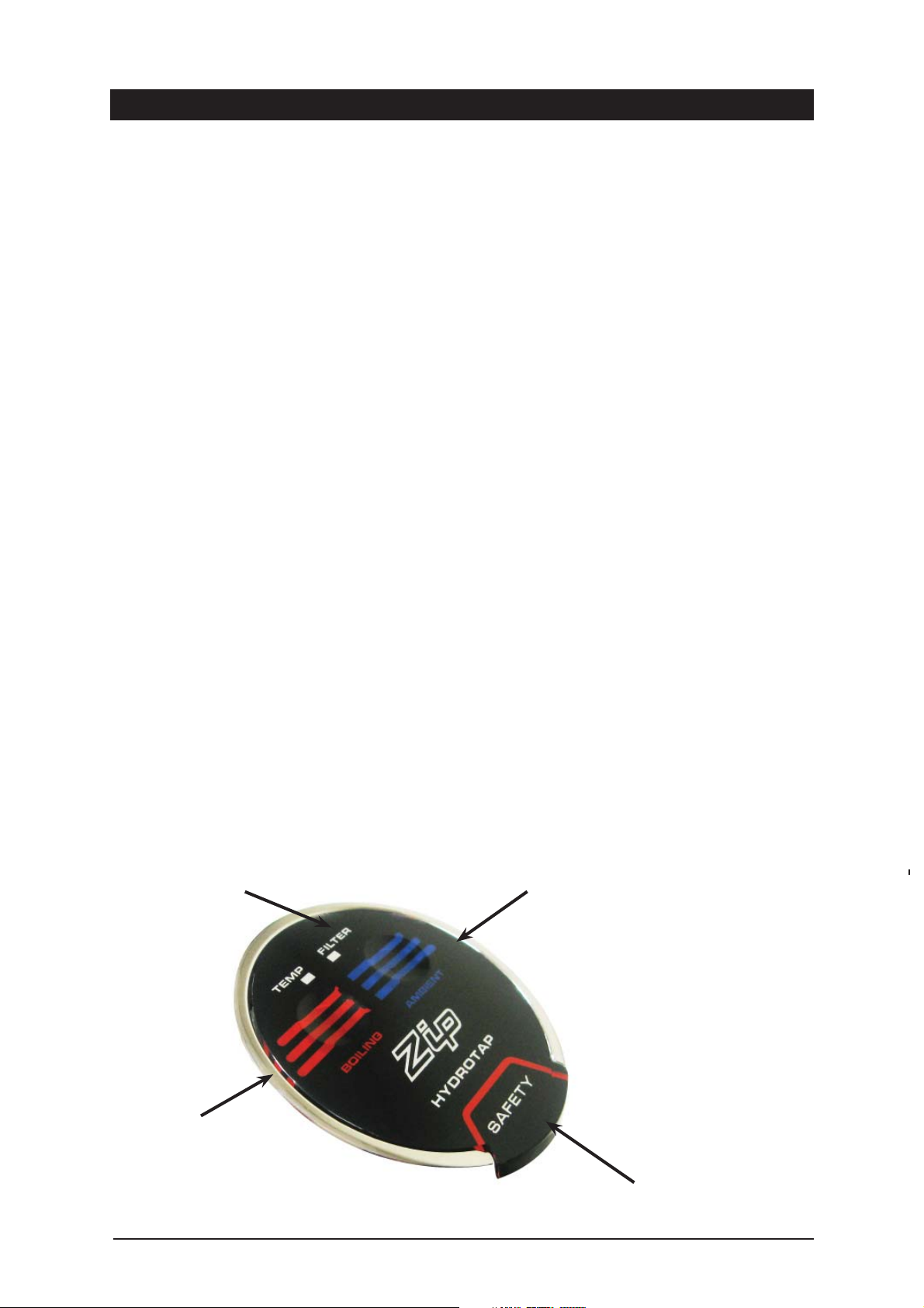
Operating the Tap
• To dispense boiling water touch the Red Markers + Safety Lock simultaneously.
• To dispense ambient water touch the blue markers.
Red Boiling Water Light
ON all the time: This indicates boiling water is ready to be dispensed.
Flashing Fast: This indicates the boiling water is below usable temperature and the Sleep Mode is OFF.
Flashing Slowly: This indicates Sleep Mode is active.
To Reset Sleep Mode
Set Sleep Mode ON: Touch the COLD markers and SAFETY lock simultaneously for at least 5 seconds, until both the
RED and WHITE lights flash together, for a few flashes. Sleep mode maintains the water
temperature at 65ºC and will only become active when the system has not been used for 2
hours. Operation of the tap will wake the system from sleep and boiling water will be available
when the RED light is ON all the time. (This may take a few minutes)
Set Sleep Mode OFF: Touch the COLD markers and SAFETY lock simultaneously for at least 5 seconds, until both the
RED and WHITE lights flash alternately, for a few flashes.
White Filter Light
Flashing: This indicates the filter needs to be replaced. The WHITE light will start to flash when the
counters have recorded 12 months of use or after dispensing 4000 litres, whichever occurs
first.
Set filter light OFF: Reset the system by touching continuously, the COLD and HOT markers. The flashing WHITE
light will turn OFF after 10 seconds and the counters will be set to zero
Filter change: If the filter is changed early, reset the system by touching continuously, the COLD and HOT
markers. The WHITE light will turn ON and after 10 seconds will turn OFF. The counters will be
set to zero. If the filter has reached 4000 litres or 12 months, filter light will be flashing, and
follow the same filter change procedure to reset the filter.
WARNING: When all the lights are flashing, the system has experienced a fault. Turn the power OFF to the
undersink unit for at least 15 minutes. When the power is turned ON the system may revert to
normal operation. If all the lights continue to flash then there is a system fault which must be
rectified by an authorised service agent.
BLUE markers for
Warning lights
Ambient water
RED markers for
Boiling Water
Safety lock
Page 11 of 16 Zip Hydro Tap Installation and Operating Instructions - 89585UK - June 2011 v1.01
Page 12
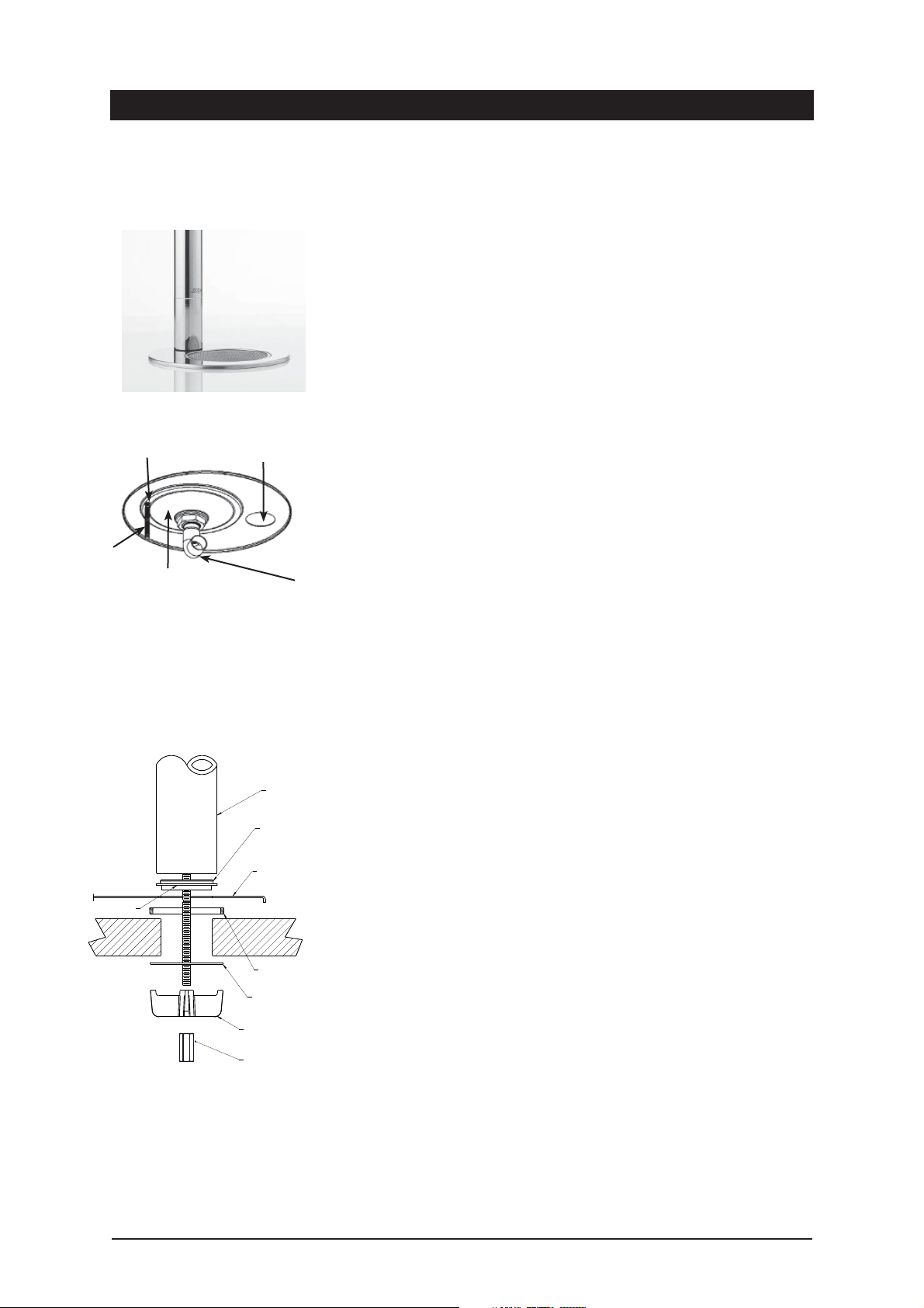
Font Installation Procedure
1. Position the Font template (provided in the kit) on the bench area. Ensure the
position you select is within the length of the supply tube and USB
cable fixed to the Tap Head Assembly. These cannot be extended.
2. Check again for correct positioning. The supply hoses must have constant
fall back to the tank assembly. Cut the holes as shown on the template.
3. Once holes are cut, locate the Font base in position, from the underside,
lightly tighten the fixing stud with the nut and washer provided.
4. Attach the short threaded rod, with the long nut, to the all-thread rod
extending from the tap.
5. Apply a light smear of silicon sealant to the underside of the black base
ring, this will provide a water tight seal against the Font base when
clamped. * Ensure the plastic spacer is correctly located under the Font.
Fixing stud
See para 5.
Cut a 10mm
slot for stud
Hole required for Font
recess 108mm
View from underside
Tap assy
hole 35mm
Drain elbow
Ta p
Black
Plastic
Spacer
Font
Benchtop
6. Now take the Tap Head Assembly. Feed the hoses and USB cable through
the Font base, then through the plastic spacer that sits under the font base
but on the bench top. This stops warping of the base plate. Ensure the Tap
spout is directly centred over the Font drain. Fit the “Spider Clamp”, nut
and washer onto the “All Thread”. Have all the supply tubes and USB cable
located evenly between the “Spider Clamp” legs. When satisfied with the
positioning, tighten the fixing nut with the Tube Spanner provided in the kit.
7. Tighten the fixing stud nut so the Font base is flush with the bench top.
NOTE: The fixing nut above the drain elbow can be loosened to correctly
position the direction of the elbow. Ensure when the re-positioning is
complete the nut is re-tightened to ensure a water tight seal.
8. Connect a drain hose (22mm ID) from the Font base outlet elbow to the
closest drain trap spigot available. If a spigot is not available use the snap
on spigot and worm drive clamps supplied in the kit.
9. Ensure the positioning of the snap-on spigot is on the “sink” side of the
trap and not the “waste” side. Once positioned, a hole (13mm ID) will need
to be drilled to provide waste access to the drain line. The snap-on unit
will require suitable sealant to keep it water tight against the waste pipe.
Finish by fitting the worm drive clamps tightly on either side of the spigot
and fitting worm drive clamps to either end of the drain hose. The drain
hose from the Font must have constant fall
10. Connect the Tap head Assembly supply hoses and vent as per the
instructions contained in the installation procedure section of this
document.
All-thread rod
Note: A stainless steel washer is
supplied to go in between the
Spider Clamp and the underside
of the benchtop. See location as
shown.
Spacer
Under Font
S/S Washer
Spider
Clamp
Fixing nut
*
Warning: If the Zip HydroTap is switched off for a long period of time
(e.g. more than a weekend), run water through the chilled water outlet for
at least 5 minutes before consumption.
Zip Hydro Tap Installation and Operating Instructions - 89585UK - June 2011 v1.01 Page 12 of 16
Page 13

Trouble Shooting
Symptom Possible Cause Solution
No LED display, no tap head
lights or, no water when tap
is operated.
No water flow.
Slow water recovery after
use.
Water not hot.
No power.
Plug is not located in power
socket.
Tap loom is not connected to
HydroTap unit.
Possible internal fault.
Water supply isolated.
Water supply not connected.
Power supply not connected.
Water or moisture on the tap top
control.
Tap top loom is not connected to
HydroTap unit.
Possible internal fault.
Water restriction
Unit is in Sleep Mode.
Unit has just come out of leep
Mode.
Possible internal fault.
Check power supply.
Ensure power plug is correctly fitted and switch is
turned ON.
Check loom connection.
Contact local Zip Service Provider.
Check water supply is on.
Check to ensure plumbing connection is made.
Check power plug is correctly fitted and switch is
turned on.
Ensure tap to control is dry.
Check for loom connection.
Contact local Zip Service Provider.
Check lines for blockages or restrictions
Possible blocked filter
Touch Hot lever and wait for Red LED to stop
flashing.
Wait for Red LED to stop flashing.
Contact local Zip Service Provider.
All the lights are fl ashing Power interruption Turn OFF power for 15 Min and then reconnect.
Water interruption Check for blockages
System Fault Contact local Zip Service Provider
Cleaning
Do not use strong, corrosive, spray or abrasive cleaners. Clean with a soft cloth
or brush and mild soap and water.
Do not spray water over the tap as it may damage the low-voltage electronics.
Undersink units must never be cleaned with water jets.
Page 13 of 16 Zip Hydro Tap Installation and Operating Instructions - 89585UK - June 2011 v1.01
Page 14

Warranty
Certain warranties may be implied by law into your contract with Zip. The warranty provided below is additional to these
implied warranties and nothing set out below shall limit your statutory rights or rights at law.
Zip Heaters (UK) Ltd warrants that, should any part fail within 12 calendar months of installation, that part will be
repaired or replaced free of charge by Zip or its Distributor or Service Provider, except as set out below, provided the
appliance is installed and used strictly in accordance with the instructions supplied, and that failure is not due to
accident, misuse, abuse, unsuitable water conditions, or to any alteration, modification or repair by any party not
expressly nominated by Zip.
No costs are payable by the customer other than any mileage or travelling-time charges incurred by a Zip Service
Provider or the cost of removal, cartage and re-installation of any component of the appliance if it needs to be returned
for repair to Zip or its Distributor.
This warranty does not cover damage resulting from non-operation of the appliance, the use of non authorised parts or
consequential damage to any other goods, furnishings or property.
No warranty applies to the life of any filtration cartridge installed with the appliance as cartridge life may vary according
to water quality and the rate of water consumption.
Zip does not exclude, restrict or modify any liability that cannot be excluded, restricted or modified or which cannot,
except to a limited extent, be excluded, restricted or modified as between the owner or user and Zip under the laws
applicable.
Furthermore, this warranty does not displace any statutory warranty, but, to the extent to which Zip is entitled to do so,
the liability of Zip under any statutory warranty will be limited at Zip’s option to the replacement of the appliance or
supply of equivalent appliance, the payment of the cost of replacing the appliance or acquiring an equivalent appliance,
or the payment of the cost of having the appliance repaired or the repair of the appliance.
Registering Your Purchase
Registering your Zip installation on the Zip website may help to establish date of installation should it become necessary
to service the appliance under terms of the Zip warranty. To register your installation go to www.zipheaters.co.uk and
look under the heading “Warranty”.
As Zip policy is one of continuous product improvement, changes to specifications may be made without prior notice.
Images in this booklet have been modified and may not be true representations of the finished goods.
The standard cup referred to in this publication is 167 ml (6 fl oz).
The standard glass is 200 ml (7 fl oz).
The terms “Zip” and “HydroTap” are registered trade marks of Zip Heaters (Aust) Pty Ltd.
Zip products described in this publication are manufactured under one or more of the following
patents: AU675601, AU637412, AU635979, GB0422305, GB2065848, US4354049, US5103859,
US5099825 and SA2006/08043. Other patents are in force and patent applications are pending.
Zip Hydro Tap Installation and Operating Instructions - 89585UK - June 2011 v1.01 Page 14 of 16
Page 15

Notes
Page 15 of 16 Zip Hydro Tap Installation and Operating Instructions - 89585UK - June 2011 v1.01
Page 16

Head Office
Zip Heaters (UK) Ltd
14 Bertie Ward Way
Dereham
Norfolk NR19 1TE
Zip Hydro Tap Installation and Operating Instructions - 89585UK - June 2011 v1.01 Page 16 of 16
Website: www.zipheaters.co.uk
[email protected]
Telephone: 0845 602 4533
Facsimile: 01362 692 448.
 Loading...