


Contents
Product Description 1
Typical Applications 1
Approvals 1
Warranty 1-2
Warnings 2
Technical Specification 3
Installation:
Location 3-4
Plumbing Connection 4
Electrical Connection 5
Operation 5-6
Saving Energy 6
Routine Preventative Maintenance 6-7
Fault Finding 7-8
Technical Support 8
Spare Parts 9
These instructions should be read carefully
and understood before commencing the
installation. Do not proceed if any part is
unclear or if requirements cannot be fully met.
Please leave these instructions with the end
user after installation.

Product Description
ILH 6 & 9 is a pressure-type, hydraulically controlled instantaneous water
heater for supplying hot water at one or two outlets in close proximity to one
another. (see typical application chart).
ILX6 - 12 is a flow-type electronically controlled instantaneous water heater for
supplying hot water at one or two outlets situated in close proximity to one
another. (See typical application chart).
Typical Applications
ILH6 Wash-hand basin
ILH9 Two wash-hand basins (not simultaneously) or kitchen sink
ILX6 Wash-hand basin
ILX9 Two wash-hand basins (not simultaneously) or kitchen sink or
shower and basin (not simultaneously)
ILX12 Two wash-hand basins or large kitchen sink or shower and basin
Approvals
The ILH6, ILH9, ILX6, ILX9 & ILX12 have been examined, tested, and found,
when correctly fitted, to comply with the requirements of the United Kingdom
Water Regulations/ Byelaws (Scotland). The product, therefore, is listed under
the WRAS (Water Regulations Advisory Scheme) Water Fitting and Materials
Directory - Certificate No. 0209074 (ILH6/9) No.0209073 (ILX6/9/12).
The ILH6, ILH9, ILX6, ILX9 & ILX12 are CE endorsed.
Warranty
Your Zip InLine is precision-built from the finest materials available and should
give many years of trouble-free service. Zip Heater (UK) Ltd warrants that,
should any part of the heater fail within 12 months of installation, that part or
parts will be repaired or replaced by Zip Heaters (UK) Ltd or its accredited
distributor or service engineer, free of charge, except as set out below,
provided that the failure is not due to incorrect use, incorrect installation, dirt in
the inlet or outlet pipes, non-compliance with operating instructions, condition
of water used or unauthorised modification of the heater.
ILH6, ILH9, ILX6, ILX9 & ILX12 Installation Instructions 1

All water heaters are susceptible to lime-scale formation, the degree of which
will depend on local water conditions. Where excessive scale formation is
likely to occur, the use of a scale reduction device is recommended.
The heater should only be returned to Zip or their accredited distributor with the
agreement of Zip Heaters (UK) Ltd, whereupon the only charges payable by the
customer are the cost of removal, re-installation and transport.
This warranty excludes damage resulting from non-operation of the water
heater or consequential damage to any other goods, furnishings or property.
This warranty does not displace any statutory warranty in relation to the heater,
but any liability of Zip Heaters (UK) Ltd under any statutory warranty, other than
in the case of a person ‘dealing as a consumer’ as defined in section 12 of the
Unfair Contract Terms Act 1977, will be limited to a replacement or repair at the
option of Zip Heaters (UK) Ltd.
Warnings
Installation, commissioning and maintenance of this appliance must only
be conducted by a competent installer, who will then be responsible for
adherence to applicable standards and installation regulations.
The ILH6/9 and ILX6/9/12 are for connection to mains supply only. In any
other case please contact Zip Customer Service on 0870 608 8888 for
advice. We cannot be liable for any damages caused by failure to observe
these instructions. When the appliance has been in use for some time.
The fittings may be very hot.
• Do not use the appliance until it has been correctly installed and unless it is
in perfect working order.
• Before commissioning and each time the appliance is emptied, it should be
vented as follows:
1 Disconnect appliance from the mains by removing the fuses.
2 Open and close the hot water tap several times until nore more air
emerges from the tap and all air has been evacuated from the
water heater (approx.1 minute).
3 Reconnect the power supply to the appliance.
• Always switch off the mains electrical supply before removing the front cover.
Never make technical modifications, either to the appliance itself or to electrical
leads and water pipes.
2 ILH6, ILH9, ILX6, ILX9 & ILX12 Installation Instructions

Specification
Product Type ILH6 ILH9 ILX6 ILX9 ILX12
Capacity: 0.2 litre
Pressure type ( rating pressure): 6 bar 10 bar
Heating system: Tubular heater Bare wire
Nominal rating: 6.6 kW/230V 8.8 kW/230V 6.6 kW/230V 8.8 kW/230V 13.5 kW
Rated voltage (50/60) Hz
1/NPE220-240V 1/NPE220-240V 1/NPE220-240V 1/NPE220-240V 3/PE 400V
Rated current 28.7A 38.3A 28.7A 38.3A 19.5A
Max. temperature increase:
At nominal rating & flow rate of 4 l/min 24°C 32°C 24°C 32°C 48°C
flow rate of 6 l/min 16°C 21°C 16°C 21°C 32°C
flow rate of 8 l/min 12°C 16°C 12°C 16°C 24°C
flow rate of 10 l/min 9°C 13°C 9°C 13°C 19°C
Switch-on flow rate: 2.9l/min 3.5l/min 2l / min
Temperature pre-setting: N/A 35 - 55°C
Minimum dynamic water pressure ·8 bar N/A
Suitable for cold water up to: 30°C
Water connection:
1
/
2” B.S.P. for concealed or surface mounting
Required spec. water resistance @15_C: ≥1100Ω cm@15°C (ILX 12 only)
Net weight: 2.2kg
Dimensions (h x w x d): 33cm x 21cm x 9cm
Class / Degree of protection (IEC 529): 1 / IP25
Approvals: See paragraph 2
Installation
This appliance is not intended for use with thermostatic blending valves.
The following must be observed:
• The appliance must be installed in accordance with current IEE regulations.
• Note the specifications on the rating plate and the technical specifications.
• Do not proceed if any stage of installation is unclear.
Installation site
• The installation site must be free from frost at all times.
• The appliance complies with protection type IP25.
• In order to minimise thermal losses, the distance between the heater and the
outlet tap should be as short as possible (<2m).
ILH6, ILH9, ILX6, ILX9 & ILX12 Installation Instructions 3
• Best performance is achieved at a flow pressure of ≥ 3 bar, the rated
pressure of 6 bar (10 bar ILX12) must not be exceeded as failure to
observe this will invalidate the warranty.
• Hot and cold water pipes should be WRAS approved and of copper or
plastic construction.
Installing the appliance
Plumbing
1 An isolating valve must be installed in the cold
water supply line to the heater.
2 Before connecting the water supply to the
appliance flush the pipe by running a quantity of
water into a bucket.
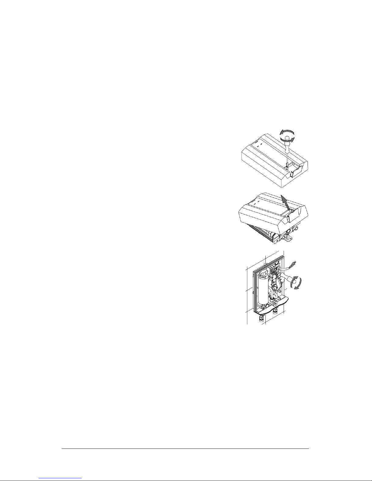
3 Remove the front cover by unscrewing the locking
screw behind the small lid.
4 Locate and break out the required holes and cable
inlets. Use the back-plate as a template to locate
the drilling positions and drill them with a 6mm bit,
ensuring there are no hidden cables or pipe-work.
5 Insert the rubber seal supplied and introduce the
connecting lead. When using a flexible cable it
must be secured, with the cable clamp provided,
on the rear of the appliance back-plate.
6 Screw the appliance into position using the
enclosed rawl plugs and screws.
7 Install the appliance vertically as per diagram. The
inlet and outlet are marked with arrows.
8 The water connections are designed for concealed or surface-mounted
installation and must be carefully sealed with a little PTFE tape when
screwed into the wall connections.
9 The front cover must be cleanly parted at the specified points for surface-
mounted installation or for direct connection to the pipes of the sanitary
fitting using the optional piping kit ZL001.
10 Open the water supply to the appliance and the tap to check all
connections for leaks.
11 Open and close the hot water tap several times until no more air emerges
from the tap and all air has been evacuated from the heater.
4 LH6, ILH9, ILX6, ILX9 & ILX12 Installation Instructions
Electrical connection
The instantaneous water heater must be installed in accordance with
current IEE regulations.
Please ensure that this appliance is earthed.
1 Check that the power supply is switched off prior to the electrical connection!
• The appliance must be permanently connected to the supply through an
isolation switch having a contact separation of at least 3mm in all poles.
• The cross sectional area of the connection cable must be in accordance
with the power rating.
2 The connecting cable should be sealed with the cable
seal and carefully connected to the terminal block using
leads L, N as well as the earth conductor.
• If necessary, the connecting terminal can be moved to
the lower part of the appliance.
• The connecting cable must be adequately secured.
General
1 Locate the front cover and secure with the fixing screw.
2 Completely fill the appliance with water before switching on the power supply.
3 Explain to the user how the instantaneous water heater works and leave
these instructions for their reference.
Operation
Please read these instructions carefully before using the appliance.
ILH6/9
The appliance heats water as it flows through the unit. It only consumes power
during this period. The heating element is switched on automatically when the
minimum pressure is exceeded. The ‘Power’ indicator shows when the heating
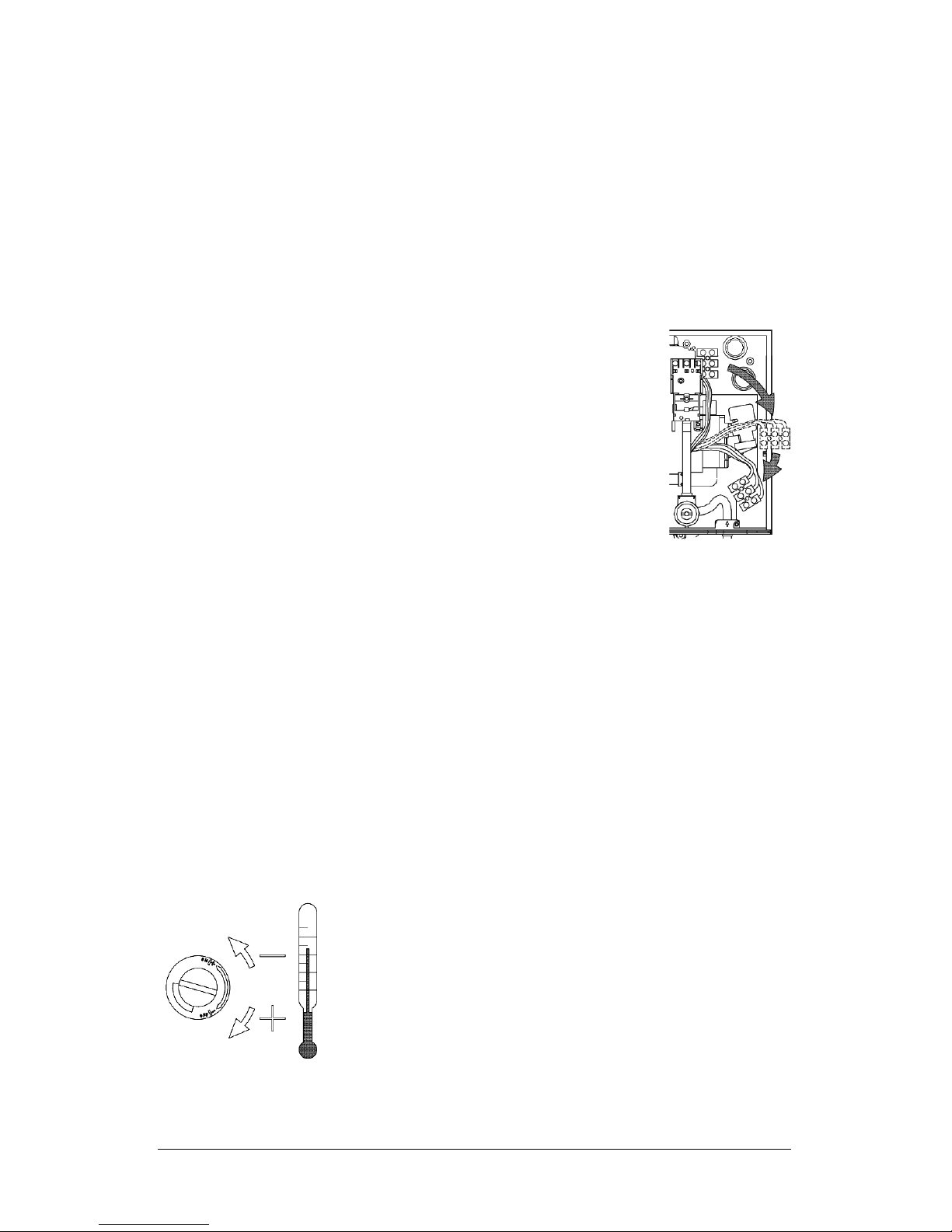
element is switched on. The temperature of the hot water
depends on the rate of flow and the temperature of the
mains water supply. By adjusting the flow rate at the
outlet the delivered water temperature can range from
approx. 40°C to 60°C.
N.B. Reduced flow = Hotter water
Increased flow= Cooler water
The setting for the rate of flow can be changed on the flow valve if, for instance,
the desired hot water temperature is not achieved due to excessively low mains
water temperature.
ILH6, ILH9, ILX6, ILX9 & ILX12 Installation Instructions 5
If the heater supplies two outlets, the water from the unit will be shared between
the outlets. Therefore you should use only one outlet at a time to have sufficient
flow and to avoid variation in temperature.
ILX6/9/12
The appliance heats the water to the required temperature directly as it flows
through the unit. It will switch on automatically when the minimum flow is
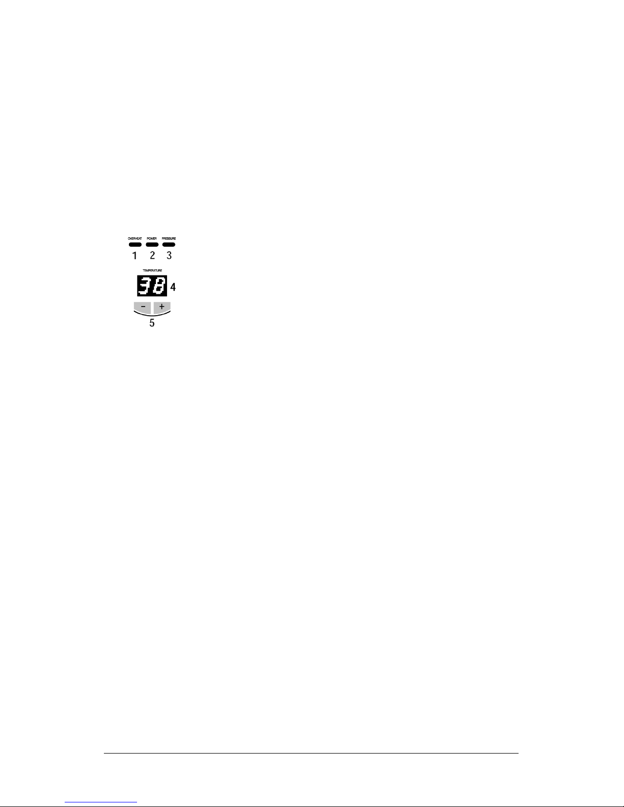
exceeded. The ‘Power’ indicator lights up when the heater is switched on. The
‘Pressure’ indicator lights up when the flow rate is too low.
The power is automatically adjusted by the electronics in line
with the water flow rate, in order to obtain the set temperature
and keep it virtually constant. The required temperature can
be set to within 1°C between 35°C and 55°C using the two
buttons and can be read off the digital display. If the full
power of the unit is insufficient to heat the water to the
required temperature, this is shown by the flashing ‘Power’
indicator. At high incoming water temperatures, the power is
automatically switched off to avoid producing excessively hot water. This is
shown by the ‘Overheat’ indicator.
If the heater provides two outlets, the water from the unit will be shared
between the two outlets. You should, therefore, only use one outlet at a time in
order to obtain sufficient flow.
Saving Energy (ILX 6/9/12)
Set precisely the required temperature on the appliance and only open the hot
water tap. If the water is too hot, set a lower temperature on the appliance
instead of adding cold water. If you add cold water, the heated water is cooled
again and energy is wasted. The cold water added through the tap cannot be
controlled by the electronics and a constant temperature can no longer be
guaranteed.
Routine Preventative Maintenance
N.B. Repairs should only be carried out by competent persons
familiar with instantaneous water heaters.
• Plastic surfaces and fittings may only be wiped with a damp cloth. Never use
abrasive cleaning agents or solvents.
6 LH6, ILH9, ILX6, ILX9 & ILX12 Installation Instructions

• For a good water supply, any aerators and shower-heads should be
separated and cleaned or renewed at regular intervals.
• The electrical and plumbing components should be inspected by a
competent person at least every three years to ensure correct performance
and operational safety at all times.
• The line strainer is located in the flow valve and
should be examined and cleaned periodically, not
only when operation of the appliance deteriorates,
but also in conjunction with regular servicing. Turn
clockwise to remove.
Attention: Residual water will be discharged!
Fault Finding
Problem Possible cause Solution
The “Power” indicator Circuit breaker Have the fault rectified
does not light and the tripped. and reset.
water is cold.
Flow pressure switch is Increase flow pressure
not working (ILH only). (ILH only).
Safety thermal cut-out Contact customer service
tripped (ILH only). (ILH only). Re-set.
The “Power” indicator Heating element is faulty. Replace the element,
lights, but the water contact customer service.
is cold.
Electronics faulty (ILX only). Reset fuse. In case of
repeated failures, contact
customer service
(ILX only).
Safety thermal cut-out Reset. In case of repeated
tripped. (ILX only). trips contact customer
service. (ILX only).
The “Overheat” Over-temperature (ILH only). Increase flow, check cold
indicator lights. water temperature
(ILH only).
Dirt in tap or filter (ILH only). Clean as necessary (ILH only).
ILH6, ILH9, ILX6, ILX9 & ILX12 Installation Instructions 7

Fault Finding (cont.)
Problem Possible cause Solution
The “Pressure” indicator Flow rate too low (ILX only). Increase flow pressure
lights, water remains cold. (ILX only).
Water flow rate is less Depends on the heater. Check technical
than expected. specifications.
Minimum dynamic water.
pressure is below ·8 bar
Outlet fitting dirty or calcified. Clean tap fitting or
shower head.
Filter dirty or calcified. Clean or renew the filter.
Unsuitable tap. Contact customer service.
The hot water is not Electronics faulty (ILX only). Reset fuse. In case of
hot enough. repeated failures, contact
customer service (ILX only).
Flow rate is too high (winter?). Reduce the water flow slightly.
Heating element defect. Contact customer service.
Flow and temperature of The water pressure or the Stabilise flow pressure, check
the hot water varies. voltage is varying (ILH only). supply voltage (ILH only).
Temperature and Cold water is being Only hot water can be
pressure vary. added (ILX only). delivered to within one
degree (ILX only).
Technical Support
If a fault in your appliance cannot be rectified with the aid of this table, please
contact Zip Heaters who will either assist you directly or put you in touch with
a service engineer in your area. Always specify the appliance model and serial
numbers. Use this chart to record the number during installation.
*Model No. *Serial No. Date of Installation
Zip Heaters (UK) Ltd
Tel: 0870 608 8888 Fax: 01362 692448
e-mail: service@zipheaters.co.uk
8 LH6, ILH9, ILX6, ILX9 & ILX12 Installation Instructions

Spare Parts
ILH Layout of appliance and spare parts
When ordering, please always specify the appliance model and serial number!
Item Description
1
1
/
2
”
b.s.p. connector
2 Temperature monitor
3 3 Flow valve with filter
4 Heating element
5 Safety thermal cut-out
6 Appliance front cover
7 Connection terminal
8 Differential pressure switch
9 Flow reducer
11 Cable seal
12 Pilot lamps
13 Set of small spare parts (Washers,
filter, screws and micro-switch)
14 Cold water inlet
ILX
Item Description
1
1
/
2
”
b.s.p. connector
2 Flow rate adjustment
with filter
3 Heating element
4 Display panel
5 Safety thermal
cut-out (STB)
6 Appliance front cover
7 Connection terminal
8 Electronic board
9 Flow sensor
10 Cold water inlet
11 Cable seal
12 Set of small spare
parts (Washers, filter,
screws and micro-switch)
ILH6, ILH9, ILX6, ILX9 & ILX12 Installation Instructions 9
 Loading...