

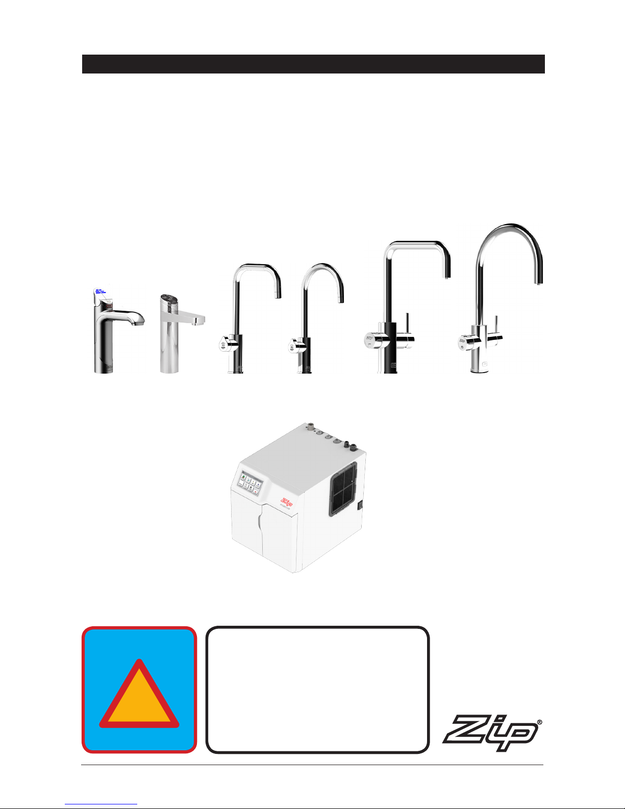
Zip Heaters HydroTap G4 Command-Centre, HydroTap G4 Classic, HydroTap G4 Arc, HydroTap G4 Elite, HydroTap G4 Cube Installation Instructions
Page 1
804052UK - Residential chilled and sparkling installation instructions - Sept 2016 - v3.02 Page 1 of 20
Zip HydroTap G4
Installation instructions
®
Chilled sparkling model
Command-CentreTM.
Filtered chilled and sparkling drinking water for residential kitchens.
Affix model number label
here
804052UK
VENTILATION IS
ESSENTIAL
SECTION 2 'VENTILATION'
READ BEFORE YOU START
!
READ
Page 2
Page 2 of 20 804052UK - Residential chilled and sparkling installation instructions - Sept 2016 - v3.02
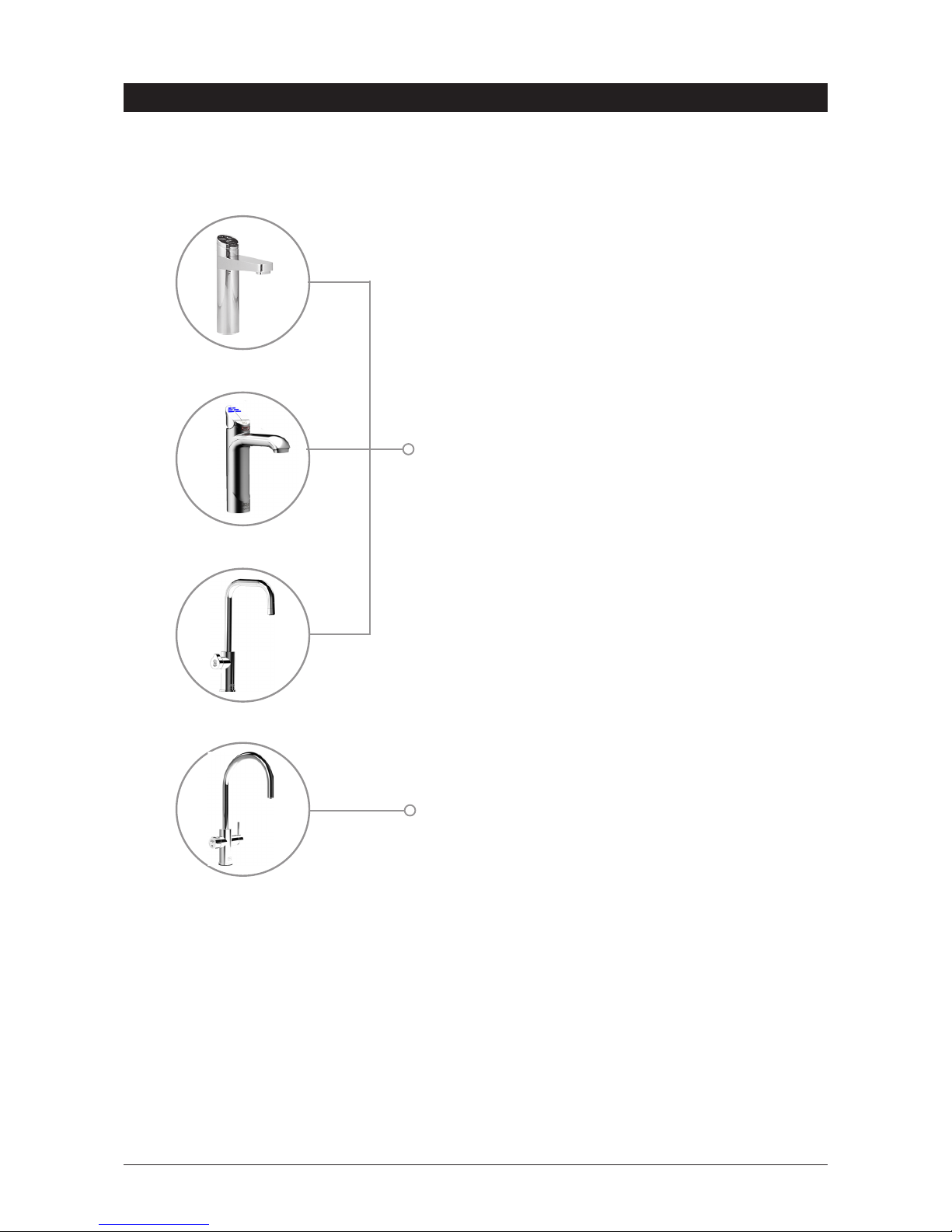
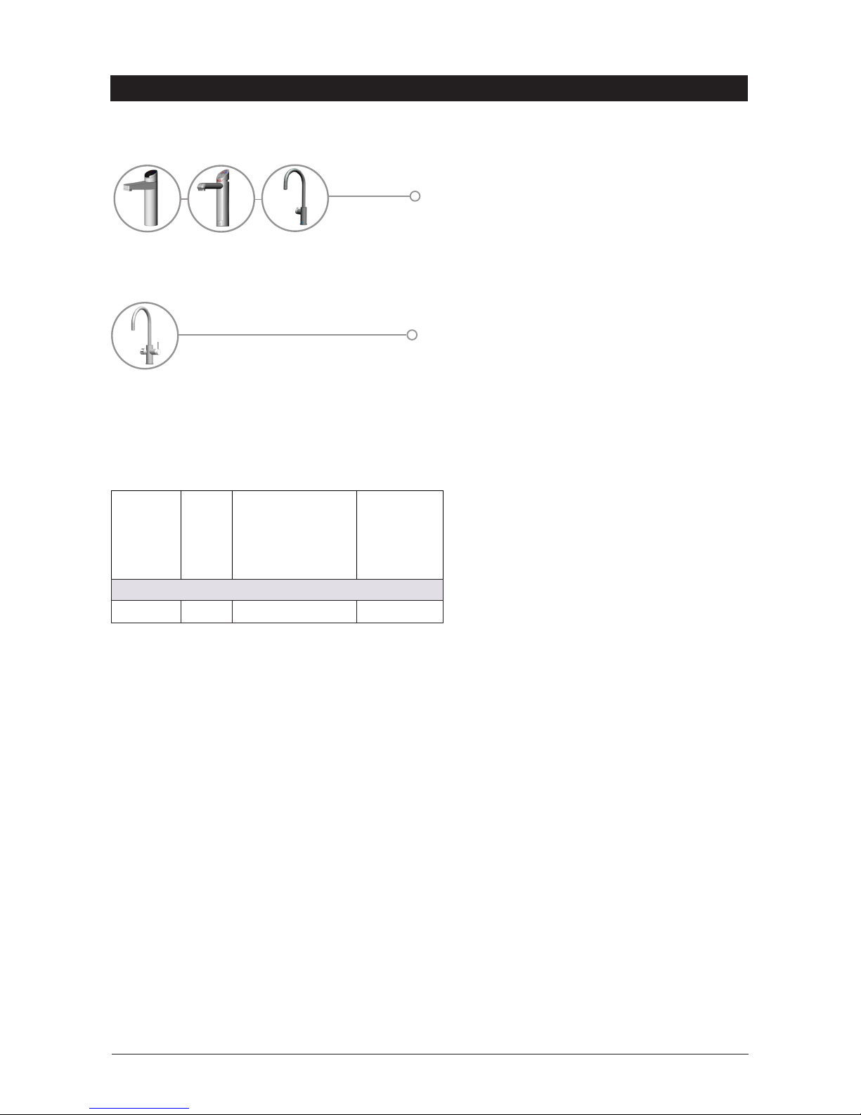
Tap options
The G4 series offers a range of interchangeable taps to suit the customer's needs.
Classic HydroTap®G4 range
Arc / Cube HydroTap®G4 range
Elite HydroTap®G4 range
These standalone taps are directly compatible with
the G4 Command-CentreTM.
Celsius HydroTap®G4 range
The Celsius range offer instant chilled and sparkling
water together with the an integral mixer to provide
mixed hot and cold water from the mains.
Page 3

804052UK - Residential chilled and sparkling installation instructions - Sept 2016 - v3.02 Page 3 of 20
HydroTap®G4 specifications
Installation check list .................................................................................................................... 4
General product features ............................................................................................................. 5
Important safety instructions ........................................................................................................ 6
Warnings ...................................................................................................................................... 7
Major components and accessories ............................................................................................. 8
Technical specification ................................................................................................................. 9
Before installation and site requirements ..................................................................................... 10
Installation instructions
Step 1 -
Measure and cut all the tap holes before fitting the taps. Refer to 803341UK Tap installation
instructions supplied with the tap head.
Step 2 - Check for adequate ventilation.
Section 1 - Ventilation.
1.1 - Ventilation on all models ........................................................................................... 11
Step 3 -
Fit the CO2 gas cylinder
Section 2 - CO2 cylinder and regulator
2.1 - 2.4 Connect, secure and test the CO2 cylinder ......................................................... 12-13
Step 4
- Install the Command-CentreTM.
Section 3 - Command-CentreTM installation
3.1- Mains water (braided) supply hose ........................................................................... 13
3.2- Chilled and sparkling HydroTap®G4 models.............................................................. 14
3.3- Chilled and sparkling HydroTap®G4 models together with mixed hot cold water ...... 15
Step 5
Commission the HydroTap®G4
Section 4 - Commissioning
4.1- 4.2 Select language and CO2 purge .......................................................................... 16
4.3- Filter flush .................................................................................................................. 17
Trouble shooting
Trouble shooting table .................................................................................................................. 18
End of life disposal ....................................................................................................................... 18
Warranty ....................................................................................................................................... 19
Contact details ............................................................................................................................. 20
Index
Page 4

Page 4 of 20 804052UK - Residential chilled and sparkling installation instructions - Sept 2016 - v3.02
Before installation
• Read the instructions and check if there is adequate space to mount all of the components.
• Note Not all fittings are supplied with the appliance kit. Isolation valves are not supplied.
• Check the mains water pressure is within min / max requirements (see page 9).
• Check the water quality to determine if extra filtration will be required.
• Note This product must be fitted to a potable water supply.
• Check the appliance rating plate and ensure correct power is available for the appliance.
• Check the under counter cupboard floor has sufficient strength to support the Command-CentreTM
when full of water (see page 9 for weights).
Before commissioning
• Check the Command-CentreTM has been installed correctly.
• Check all plumbing fittings have been tightened.
• Ensure the outlet and vent pipes are positioned to drain correctly into a sink or font.
• Ensure there is adequate ventilation.
• Check all tubes and pipes from the Command-CentreTM to the tap have a constant rise and there
are no sags or kinks in the hoses.
• Check all electrical connections are correct and there are no loose wires.
Commission (see section 4)
• Flush the supply line before connecting.
• Turn on the gas and water and check for leaks.
• Purge the CO2.
• Flush the filters.
• Where applicable, programme the Command-CentreTM to suit the customer’s requirements.
Installation checklist
Page 5
804052UK - Residential chilled and sparkling installation instructions - Sept 2016 - v3.02 Page 5 of 20
General product features
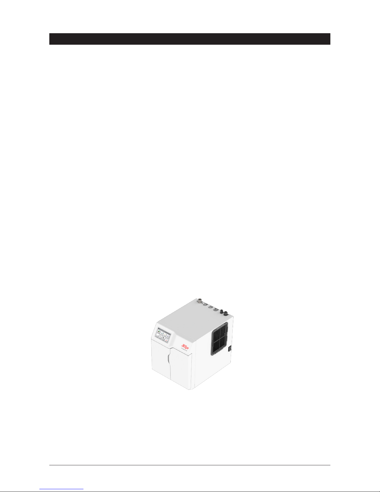
HydroTap®G4 Command-Centre
TM
Chilled and sparkling
Thank you for purchasing a Zip HydroTap®G4. Please read and follow these instructions carefully to ensure
safe and trouble free operation. If help and advice is required, please call 0345 6 005 005.
What is the Zip HydroTap®G4?
This Zip HydroTap®G4 is an electronically controlled, filtered, chilled and sparkling water, drinking system for
the kitchen. The Zip HydroTap®G4 Command-CentreTM is an under counter drinking water appliance with a
dispensing tap mounted on a sink or worktop, which has been designed for residential applications. The Zip
HydroTap®G4 Command-CentreTM utilises a conventional refrigerant compressor to chill the water and uses a
CO2 gas cylinder to carbonate the chilled water. The Command-CentreTM will dispense chilled and sparkling
water (factory set to 3-5°C). The HydroTap®G4 is NOT designed to be used for sanitary fixtures.
There are various energy saving options accessible via the main menu.
The water filter and CO2 cylinder are disposable items which will require periodic replacement and are
covered by a limited OEM (original equipment manufacturer) warranty.
It is important that the installation be undertaken safely, correctly and completely, in order to utilise all the
benefits that the HydroTap®G4 can provide. Each system can be ordered with the tap head assembly for
disabled use. The disabled levers are supplied with Braille caps for the visually impaired.
Page 6

Page 6 of 20 804052UK - Residential chilled and sparkling installation instructions - Sept 2016 - v3.02
Important safety instructions
This manual contains important safety and installation instructions for the Zip HydroTap®G4.
Please read all warnings, installation requirements and installation instructions before installing any Zip
HydroTap®G4. This system must be installed in accordance with water supply byelaws,
current IEE regulations and relevant local authority byelaws.
Safety
This appliance is not intended for use by children under 8 years or persons (including
children under 8 years) with reduced physical, sensory or mental capabilities, or lack of
experience and knowledge, unless they have been given supervision or instruction concerning the use of the
appliance by a person responsible for their safety. Children should be supervised to ensure that they do not
play with the appliance. Cleaning and user maintenance shall not be made by children without supervision.
Refrigerant
The Zip HydroTap®G4 Command-CentreTM contains R134A refrigerant under pressure. Maintenance of the
refrigeration unit must be carried out by an accredited service provider or qualified refrigeration technician.
Qualifications
If the power cable is damaged it must be repaired only by a qualified technician. To avoid hazards, all
installation procedures must be carried out by a suitably qualified tradesperson. The power cable and power
outlet must be in a safe visible position for connection.
Lifting
Take care when lifting the Zip HydroTap®G4. The Command-CentreTM may exceed safe lifting limits. If
you feel this is beyond your personal capabilities, please seek assistance with the lift. The weight of the
Command-CentreTM is marked on the packaging. Do not lift the Command-CentreTM by the front cover or any
of its connections. Refer to the technical specification, see page 9, for the weight of the product.
Airflow
The Zip HydroTap®G4 operates within the ambient temperature range 5ºC - 35ºC. Proper air circulation
must be provided. The system will operate satisfactorily only if the recommended air gaps are provided. See
Section 1 'Ventilation', page 11, for correct installation to prevent overheating.
Frost protection
If the HydroTap®G4 is located where the ambient air temperature could fall below 5ºC when the heater is
not in use, do not turn off the appliance electrically. This safeguard does not offer the same protection to the
connecting pipework and fittings.o
Positioning
It is important to ensure the Command-CentreTM is positioned in an accessible area close to the floor level.
The Command-Centre
TM
must have it’s base mounted in a horizontal position with all inlets and outlets facing
up. The tap must be located above the Command-CentreTM. See Section 3, Command-CentreTM installation.
Page 7
804052UK - Residential chilled and sparkling installation instructions - Sept 2016 - v3.02 Page 7 of 20
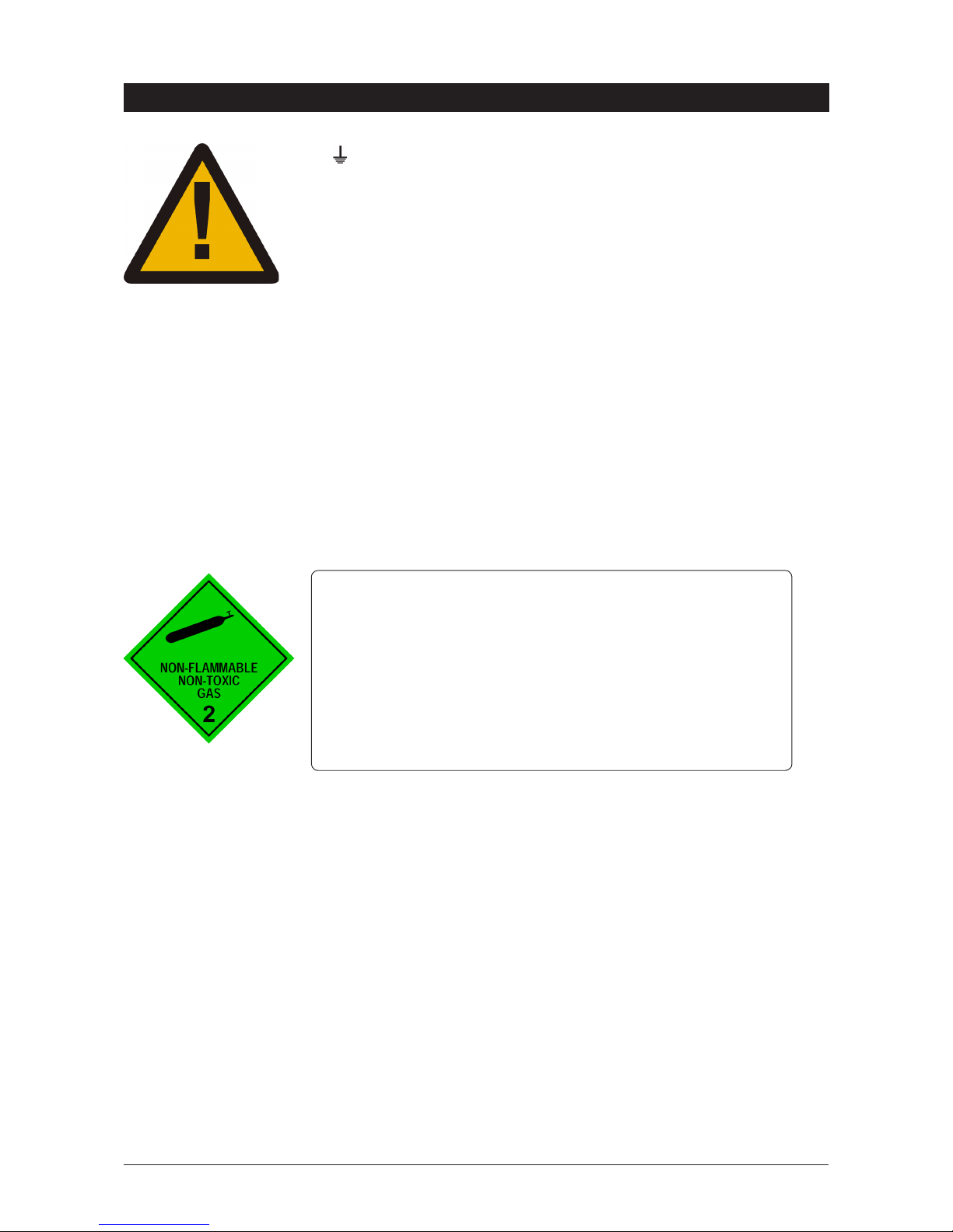
CO2 - Disposable cylinder
Compressed carbon dioxide, food grade
Cylinder specifications
•UNNo.1013 •Class2.2
•CodeZT400 •Volume2.2litres
•Contents1kg •Tare1.745kg
•Testpressure12MPa(120bar) •Boilingpoint-78.5°C
•Nonflammablegas •Nontoxicgas
•Std:EN12205 •Temprange-20°Cto+65°C
Important safety instructions
WARNINGS
• The Zip HydroTap®G4 Command-CentreTM must be earthed. The
resistance of the earth connection from each exposed metal part must be
less than 1Ω.
• All installation and service work must be completed by trained and suitably
qualified tradespeople. Faulty operation due to unqualified persons working
on this product, or any other Zip product may void warranty coverage.
• As the installer, it is your responsibility to supply (if necessary) and install all
valves as required by local regulations and relevant standards.
• This Zip HydroTap®G4 Command-CentreTM is rated for 230V 50Hz AC
operation.
• Do not remove the cover of the appliance under any circumstances without
first isolating the appliance from the power supply.
• The Zip HydroTap®G4 Command-Centre
TM
must never be located near, or
cleaned with water jets.
• Do not expose the Zip HydroTap
®
G4 to the elements of nature.
• Due to the process of continuous improvement, Zip reserves the right to
change details mentioned in this manual, without notice.
CO2 Cylinder warnings
•
Pressurised container.
•
Protect from sunlight.
•
Contains gas under pressure, may explode if heated.
•
Donotexposetotemperaturesexceeding50˚C.
•
Do not pierce or burn, even after use.
•
Do not refill – non rechargeable.
•
Ensure cylinder is empty before disposal.
•
Do not expose to naked flame or any incandescent material.
•
Keep out of reach of children.
•
High concentration of gas may cause asphyxiation.
•
Use only in ventilated areas.
•
Store in an area no less than 38 cubic meters.
•
Use only in an upright position.
•
This bottle must be used with the approved pressure regulator.
•
Avoid shock.
•
Use according to MSDS. (Material safety data sheet).
Visit www.zipwater.com/uk to ensure you have the latest copy.
Page 8
Page 8 of 20 804052UK - Residential chilled and sparkling installation instructions - Sept 2016 - v3.02
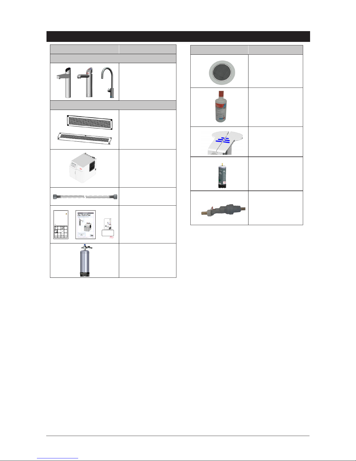
Major components and accessories
Accessories Description
Font kit
Classic & Elite
or
Arc / Cube
Replacement
internal 0.2 micron
filter
Disabled lever kit
(Classic HydroTap®)
1 X
CO2 gas cylinder
Recommended
water block
Parts supplied Description
Tap options
1 x HydroTap®G4
Classic
Elite or # Arc / Cube
#
(inc. Tube kit)
Command-CentreTM and components
Vent kit
2 x outlet vent
1 x inlet vent
1 x
Command-CentreTM
with air and water
filters
1 x Mains water
connection hose
1 x User guide and
1 x Quick start
guide
1 x Installation
instruction
1 x
CO2 gas cylinder
assembly
801599 - HydroTap User Guide - Nov 2013 UK - V1.05 Page 1 of 20
ZIP HydroTap
User Guide
®
•
Tap Operation...................(Pages 2-5)
•
LCD Screen & Menu .......(Pages 6-18)
•
Maintenance.................... (Pages 18-20)
•
Date of Installation.........
Affix Model Number Label
Here
801599
BC160/125G4
BC240/175G4
BCH160/125G4
BCH240/175G4
AV160/125G4
AN160/125G4
AV240/175G4
AN240/175G4
801600 - Zip Quick Start Guide - October 2013 - V1.06
Parts Supplied Description Parts Supplied Description
1 off
Hydrotap Tap
and hoses
Duct kit
1x Air Duct
1 x Mounting
plate
1 off
Undersink Unit
with air and water-
filter
Vent kit
1 x Kickboard
louvre
1 x Door vent
louvre
1 x front vent grill
1 x Restrictaflow
valve and Tee
piece for Mixer
Taps
1 off
HydroTap
Booster heater
and hoses
(Supplied with
240/175 models)
1 off Mains water
connection hose
QUICK START GUIDE
Note: This quick start guide must be read in conjunction with
the main installation and user instructions
• Before proceeding, read the installation and user instructions
• Check all the components are present and correct.
• Check that you have all the necessary tools
•
Ensure the underbench can support the product weight when full of water,
(Check the specifications in the main book and allow an extra 5-8kg when full. )
Before installing ensure the following have been provided at
the installation site:
• Sufficient space in the cupboard to install all of the undersink units in accordance
with these Installation Instructions. Refer to technical specification for dimensions. If
required, make allowance for a booster heater. (Refer to the main book, for detailed
installation instructions).
• A potable water supply connection with isolating valve inside the cupboard within
reach of the flexible braided hose and positioned so that the connection point and the
stop cock will not be obstructed when all the undersink units are installed.
• For Zip HydroTap 160/125 &160/175 models, a 220-240Vac, 10A GPO will be
required. For Zip HydroTap 240/175 models, two 220-240Vac, 10A GPOs will be
required. (One GPO is for the Zip HydroTap and the other for the Booster heater).
NOTE: Check the cable lengths and outlet positions before proceeding.
• A potable cold water supply with a minimum working pressure of 172kPa and a
maximum working pressure of 700kPa connected via an isolation valve.
• For the mains pressure All-IN-ONE, both a hot and cold water supply will be required.
• The undersink appliances must be mounted in upright positions as shown in the
diagrams.
IMPORTANT!
Do not proceed with the installation if these
requirements are not met.
STEP 1-
Prepare and fit the Taps
Hole positioning: Position the tap such that it dispenses into
the sink bowl with ample clearance for a cup or tea pot. Alternatively,
the tap could be mounted away from the sink using a Zip Font, avail-
able as an accessory.
Apply a light smearing of silicon sealant
on the underside of the upper spacer to
ensure a watertight fi t.
For HydroTap and Mixer taps
cut a 35mm hole in the bench / sink top.
BENCH TOP
Ø35mm
HydroTap Tap
Mixer Tap
4-in-1
(If required)
NUT
LOWER RUBBER
WASHER
UPPER
RUBBER
WASHER
WASHER
BRAIDED
HOSE x 3
UPPER RUB-
BER WASHER
LOWER RUB-
BER WASHER
WASHER
NUT
White Hose
Ext. Mains
Blue band
Mixer IN
Red band
Mixer Out
O-RING
BASE
BLOCK
SPIDER
BASE
BLOCK
NUT
USB
CABLE
ALL
THREAD
ROD
NOTE: feed each of
the tubes and elec-
trical cable evenly in
between the legs of
the BASE BLOCK
SPIDER.
All-In-One Tap
(If required)
For AIO mains and vented Taps
Cut a 50mm hole in the bench / sink top.
NOTE: make sure the tap location will allow the nozzle to drain into the sink.
SINK TOP
50mm
ALL THREAD
ROD
STAINLESS
STEEL
WASHER
SPIDER
CLAMP
NUT
BLACK
PLASTIC
SPACER
NOTE: feed each of the three tubes and
electrical cable evenly in between the legs of
the SPIDER CLAMP when installing.
Fit the
STAINLESS STEEL
WASHER,
SPIDER CLAMP,
AND 6mm NUT.
6mm
NUT
SPIDER
CLAMP
Stainless
washer
Black plastic
spacer
35mm dia hole
Sink
O-RING
SINK TOP
Fit the O-ring to the underside of the AIO tap
then pass all hoses through the 50mm hole.
Chiller
connection
BLUE
From Mixer OUT to Tap - Vented version only
Boiler
connection
RED
Blue ring on
RHS mains IN to
Mixer IN
White ring
on LHS to
Mains in
Tap
O ring Base
Clear tube to Vent
ForAccessoriescontactZip:
Tel 0345 6 005 005
Website:www.zipwater.com/uk
Email:[email protected]
Page 9
804052UK - Residential chilled and sparkling installation instructions - Sept 2016 - v3.02 Page 9 of 20
Technical specifications
* Add an extra 5 kg when full of water
13A
sockets
required
Power
rating
(kW)
230V
Unit Dimensions
W x D x H (mm)
with air duct
*Dry weight
(kg)
Chilled and sparkling models
1x13A 0.35
280 x 405 x 333
30kg
Min / Max water supply pressure
HydroTaps and Mains All-in-One taps..............................0.25 MPa (2.5 bar) - 0.7 MPa (7 bar)
Chilled and sparkling HydroTap®G4 range
Chilled, sparkling and filtered.
Arc / Cube
Elite
Classic
HydroTap®s
Note
Chilled water will continue to be dispensed after the rated capacity has been used, although this may
affect the dispense temperature.
HydroTap®s with mixer taps
Chilled, sparkling, filtered and mixed hot & cold.
Celsius
Page 10
Page 10 of 20 804052UK - Residential chilled and sparkling installation instructions - Sept 2016 - v3.02
Before installation
Before installation ensure that the following have been
provided at the installation site
•
Review of all the technical specifications.
•
Ensure the under counter cupboard floor can support the product weight
when full of water (allow an extra 5kg when full).
•
Sufficient space in the cupboard to install the Command-CentreTM and
other components in accordance with these installation instructions. See
technical specification, page 9 for dimensions. See sections 3 to 4, pages
12 to 14 for installation instructions.
•
For Zip HydroTap®G4 Chilled and sparkling only models, 1 x 220-240V AC
13A socket will be required.
•
The Command-CentreTM must be installed in accordance with IEE
regulations. See Technical specification, page 9 for power ratings.
Note Check all cable and hose lengths against inlet /outlet positions before
proceeding (see sections 3 to 4, pages 12 to 15 for general layout).
•
A potable water supply connection with isolating valve inside the
cupboard within reach of the braided hoses and positioned so that the
connection point and the stop cock will not be obstructed when the
Command-CentreTM is installed.
•
Apotablecoldwatersupplywithaminimumworkingpressureof:
(see page 9 min. / max. water supply pressure).
•
If pressure is likely to exceed 0.7 MPa (7 bar), install a 0.35 MPa (3.5
bar) pressure limiting valve.
•
The appliance must be placed with its base in a horizontal position.
IMPORTANT!
Do not proceed with the installation if these requirements are
not met.
Page 11
804052UK - Residential chilled and sparkling installation instructions - Sept 2016 - v3.02 Page 11 of 20
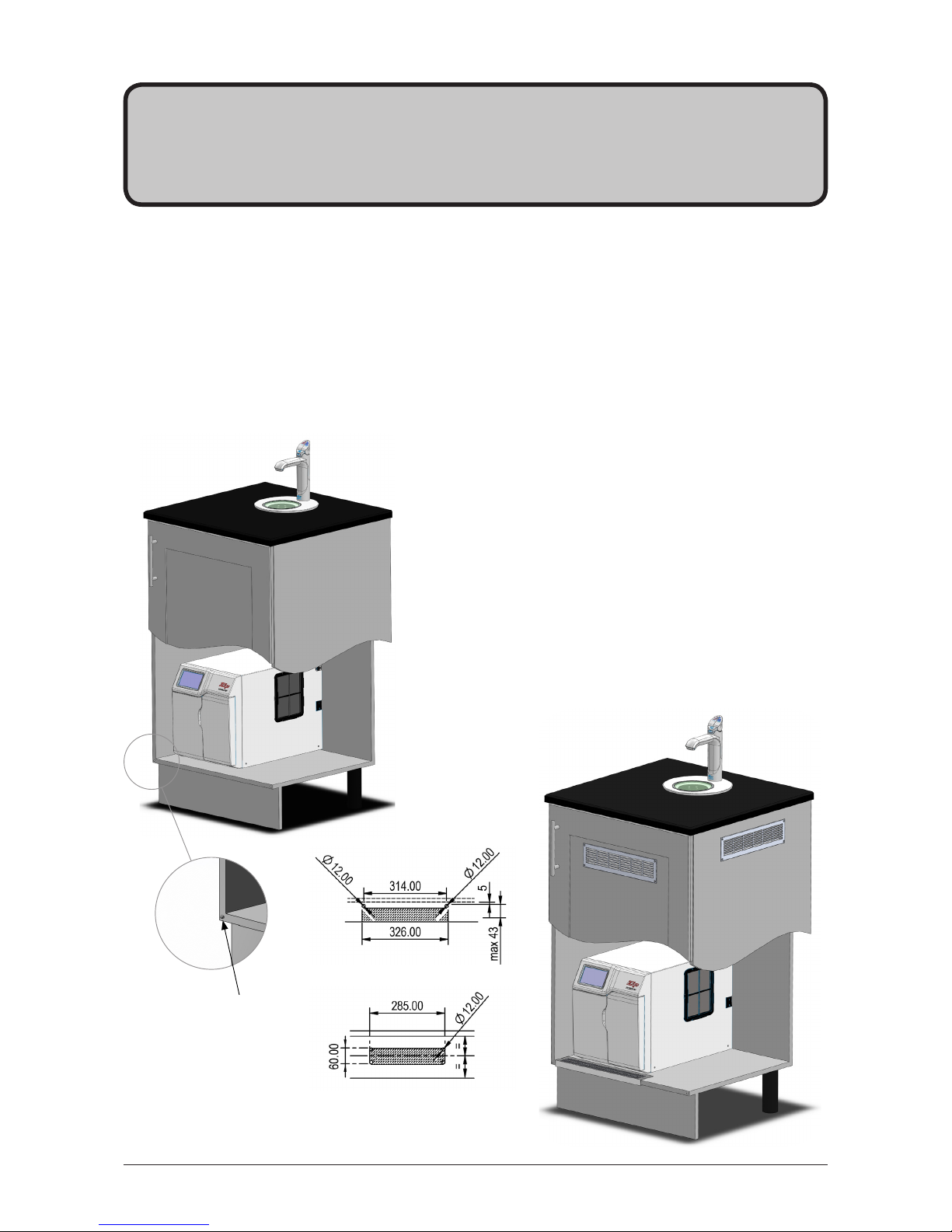
Section 1
Ventilation
1.3 Alternative arrangement
• For high use applications where the cupboard space
temperature is near 350C or higher, the vent kit supplied can be
used to provide further ventilation by convection.
Note The vent kit has to be installed in a way that allows air
to be drawn in from the bottom of the cupboard and expelled
through the top of the cupboard. The outlet vent should
be towards the top of the door (position A1) or side of the
cupboard (position A2).
(Where possible air inlet vent and the air outlet vent should be
positioned at
opposite ends
of the same
cupboard
space).
1.1 Ventilation for all models
• The clearance envelope dimensions stated in the specification sheets and installation instructions must
be observed.
• Adequate ventilation must be provided to ensure that the cupboard space temperature does not exceed
350C.
1.2 Preferred arrangements
4mm door buffers (at the four corners of each door) supplied with the Command-Centre
TM
should be used to
provide adequate ventilation in normal usage, see illustration below.
Door buffer
A1
A2
B
Vent cut-out details
A1 or A2 Air outlet vent
B Air inlet vent
Note Flat outlet vent
detail shown, louvred
outlet vent also supplied.
Page 12
Page 12 of 20 804052UK - Residential chilled and sparkling installation instructions - Sept 2016 - v3.02
Section 2
CO2 Cylinder
STORAGE WARNING
WARNING! The cylinder ( containing 1kg of CO2 ) should be installed in a well ventilated area
of area no less than 38m3.
If more than 1 gas cylinder containing 1kg of CO2 is present within the same location, the recommended
ventilation area should be in proportion to the number of gas cylinders stored in that location.
A ventilated area in a non-enclosed area which could include the kitchen, living room etc.
See gas cylinder and MSDS sheet for complete list of warnings.
2.1 Secure the cylinder
Secure the gas cylinder supplied to a suitable wall, within 1 metre of the Command-CentreTM, in an upright
position. This is undertaken by screwing the metal bar holding the hook-and-loop strap to a cupboard wall,
200mm above the floor or base of the cupboard. Make sure the gas cylinder can stand in place before
securing to the wall. Due to regulatory requirements the gas cylinder must be stored securely and in an
upright position.
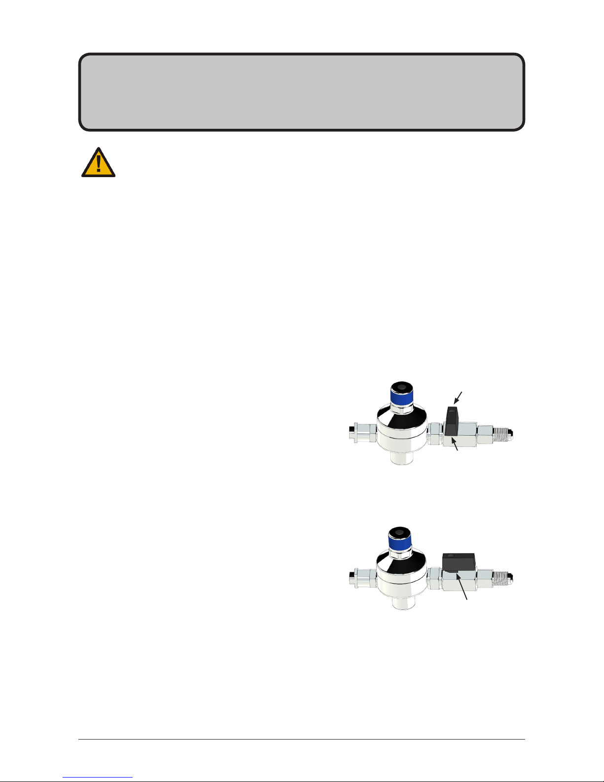
2.2 Connect the regulator
Remove the gas cylinder from the strap. Make sure the regulator
knob is turned fully clockwise to the end-stop before fitting.
Screw the regulator (clockwise) onto the cylinder. Be aware that
some CO2 may be discharged from the connection between the
cylinder and the regulator when assembled together. Any CO2
released will be cold. Screw on the regulator to stop this leakage.
Note The leaking CO2 will be cold.
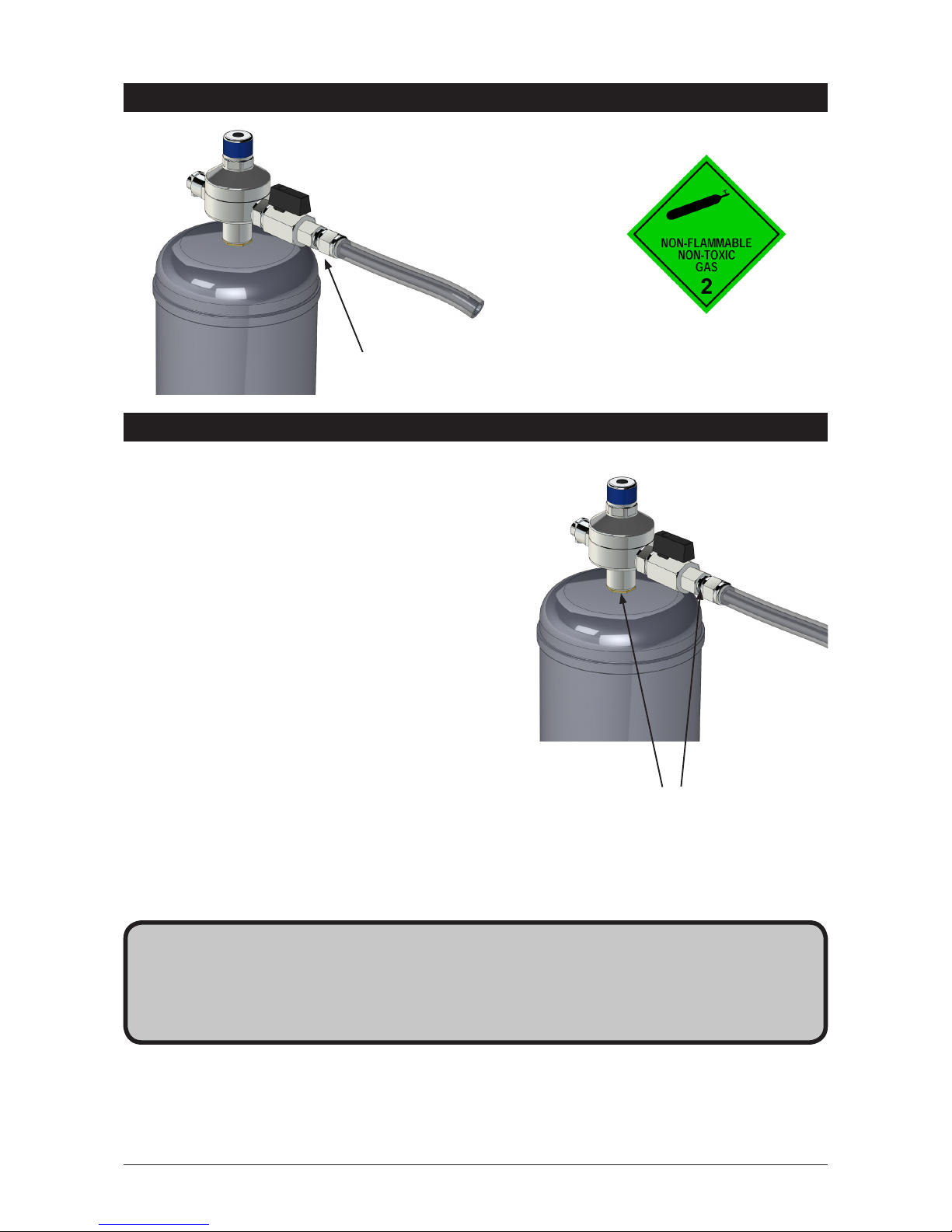
2.3 Connect the gas hose
Connect the threaded end of the braided gas hose to the
regulator. Then connect the push fit fitting to the top of the
Command-CentreTM via connection marked ‘CO2 IN’.
To turn the gas on, rotate the regulator knob anti - clockwise to
the end stop.
2.4 Test for gas leaks
Using soapy water perform a leak test. Apply the soapy water
to the gas connections using a sponge or brush. If any bubbles
appear and grow, there is a gas leak at the connection. Clean away the soapy residue and tighten or refit the
leaking connection. Make sure the gas is turned off when tightening or refitting the leaking connection.
Refit the gas cylinder to the hook-and-loop strap. Ensure the cylinder is in an upright position.
Turn the knob fully
clockwise before fitting
the regulator
Closed
Open
Page 13
804052UK - Residential chilled and sparkling installation instructions - Sept 2016 - v3.02 Page 13 of 20
3.1 Braided hose fitting
Install the mains water braided hoses to the Command-CentreTM before locating in place.
Section 3
Command-CentreTM installation
After replacing a cylinder or after making a
gas connection, perform a leak test to check for
gas leaks between regulator and cylinder, and between regulator
and braided hose.
Stage 1
1. Turn the gas off.
2. Using soapy water applied with a sponge, or with a
brush, cover all of the gas joints with a liberal
amount of suds.
Stage 2
1. Turn the gas on.
2. Inspect the joints for leaks.
3. If any bubbles appear to grow, the joint will need to be
resealed and tested again.
CO2 Regulator
Leak Test
Note When removing hose, take care not to
lose plastic olive from the fitting.
Test for leaks at these two points
Page 14
Page 14 of 20 804052UK - Residential chilled and sparkling installation instructions - Sept 2016 - v3.02
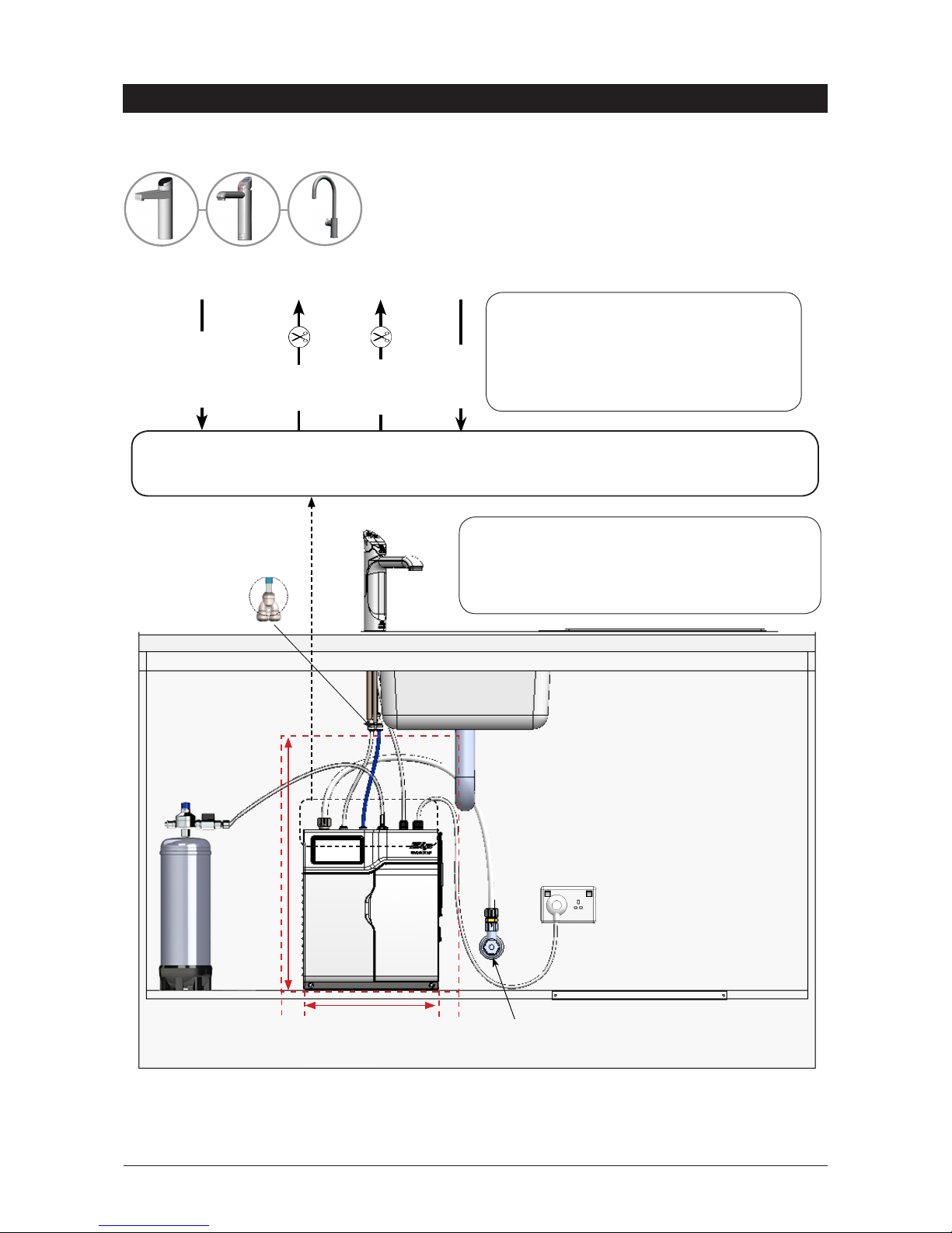
Installation instructions
3.2 Chilled and sparkling HydroTap®G4 models (for Arc / Cube, also refer to the tube kit assembly
instructions supplied with the tap head).
Arc / Cube
Elite Classic
GAS IN
WHITE
POWER
CABLE
USB
MAINS
IN
SPARKLING
OUT
CO2
IN
BLUE
Note All plastic / silicon tubes must be trimmed
to size. They must have a constant fall to the
Command-CentreTM.The blue chilled and white
sparkling pipes must be insulated with the
sleeving provided.
CHILLED
OUT
Note Mains hose length is 750mm
Electrical power cable length is 3.0m nom.
Position the Command-CentreTM according to the hose
and cable lengths supplied.
BRAIDED
External cold isolation valve
(not supplied)
535mm
280mm
50mm
50mm
Clearance
envelope
(Supplied)
Note Neither the braided hoses or the tubes supplied with the tap can be lengthened. Take time to consider
hose lengths when determining the mounting positions for the different options, also ensure that the chilled
and sparkling pipes are covered with the insulation provided.
Page 15
804052UK - Residential chilled and sparkling installation instructions - Sept 2016 - v3.02 Page 15 of 20
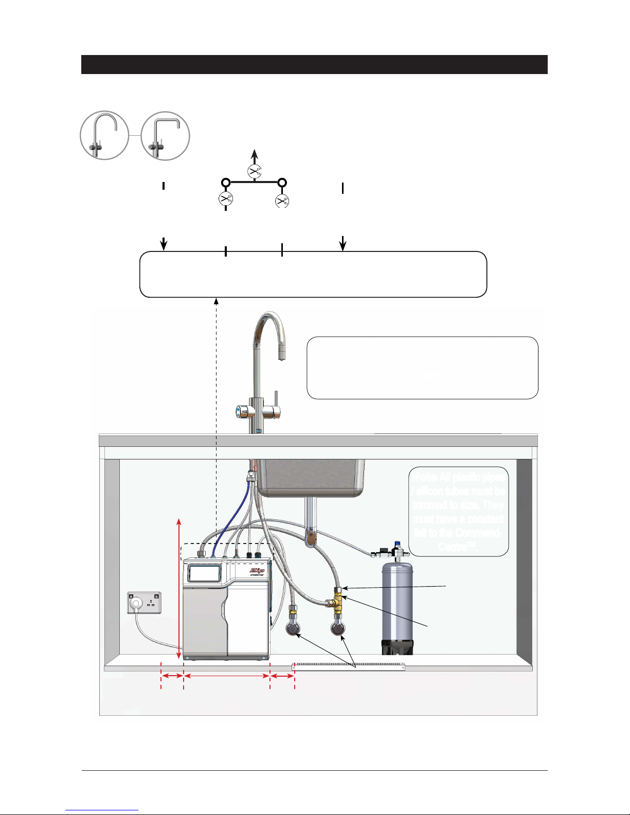
GAS IN
Installation instructions
Note The connection hoses supplied with the tap CANNOT be lengthened, chilled pipes must be insulated
with the insulation provided.
T-piece
(supplied)
280mm
50mm
50mm
535mm
Clearance
Envelope
Note Mains hose length is 750mm.
Electrical power cable length is 3.0m nom.
Position the Command-CentreTM according to the
hose and cable lengths supplied.
3.3 Chilled, sparkling and mixed hot & cold
Celsius Arc
BRAIDED
POWER
CABLE
USBMAINS
IN
CHILLED
OUTLET
WHITE
SPARKLING
OUTLET
BLUE
Note All plastic pipes
/ silicon tubes must be
trimmed to size. They
must have a constant
fall to the Command-
CentreTM.
External HOT and COLD
isolation valves
(not supplied)
Male to male adaptor
to T-piece
(supplied)
CO2
IN
Celsius Cube
Page 16
Page 16 of 20 804052UK - Residential chilled and sparkling installation instructions - Sept 2016 - v3.02
The HydroTap®G4 is now ready to be commissioned.
•
Turn on the power, gas and water and check for any leaks.
•
Familiarise yourself with the operation of the HydroTap®G4 in preparation for use (see user manual).
•
Follow the installation instructions below (and review section C of the user manual).
•
After commissioning, the system may be customised by selecting further options in section G Settings, of the user manual.
Section 4
Commissioning
Commissioning
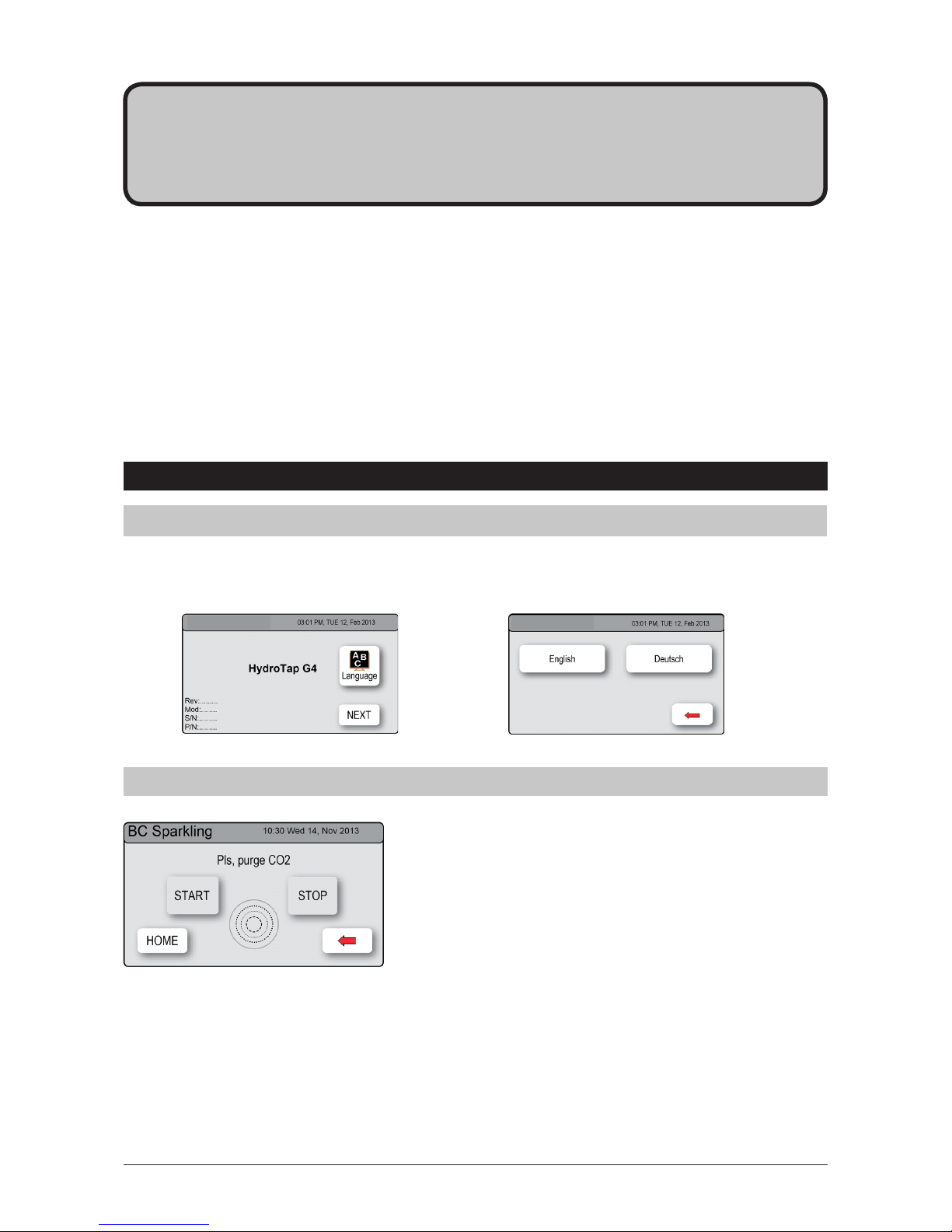
• Press the [MENU] button for main menu.
• Press the [Install] button.
• Press the [Purge CO] button.
• In the next screen, press the [START]
button to commence the purging process.
• You will hear the CO2 gas running through
the tap.
• Run for 10 seconds to fully purge the CO2.
• Press the [STOP] button to stop the purge.
• Press [Next] for filter flush screen.
4.2 - CO2 purge
4.1 - Select the language
Initial commissioning screen
Language selection screen
Zip BC Sparkling
Zip BC Sparkling
Page 17
804052UK - Residential chilled and sparkling installation instructions - Sept 2016 - v3.02 Page 17 of 20
Commissioning
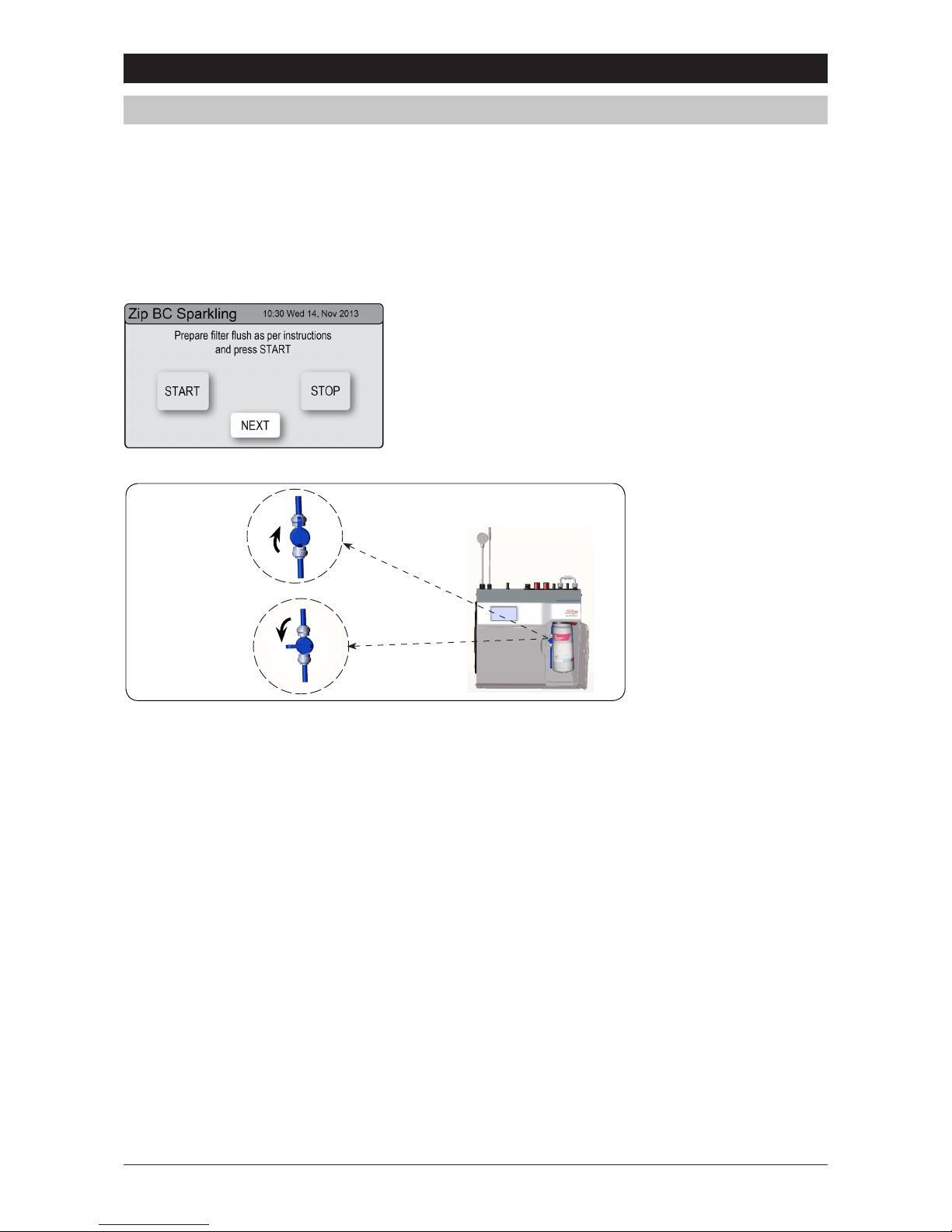
• Press [START] / [STOP] button to start and stop the filter
flush.
• Open the flush stop cock.
• Allow at least 10 litres of water to flush through the filter.
• Once the filter flush is finished, Close the stop cock then
press [STOP] to end filter flush mode.
OPEN Position
CLOSED Position
ON
OFF
G4 HydroTap Filter Flush Menu
Stop cock
operation
Have a bucket or similar container (not supplied) at the ready to hold a quantity of water that will be ejected
while the filter flush mode is in operation. Open the filter access door on the front of the HydroTap®G4 and
the filter cartridge will be exposed. Located to the rear right hand side of the cartridge is a flush line, approx
600mm long and the flush line stop cock. Place the free end of the flush line into the bucket or container (not
supplied).
Note
At first commissioning, the system will select the filter flush screen automatically after CO2 purge.
4.3 - Filter flush
Page 18
Page 18 of 20 804052UK - Residential chilled and sparkling installation instructions - Sept 2016 - v3.02
Trouble shooting
End of life disposal
The use of this crossed out wheeled bin logo indicates that this product needs to be disposed of separately to any
other household waste.
Within each of the European Union member countries, provisions have been made for collection and recycling of
unwanted electrical and electronic equipment. In order to help preserve our environment we ask that you dispose of
this product correctly. Please contact Zip Customer Service on 0345 6 005 005 for advice.
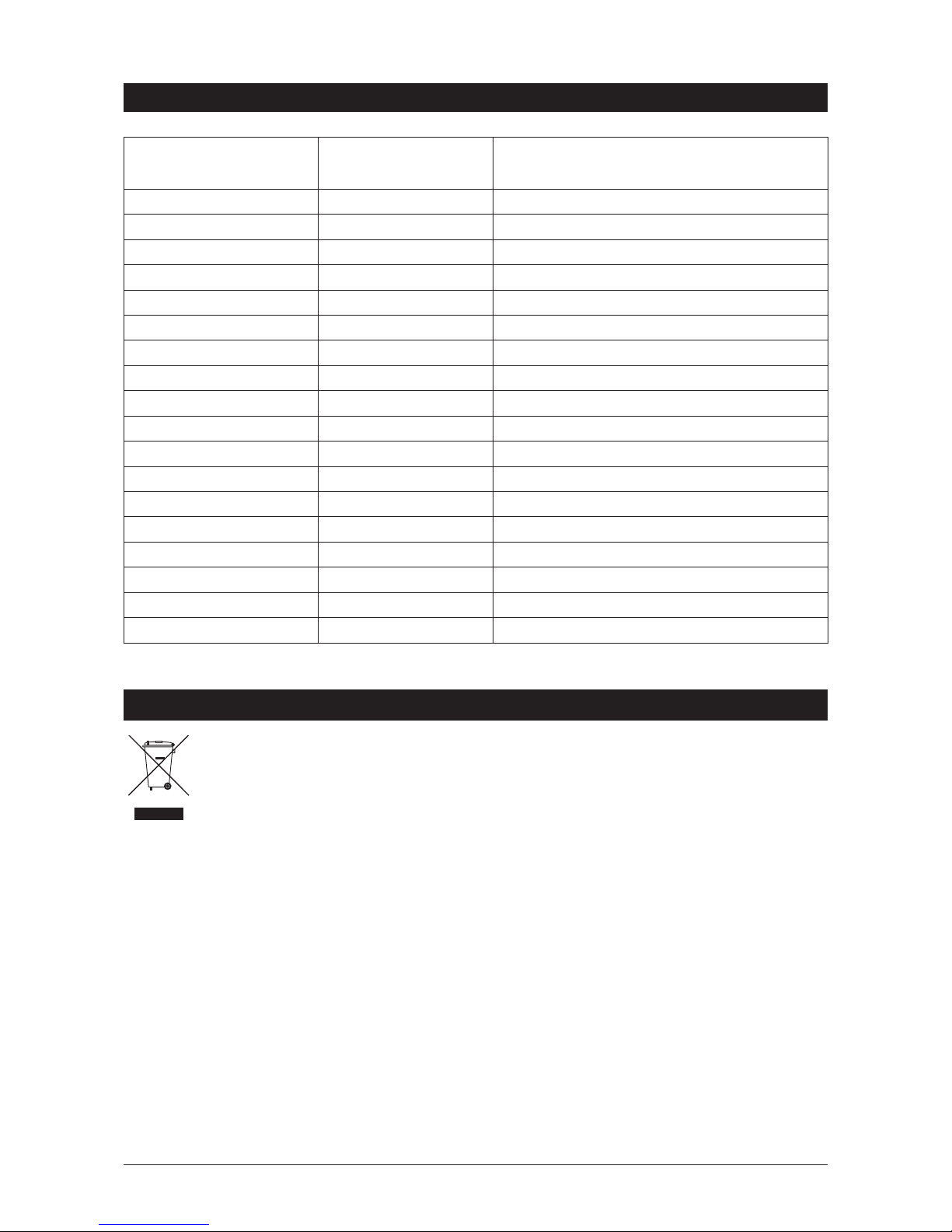
System fault
message
Possible cause Solutions
Power Board Fault Electrical disruption Check power supply and all fuses
Interface Fault Internal fault Call Zip service
Level Board Fault Internal fault Call Zip service
Condenser Screen Blocked Blocked air filter Remove blockage / clean filter / check user guide
Water leak, Isolate Mains Water leak Turn off mains water supply / call for service
Compressor Over Run Compressor too hot Check ventilation
Water Supply Failure No water Check water supply is turned on
Cold Sensor Open Internal fault Call Zip service
Cold Sensor Closed Internal fault Call Zip service
Flood Sensor Open Internal fault Call Zip service
Condenser Sensor Closed Internal fault Check ventilation / Call Zip service
Condenser Sensor Open Internal fault Check ventilation / Call Zip service
Compressor. Driver Fault No chilled water Call Zip service
A DC Pump is faulty Internal fault Call Zip Service
Condenser Overtemp Blocked air filter Remove blockage / Clean filter / check user guide
Comp Fuse/Driver Fault Internal fault Call Zip service
Flash Mem corrupted Internal fault Call Zip Service
Flow Sensor Fault Internal fault Call Zip Service
Call an electrician, a plumber, or Zip on 0345 6 005 005 for assistance, service, spare parts or enquiries.
Page 19

804052UK - Residential chilled and sparkling installation instructions - Sept 2016 - v3.02 Page 19 of 20
Warranty
Certain warranties may be implied by law into your contract with Zip. The warranty provided below is
additional to these implied warranties and nothing set out below shall limit your statutory rights or rights at law.
Zip Heaters (UK) warrants that, should the hot tank (boiling models) fail within five years of installation subject
to satisfactory maintenance and registration of the product, or any part fail within three years of installation,
the part will be repaired or replaced free of charge by Zip, its distributor or service provider, (except as set out
below), provided the appliance is installed and used strictly in accordance with the instructions supplied, and
that failure is not due to accident, misuse, abuse, unsuitable water conditions, or to any alteration, modification
or repair by any party not expressly nominated by Zip.
No costs are payable by the customer other than any mileage or travelling-time charges incurred by a Zip
service provider or the cost of removal, cartage and re-installation of any component of the appliance if it
needs to be returned for repair to Zip or its distributor.
This warranty does not cover damage resulting from non-operation of the appliance, the use of non authorised
parts or consequential damage to any other goods, furnishings or property.
No warranty applies to the life of any filtration cartridge installed with the appliance as cartridge life may vary
according to water quality and the rate of water consumption.
Zip does not exclude, restrict or modify any liability that cannot be excluded, restricted or modified or which
cannot, except to a limited extent, be excluded, restricted or modified as between the owner or user and Zip
under the laws applicable.
Furthermore this warranty does not displace any statutory warranty, but, to the extent to which Zip is entitled
to do so, the liability of Zip under any statutory warranty will be limited at Zip’s option to the replacement of the
appliance or supply of equivalent appliance, the payment of the cost of replacing the appliance or acquiring an
equivalent appliance, or the payment of the cost of having the appliance repaired or the repair of the
appliance.
HydroTap®G4 residential models are designed specifically for use in a domestic environment and
inappropriate installations such as in a commercial location will invalidate the warranty.
Registering your purchase.
Registering your Zip installation on the Zip website may help to establish date of installation should it become
necessary to service the appliance under terms of the Zip warranty. To register your installation go to
www.zipwater.com/uk and look under the heading “Warranty”.
Page 20

Page 20 of 20 804052UK - Residential chilled and sparkling installation instructions - Sept 2016 - v3.02
Contact details
The standard cup referred to in this publication is 167 ml (6 fl oz).
The standard glass is 200 ml (7 fl oz).
The terms “Zip” and “HydroTap” are registered trade marks of Zip Heaters (Aust) Pty Ltd.
Zipproductsdescribedinthispublicationaremanufacturedunderoneormoreofthefollowingpatents:AU675601,
AU637412, AU635979, GB0422305, GB2065848, US4354049, US5103859, US5099825 and SA2006/08043. Other
patents are in force and patent applications are pending.
Head office
Zip Water UK
14 Bertie Ward Way
Dereham
Norfolk
NR19 1TE
Website:www.zipwater.com/uk
Email:[email protected]
Facsimile:01362692448
Telephone:03456005005
 Loading...