

Installation and Operating Instructions
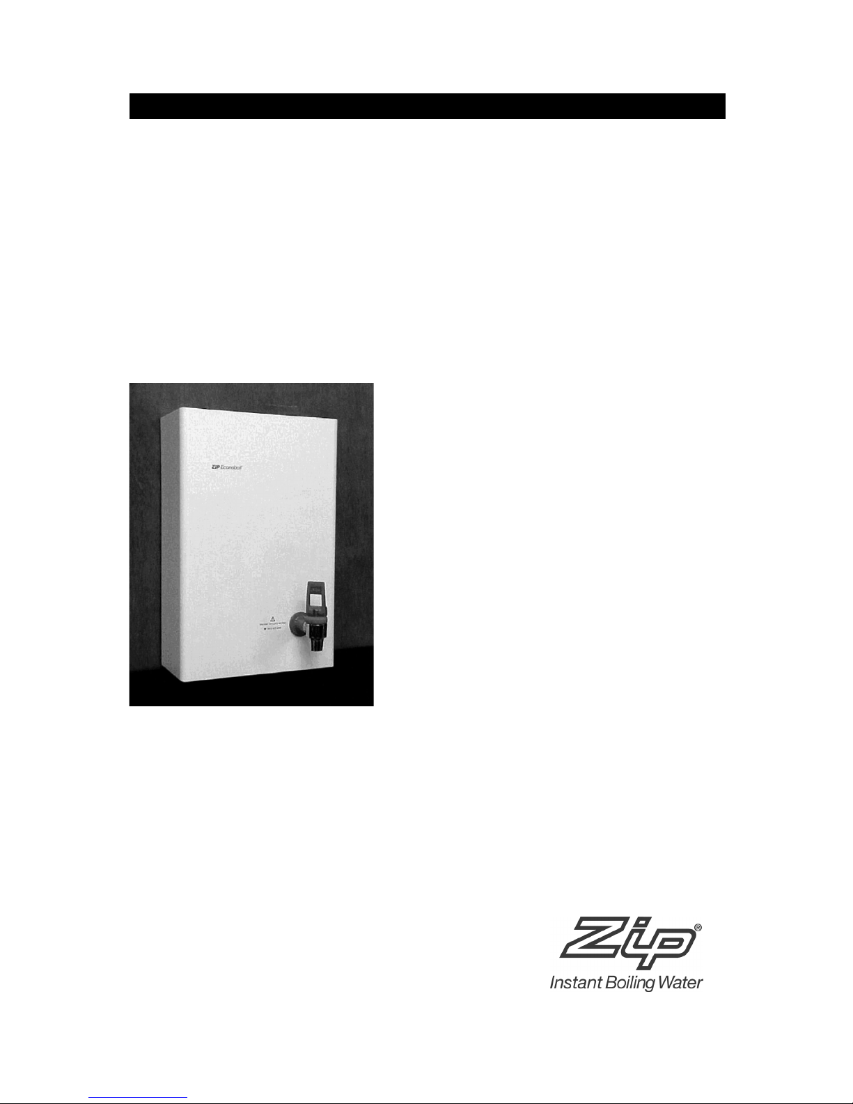
Zip Econoboil
Budget priced instant boiling water for canteens and kitchens.
03592 Zip Econoboil 2.5 litre White HS403
05592 Zip Econoboil 5.0 litre White HS405
07592 Zip Econoboil 7.5 litre White HS407

Page 2 of 12 Zip Econoboil Installation & Operating Instructions - 82790 - January 2004

Zip Econoboil - Installation & Operating Instructions - 82790 - January 2004 Page 3 of 12
Table of Contents
Read These Warnings First . . . . . . . . . . . . . .4
Installation Requirements . . . . . . . . . . . . . . .4
Installation Procedures . . . . . . . . . . . . . . . . .5
Step 1 – Positioning . . . . . . . .5
Step 2 – Fastening . . . . . . . . .5
Step 3 – Connecting . . . . . . .6
a) Plumbing . . . . . . . .6
b) Venting . . . . . . . . .6
c) Electrical . . . . . . . .7
Step 4 – Assembling . . . . . . .7
Step 5 – Commissioning . . . .7
Operating Procedures . . . . . . . . . . . . . . . . . .7
Tap Operation . . . . . . . . . . . .7
Cleaning Case . . . . . . . . . . . .8
Earthing Continuity Verification . . . . . . . . . . .8
Problem Solving . . . . . . . . . . . . . . . . . . . . . .8
Wall Mounting Template
Dimensions & Electrical Diagram . . . . . . . . . .9
Temperature Setting . . . . . . . . . . . . . . . . . . .9
Spare Parts List . . . . . . . . . . . . . . . . . . . . . . .10
Exploded View Diagram . . . . . . . . . . . . . . . . .11
Warranty Information . . . . . . . . . . . . . . . . . . .12

Page 4 of 12 Zip Econoboil Installation & Operating Instructions - 82790 - January 2004
Read These Warnings First
Please read all installation requirements, installation procedures and precautions
before installing any Zip Econoboil instant boiling water heater.
Never attempt to install any Zip Econoboil instant boiling water heater without
reading all of the applicable instructions.
In some hard water areas where mineral scale accumulation in the boiling
chamber of the Zip Econoboil may become a problem, consideration should be
given to the maintenance required. A suitable form of water treatment may be
necessary.
The cold water supply to this appliance must be potable and fall within your local
authorities guidelines.
The Zip Econoboil instant boiling water heater is not intended for use by young
children or infirm people without supervision.
Young children should be prevented from having access to ensure that they are
not able to use or play with the heater.
If the installation site is located more than 1000 metres above sea level, the
installer should contact Zip for high altitude settings.
This appliance must be earthed. If the power supply cord is damaged it must be
replaced by a qualified electrician.
Do not remove the cover of the heater under any circumstances without first
isolating the heater from the power supply.
Do not use strong, corrosive or abrasive cleaners to clean the case of the heater.
Frost protection: If this heater is located where ambient air temperature could
fall below 5ºC when the heater is not in use, do not turn off the appliance
electrically. This safeguard does not offer the same protection to the connecting
pipework and fittings.
The ambient temperatures this unit should operate with is 5ºC - 50ºC.
This heater is intended only for indoor use and should never be installed
outdoors or be exposed to the elements of nature.
This unit must not be positioned in an area that may be cleaned by a water jet.
This unit must not be cleaned by a water jet.
Before installing, ensure that the following are available:
a) Sufficient space to position the heater so there is at least 150 mm
clearance above the heater for service access, 65 mm to its left and
20 mm to its right – the tap outlet usually should be positioned at least
200 mm above a draining board or drip tray.
b) Power supply 13 amp fused spur for connection to the heater via a double
pole fused sur with a minimum break rating of 13 amps.
For units with 3.6 Kw element (25 ltr) or multi element units (40 ltr) an
isolating switch in the fixed wiring and attached to a secure surface is
required. This switch must provide all-pole disconnection and a contact
seperation of at least 3 mm installed in accordance with wiring rules.
c) Cold water supply with a minimum working pressure of 1.5 bar and a
maximum working pressure of 10 bar connected via an isolation valve.
Installation Requirements
 Loading...