

Page 1
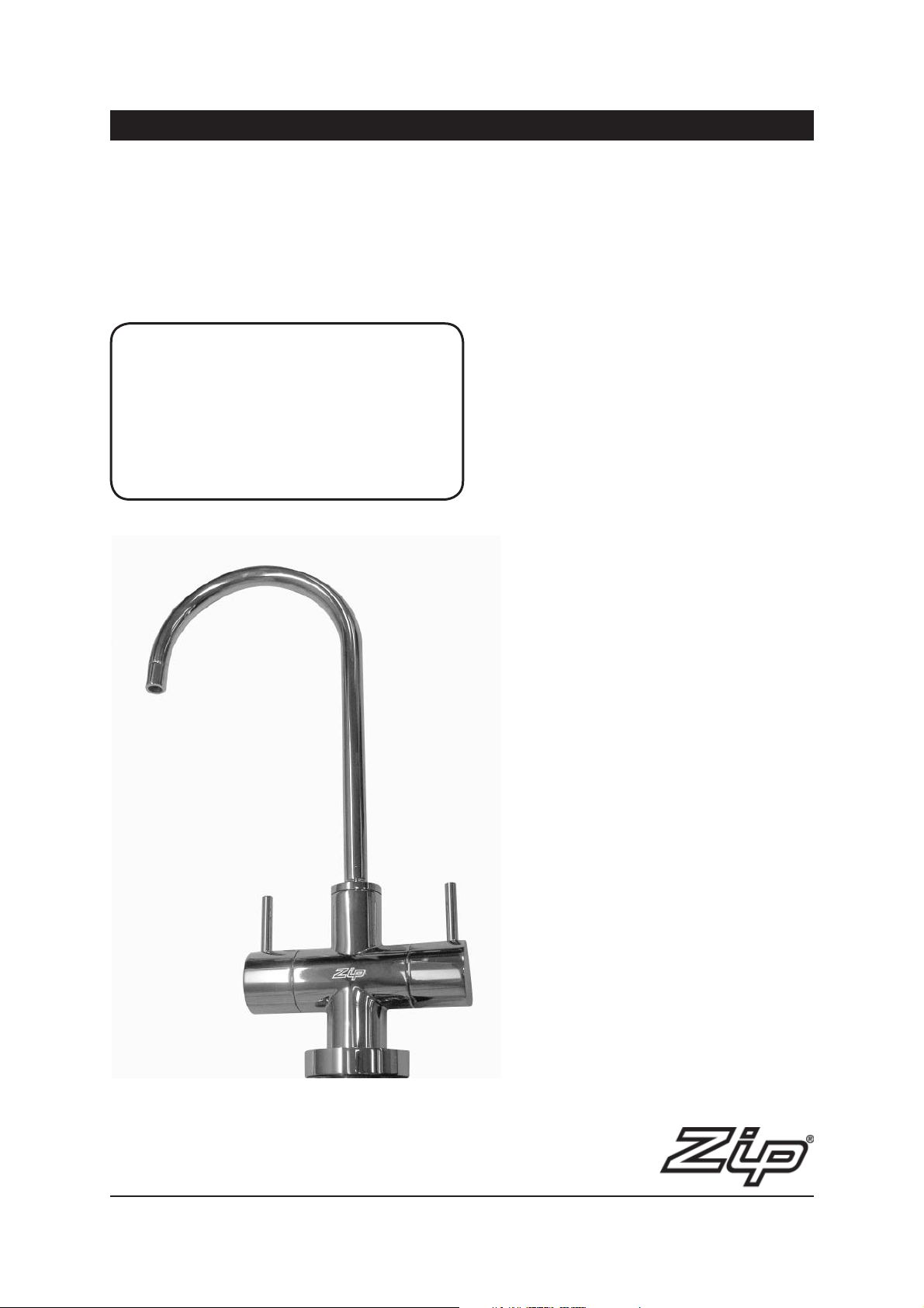
Installation and Operating Instructions
Zip Chilltap Extra
Filtered Chilled and Ambient drinking water for the home
Affix Model Number Label Here
800043UK
®
Chill Tap - Installation & Operating Instructions - 800043UK - August 2011 v1.03 Page 1 of 8
Page 2
# Read These Warnings First
# Section Heading
• Please read all installation requirements, installation procedures and precautions before
installing any Zip Chilltap.
• Never attempt to install any Zip Chilltap without reading all of the applicable instructions.
• All electrical connections must comply with UK Electrical Regulations.
• This appliance is not designed for use by young children or infirm people without supervision.
• Young children should be prevented from having access to ensure they are not able to use or
play with the chiller.
• This appliance must be earthed.
• If the power supply cable is damaged it must be replaced by a Zip Service Provider or a
qualified electrician.
• The Power cable and power outlet must be in a safe and accessible position after installation.
• Do not remove the cover of the appliance under any circumstances without first isolating the
appliance from the power supply.
• This unit is designed for indoor use and must not be installed outdoors or exposed to the
elements of nature.
• This unit must not be positioned in an area that may be cleaned by a water jet.
• This unit must not be cleaned by a water jet.
Precautions
The plumbing installation must be done in accordance with UK Water Regulations and these
Installation Instructions.
As the installer, it is your responsibility to supply (if necessary) and install all valves as required by
current regulations and relevant standards.
Installation requirements
• Power supply 220-240V AC 50Hz for connection via a 13A plug or fused
spur.
• Operating temperatures 5º C - 35º C.
• Water pressure 70 kPa - 700 kPa (0.7 bar to 7 bar)
NOTE: For best results we recommend a minimum static pressure of 200 kPa (2 bar)
End of life disposal
The use of this crossed out wheeled bin logo indicates that this product needs
to be disposed of separately to any other household waste.
Within each of the European Union member countries, provisions have been
made for the collection and recycling of unwanted electrical and electronic
equipment.
In order to help preserve our environment we ask that you dispose of this
product correctly. Please contact Zip Customer service for advice on 0845 602
4533.
Page 2 of 8 Chill Tap - Installation & Operating Instructions - 800043UK - August 2011 v1.03
Page 3
Domestic Models Covered by these instructions
These installation instructions are for the Zip UK Domestic DOMCT1
Chilled Water Capacity:
60 glasses per hour
Total Rating: 245W
Chilled Chamber: 1.8L
Chilled Water Temperature: 7º C - 12º C
Note: the Glass measurement = 200mls.
When correctly installed, operated and maintained in accordance with these
instructions, the Zip Chilltap is intended to deliver filtered chilled water for
domestic consumption.
Model Height
mm (inch)
DOMCT1 377 (14.8) 253 (10.0) 353 (13.9) 17.8 19.8
Depth
mm (inch)
Width
mm (inch)
# Installation Instructions
Installing the Chiller
Sit the chiller unit into the cupboard as close to the proposed outlet tap position
as is possible, to minimise the length of tubing exposed between the chiller unit
and the tap.
Allow at least 50 mm around the chiller unit to permit free airflow. Both the top
and the front of the chiller must remain accessible for servicing purposes.
Installing the Tap
Position and install the tap at the back of the sink or on the Font, where there is
a minimum 52 mm wide flat area within the draining area of the sink.
NOTE: The diameter of the base of the tap is 50mm.
Make sure the selected position allows the tap spout to overhang the sink bowl.
Weight empty
kg’s lbs
Weight full
kg’s lbs
Use a 35 mm sheet metal punch to create a neat hole without burrs.
Remove the large nut with the brass and rubber washers from the base of the
tap, leaving the rubber-sealing ring (o-ring) in place.
Fit the tap and seal to the sink, oriented so both the operating levers are easily
accessible.
Slide first, the rubber washer and then the brass washer, followed by the nut,
over the plastic tubes from under the sink, and tighten the nut to secure the tap
firmly into place.
Chill Tap - Installation & Operating Instructions - 800043UK - August 2011 v1.03 Page 3 of 8
Page 4
# Installation Instructions continued
Connecting:
NOTE: You must separately supply and install an isolating valve in the supply
line before the connection to the product.
Minimum supply pressure must be 70kPa (0.7 bar). For best results we
recommend a minimum static pressure of 200 kPa (2 bar). If the pressure
exceeds 700 kPa (7 bar), you must also supply and install a 350 kPa (3.5 bar)
pressure-limiting valve.
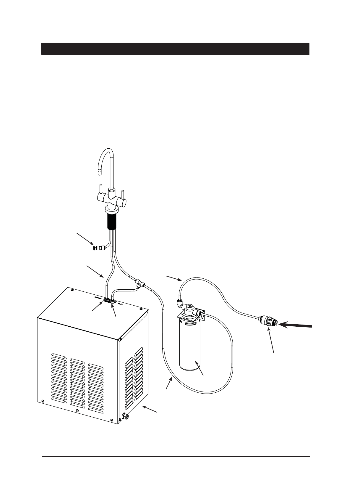
Ambient Connection (with chiller inlet branch line):
With 1/4” white tubing, Connect the JG Nut + Straight Connector Assembly to
the inlet of the filter. From the outlet of the filter, connect the 1/4” white tubing
from the tap, via the Tee piece supplied. The branch line from this Tee piece
must connect to the JG fitting marked INLET on the top right rear of the chiller.
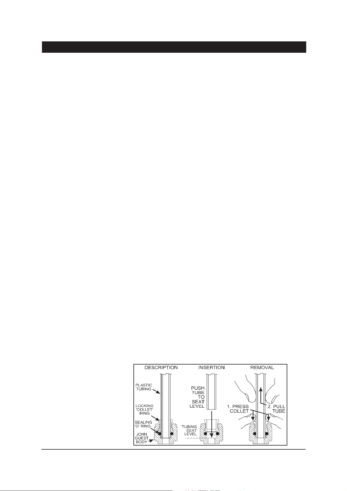
Cut excess off to ensure a neat job. Make sure all connections to John Guest
fittings are pushed in past the “O”ring to full depth, at least 15-16mm.
Chiller connection:
Similarly, use the Blue tube, to connect to the JG fitting marked OUTLET on
the top left rear of the chiller unit. Insulate the 1/4” BLUE tube with the loose
length of the pipe insulation, cut both pieces to correct length.
Locate the 1/4” Clear (vent) tube from the tap and connect this to the John
Guest connector. Ensure JG Plug is also fitted to connector. Make sure all
connections to John Guest fittings are pushed in past the “O”ring to full depth,
at least 15-16mm.
The Tap connection is now complete.
Take care, when bending rigid plastic tubing, to prevent it from kinking or
crushing around a bend. As it is plastic tubing containing water under mains
pressure, be careful not to nick, scratch or damage it during installation.
Cut the tube squarely with a sharp knife or tube cutter. Shake out and remove
any swarf and debris.
Ensure there is adequate ventilation available through the cupboard. If there
is inadequate ventilation, and the cupboard temperature rises to above 40°C,
the chiller may become damaged and malfunction which will void the product
warranty.
There must be a minimum 168cm2 of cupboard cross-flow ventilation.
Suitable holes or vents will need to be cut into the cupboard and door.
For safe operation, thoroughly flush the water through after non-use periods
longer than 12 hours.
John Guest connections
Page 4 of 8 Chill Tap - Installation & Operating Instructions - 800043UK - August 2011 v1.03
Page 5
# Installation Instructions continued
# Section Heading
Filter cartridges should be replaced at least every 6-12 months, or sooner if
you notice:
A. A persistent reduction in water pressure from the product, or;
B. An unpleasant taste or odour in the water.
Not changing the cartridges when required may cause the water to become
biologically unsafe.
Commissioning
Clip the tubing in the cupboard. After the appliance is installed and
connected, turn “ON” the water supply. Check all connections for leaks.
Repair any leaks found.
The filter, chiller and tubing will be full of air until purged. Rotate the
operating lever on the appliance outlet tap for a minimum of five minutes until
all of the air has been purged from the system.
Connect the unit to the electrical supply. Do NOT turn “ON” until after the unit
is purged.
Wipe clean and dry the area.
Dispose of packaging wisely.
JG Connector
Blue
Outlet
White
Incoming water supply
Inlet
JG Nut+Straight Connector Assembly
Filter
Blue
Under Bench Chiller
Chill Tap - Installation & Operating Instructions - 800043UK - August 2011 v1.03 Page 5 of 8
Page 6
# Operating Procedures
Operation:
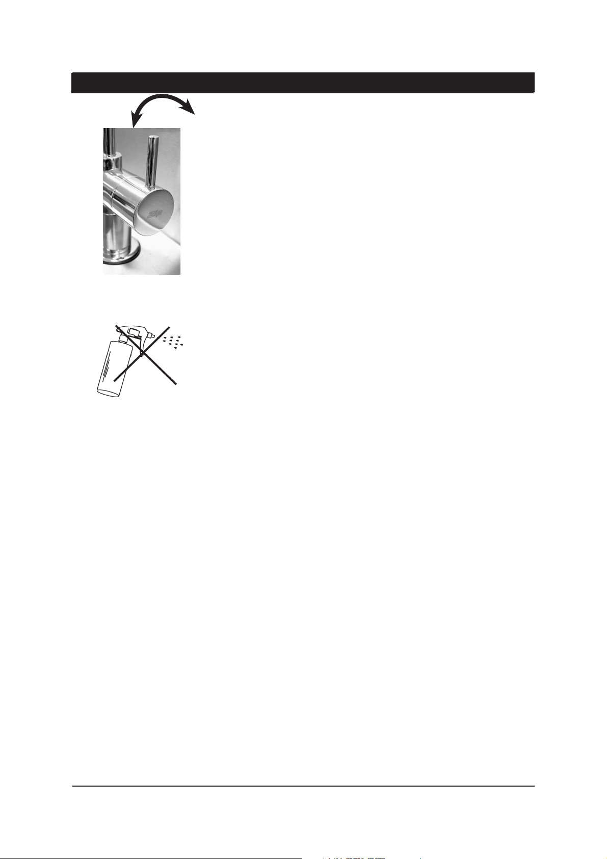
ROTATE
The lever on the right is used for Chilled filtered water and the other, on the left,
is used for Ambient filtered water.
Chilled water is obtained by rotating the lever on the right, to a horizontal
position. The water is chilled by a refrigeration unit fitted within the cabinet,
under the sink.
With the tap, you can obtain chilled water within the rated capacity, for as long
as you leave the lever in the open (horizontal) position. When finished, return
the lever to the OFF (upright) position.
Ambient water is obtained in the same way as the chilled water, by rotating the
lever on the left hand side of the tap .
Cleaning
Never use strong, corrosive or abrasive cleaning materials on the Zip Chilltap.
Wipe clean the outer surfaces with a sponge or a soft cloth using a mild soap
and water.
The louvres on the sides of the chiller unit need to be kept free of dust and lint
to permit free flow of air through the vents. They should be checked regularly,
at least monthly, and dusted or vacuumed.
Filter Replacement
The Zip Chilltap Under Counter Chiller has a separate filtration system
connected to the incoming water supply line, and which may be located within
the same cupboard as the chiller unit.
For safe operation, the filter cartridge should be replaced every 6-12 months, or
earlier if you notice a persistent reduction in water pressure from the appliance
or an unpleasant taste or odour in the water.
WARNING
Not changing filtration cartridges when required, may cause the water to
become biologically unsafe. Make an entry in your diary to check the water
quality of the Chilltap at least six months after installation and after every
subsequent filter change.
Use only genuine Zip replacement filter catridge ZT002. Replacement filter
cartridges can be obtained through plumbing suppliers or directly from Zip.
Replacement instructions come with the filter cartridges.
Before attempting to disconnect or remove the filter cartridge from the housing,
isolate (turn off) the water supply prior to the filter system, and then relieve the
system pressure by operating the chilled water outlet tap until the water ceases
to flow.
Service
There are no user serviceable parts but there are dangerous voltages present
within the unit. All service work must only be carried out by a suitably qualified
and experienced service person.
Before calling for service, check that both the water and electricity supplies are
turned ‘ON’ and OK.
For technical assistance and service support contact Zip on 0800 077 8302.
Page 6 of 8 Chill Tap - Installation & Operating Instructions - 800043UK - August 2011 v1.03
Page 7
# Installation Diagrams
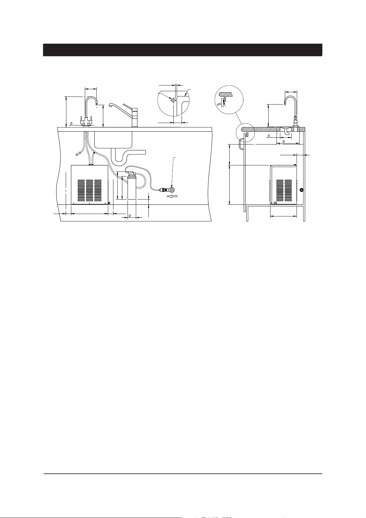
DOMCT1 model installation
Min
Max
15
Sink
80
295
113
Tap hole ø35mm
213
30
Air gap
Buer pad
4mm
113
213.60
108
218.50
Min 50
353
265
Min 50
220
Mains cold water
isolation valve
UK 240V
GPO
79
Min 50
Min 200
377
Min 65
253
Chill Tap - Installation & Operating Instructions - 800043UK - August 2011 v1.03 Page 7 of 8
Page 8
Warranty Information
Certain warranties may be implied by law into your contract with Zip. The warranty provided below is additional to these
implied warranties and nothing set out below shall limit your statutory rights or rights at law.
Zip Heaters (UK) Ltd warrants that, should any part fail within 12 calendar months of installation, that part will be
repaired or replaced free of charge by Zip or its Distributor or Service Provider, except as set out below, provided
the appliance is installed and used strictly in accordance with the instructions supplied, and that failure is not due
to accident, misuse, abuse, unsuitable water conditions, or to any alteration, modification or repair by any party not
expressly nominated by Zip.
No costs are payable by the customer other than any mileage or travelling-time charges incurred by a Zip Service
Provider or the cost of removal, cartage and re-installation of any component of the appliance if it needs to be returned
for repair to Zip or its Distributor.
This warranty does not cover damage resulting from non-operation of the appliance, the use of non authorised parts or
consequential damage to any other goods, furnishings or property.
No warranty applies to the life of any filtration cartridge installed with the appliance as cartridge life may vary according
to water quality and the rate of water consumption.
Zip does not exclude, restrict or modify any liability that cannot be excluded, restricted or modified or which cannot,
except to a limited extent, be excluded, restricted or modified as between the owner or user and Zip under the laws
applicable.
Furthermore, this warranty does not displace any statutory warranty, but, to the extent to which Zip is entitled to do
so, the liability of Zip under any statutory warranty will be limited at Zip’s option to the replacement of the appliance or
supply of equivalent appliance, the payment of the cost of replacing the appliance or acquiring an equivalent appliance,
or the payment of the cost of having the appliance repaired or the repair of the appliance.
Registering Your Purchase
Registering your Zip installation on the Zip website may help to establish date of installation should it become necessary
to service the appliance under terms of the Zip warranty. To register your installation go to www.zipheaters.co.uk and
look under the heading “Warranty”.
As Zip policy is one of continuous product improvement, changes to specifications may be made without prior notice.
Images in this booklet have been modified and may not be true representations of the finished goods.
Zip Heaters (UK) Ltd.
14 Bertie Ward Way
Dereham
Norfolk
NR19 1TE
Customer Service/ Sales Tel: 0845 602 4533
Service/ Technical Support Tel: 0800 077 8302
E-mail: [email protected]
Website: www.zipheaters.co.uk
Chill Tap - Installation & Operating Instructions - 800043UK - August 2011 v1.03 Page 8 of 8
 Loading...