

Page 1
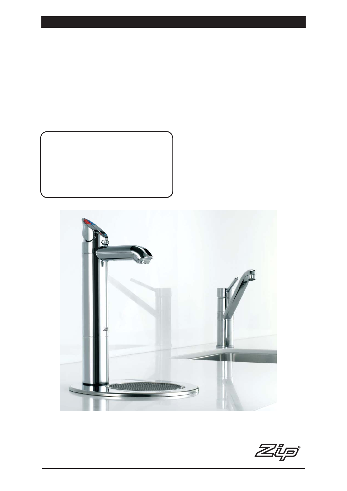
Installation and Operating Instructions
®
Zip HydroTap 4-in-1 and
®
Zip HydroTap 3-in-1
Filtered Boiling and Chilled water plus Hot and Cold water for kitchens and tea rooms.
This Installation Instruction covers the following HydroTap models:
‘BCH’ 4-in-1 series and ‘BH’ 3-in-1 series.
Affix Model Number Label Here
87737UK
HydroTap Installation and Operating Instructions - 87737UK - June 2012 v1.04 Page 1 of 20
Page 2

Contents
Read These Warnings First . . . . . . . . . . . . . . . . . . . . . . . . . . 3
Models Covered by These Instructions. . . . . . . . . . . . . . . . . . 4
Installation Requirements . . . . . . . . . . . . . . . . . . . . . . . . . . .5
Special Tools Required . . . . . . . . . . . . . . . . . . . . . . . . . . . . .5
Installation Procedure . . . . . . . . . . . . . . . . . . . . . . . . . . . . . . 5
Step A - Installing the HydroTap . . . . . . . . . . . . . . . . 5
Step B - Installing / Connecting the Mixer Tap . . . . .6
Step C - Installing the Undersink Unit . . . . . . . . . . . .6
Step D - Connecting the Hydrotap . . . . . . . . . . . . . .7
Step E - Connecting an External Filter . . . . . . . . . . . .7 - 8
Step F - Connecting the Water Supply . . . . . . . . . . . .9
Step G - Testing and Commissioning . . . . . . . . . . . . . 9
Step H - Set Point Adjustment . . . . . . . . . . . . . . . . . . 10
Font Installation Procedure . . . . . . . . . . . . . . . . . . . . . . . . . .11
Operating the Mixer Tap . . . . . . . . . . . . . . . . . . . . . . . . . . . . 11
Operating the Hydrotap . . . . . . . . . . . . . . . . . . . . . . . . . . . . . 12
Filter Replacement. . . . . . . . . . . . . . . . . . . . . . . . . . . . . . . . . 13 - 14
Setting the Energy Saver Timer . . . . . . . . . . . . . . . . . . . . . . .14 - 15
Auxiliary Fan Attachment . . . . . . . . . . . . . . . . . . . . . . . . . . . . 15
Boiling Water Isolation . . . . . . . . . . . . . . . . . . . . . . . . . . . . . .16
Setting Boiling & Chilled Dispensing Times . . . . . . . . . . . . . . 16
Cleaning and Disposal . . . . . . . . . . . . . . . . . . . . . . . . . . . . . .16
Trouble Shooting . . . . . . . . . . . . . . . . . . . . . . . . . . . . . . . . . .17
Mixer Tap Exploded Diagram & Parts. . . . . . . . . . . . . . . . . . . 18
3-in-1 Installation Options . . . . . . . . . . . . . . . . . . . . . . . . . . .19
4-in-1 Installation Options . . . . . . . . . . . . . . . . . . . . . . . . . . .19
Warranty / Contact Information . . . . . . . . . . . . . . . . . . . . . . . 20
Product Description
Hydrotap BH, 3-in-1 and BCH, 4-in-1 models employ the use of selected Hydrotap B and BC assemblies, which have
been factory modified to accept a secondary mixer tap. The mixer tap is connected so that it draws water directly from
the cold water mains as well as from the boiling water storage tank. In this way the combination of the two taps will
allow the user to select water at 4 different temperature ranges. (see estimates below)
For BCH, 4-in-1 models, the main Hydrotap outlet will deliver Boiling and Chilled water and the secondary mixer tap
outlet will deliver Hot and Cold water. Whereas the BH, 3-in-1 models will perform exactly the same, except there is no
chilled water option.
The estimated temperature ranges will be:
Boiling water: 68°C - 98°C
Mixed water: From ambient up to 20°C above ambient
Cold water: Ambient. (Approx. 15°C - 20°C)
Chilled water: 5°C - 10°C
Page 2 of 20 HydroTap Installation and Operating Instructions
NOTE:
Read all instructions and precautions before
proceeding. This unit must be installed in
accordance with water supply byelaws,
current IEC regulations and relevant local
authority byelaws.
Page 3
Read These Warnings First
Safety
Do not allow young children, handicapped or infirm persons, to use the Zip
HydroTap without supervision. Children should be supervised to ensure that
they do not play with the appliance.
Refrigerant
The Zip HydroTap Chilling unit contains 134A refrigerant under pressure.
No part of the unit should be exposed to a naked flame. Maintenance of the
refrigeration unit must be carried out by an accredited service provider or
qualified refrigeration mechanic.
Qualifications
If any power cable is damaged it must be repaired only by a qualified
technician. To avoid hazards, all installation procedures must be carried out by
a suitably qualified tradesperson. The power cable and power outlet must be in
a safe visible position for connection.
Venting
Sometimes steam and / or boiling water may discharge through a vent outlet at
the mouth of the tap. If the tap is not installed using the Font pedestal, ensure
the tap body is located so the tap outlet safely drains into the sink bowl area.
NOTE: On startup, the controls take the system through a calibration process
which causes the unit to over-boil for a period of 90 secs. This is normal
operation, once this mode is completed the system reverts back to normal
operation.
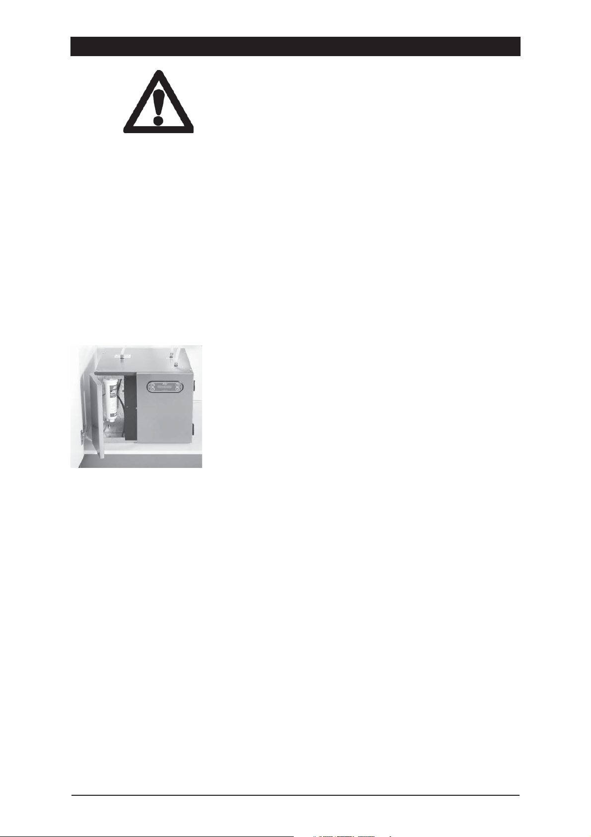
Zip Hydrotap undersink assembly.
The appliance must be placed in a
horizontal position, as shown above.
Note:
Always ensure the tubes are
shortened so that any excess is
removed and their route is the
most direct line between the tap
assembly and the HydroTap unit.
Do not allow the tubes to sag or
droop so water is trapped within
the hoses. Always maintain a
constant fall
Positioning of the tap assembly
must be within the following
parameters:
The height between the base of
the Hydrotap unit and the base
of the Tap assembly cannot be
greater than 900mm.
Lifting
Take care when lifting the Zip HydroTap undersink unit. Some units may
exceed safe lifting limits. Do not lift without assistance. The weights of the
units are given in the table under the heading “Installation Requirements”. Do
not lift the unit by the doors.
Airflow
The ambient temperatures this unit should operate within are 5ºC - 35ºC.
Proper air circulation must be provided. The system will operate satisfactorily
only if the recommended air gaps are provided, these are 65mm min rear
clearance and 50mm side clearance. An air vent is provided with each unit for
high usage applications, this must be installed in the top half of the cupboard
door as a matter of course. An accessory exhaust fan kit is available and
should be used to ensure adequate ventilation. Make sure that the ventilation
grilles of the undersink unit are not obstructed.
Included in the installation
pack are adhesive backed silicon buffers. If air vents are not installed in the
cupboards housing the HydroTap, the buffers must be placed on the inside
edge of the cupboard door to create a slight gap ensuring a minimum airflow.
Failure to do this may cause the HydroTap to overheat and operate inefficiently.
Minimum Pressure warning:
All BH and BCH models require a minimum cold water supply pressure of 2 bar
dynamic and a maximum of 7 bar.
Filter Control
The Zip HydroTap filter control is preset to 6000 Litres to provide trouble-free
flow and operation in most installations. Local water quality conditions may
require an alteration to this capacity. In areas where the water has a high
concentration of sediment, the preset litre capacity may be shortened to avoid
poor flow, taste or odour situations. In areas where the water quality is above
average, lengthening the preset capacity may be desirable, but not essential. If
any of these changes is needed, follow the instructions on page 11 or contact
your Zip Service Provider.
HydroTap Installation and Operating Instructions Page 3 of 20
Page 4
Read These Warnings continued
Frost Protection
If this appliance is located where the ambient air temperature could fall below 5ºC when the heater is not in use, do not
turn off the appliance electrically. This safeguard does not offer the same protection to the connecting pipework and
fittings.
Altitude
The Zip HydroTap is equipped with a self-calibrating program which caters for altitude adjustment.
Installation Environment Considerations
This unit is intended for indoor use only and should never be installed outdoors or exposed to the elements of nature.
This unit must not be positioned in an area that may be cleaned by a water jet. This unit must not be cleaned by a water
jet.
NOTE:
Zip HydroTaps are designed to operate within 1ºC to 2ºC of boiling point and at 5ºC to 10ºC for chilled drinking water.
Commercial models covered by these instructions
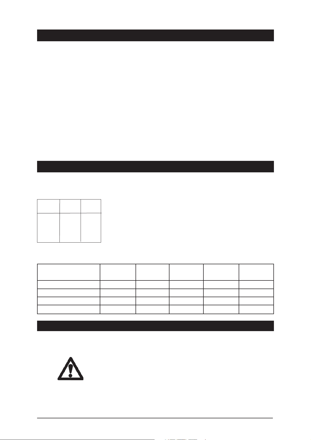
These Installation Instructions cover the 3-in-1 and 4-in-1HydroTap range. Use
the chart on the left to identify the model you are using:
Commercial Models:
BCH = Boiling / Chilled and Hot / Cold. (4-in-1)
BCH
Model
BCH100/125 - BCH160/125 337 (13.2) 473 (18.6) 440 (17.3) 28 (61.7) 35 (77.1)
BCH150/175 - BCH200/175 395 (15.5) 508 (20) 500 (19.6) 29.5 (65) 38 (83.7)
100
Cups of
Boiling Water
per Hour
Model Height
BH100F; BH160F 353 (13.8) 323 (12.7) 333 (13) 9.5 (20.9) 12 (26.4)
BH150F; BH200F 409 (16.1) 340 (13.3) 364 (14.3) 10.0 (22.0) 14.0 (30.8)
125
Glasses of
Chilled Water
per Hour
BH F = Boiling and Hot / Cold. (3-in-1)
Boiling Water Capacity:
100 = 100 cups in one hour** 150 = 150 cups in one hour**
** Capacity will be reduced by the volume of water used when operating the mixer tap.
Chilled Water Capacity: (BCH only)
125 = 125 glasses in one hour 175 = 175 glasses in one hour
Note: The Cup measurement = 167mls, the Glass measurement = 200mls.
mm (inch)
Depth
mm (inch)
Width
mm (inch)
Weight empty
kg’s lbs
Weight full
kg’s lbs
Installation Requirements
Before installing ensure that the following have been provided at the
installation site:
• Sufficient space in the cupboard to install the undersink unit in accordance
with these Installation Instructions. A table of dimensions is given above.
NOTE: Add 65mm to the Depth of the undersink unit to allow for Water
and Electrical connections.
• A water supply connection with isolating valve inside the cupboard
within reach of the 750 mm flexible connection and positioned so that
the connection point and the stop cock will not be obstructed when the
undersink unit is installed.
Page 4 of 20 HydroTap Installation and Operating Instructions
Page 5
Installation Requirements continued
• Power supply 220-240 Volt AC, for connection to the heater via a 13 amp fused spur.
• This switch must provide all-pole disconnection and a contact separation of at least 3mm installed in accordance
with wiring rules.
• Cold water supply with a minimum working pressure of 2 bar dynamic and a maximum working pressure of 7 bar
connected via an isolation valve. If pressure is likely to exceed 7 bar, install a 3.5 bar Pressure Limiting Valve.
• The fitting of an air flow vent cut into the top half of the cupboard door concealing the HydroTap requiring a cut size
of approximately 100mm circular, to provide adequate warm air displacement. In installations where high volume
draw-off will occur, the fitting of the accessory exhaust fan is essential.
Important: Do not proceed with the installation if these requirements are not met.
CAUTION: In order to avoid a hazard due to the inadvertent resetting of the thermal cut out, this appliance must not be
supplied through an external switching device, such as a timer, or connected to a circuit that is regularly switched on
and off by the utility
Special tools required
In addition to normal tools, the following will be required:
• 35mm diameter sheet metal hole punch for sink tops. (not supplied)
• 35mm diameter hole saw for timber bench tops. (not supplied)
• Nut runner tube spanner (supplied) for fixing tap assembly.
When installing a Font unit:
• 108mm diameter sheet metal or hole saw to suit surface being cut.
Installation procedure
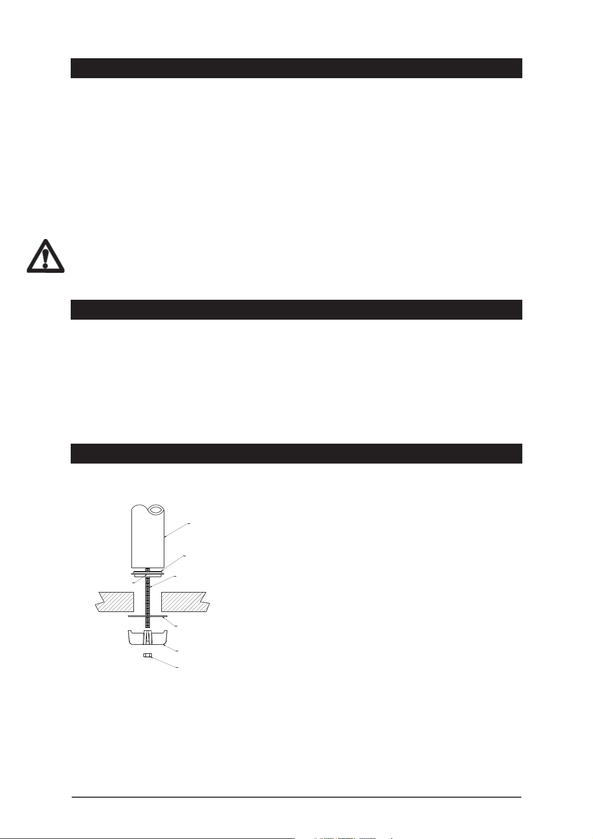
Step A - Installing the (Boiling / Chilled) HydroTap outlet
(see options P19)
1. Make sure that the tap location will allow the nozzle to drain into the sink.
Tap
Black
Plastic
Spacer
See para 3.
Note: A stainless steel washer
is supplied to go in between the
Spider Clamp and the underside
of the sink top. See location as
shown.
All-thread rod
Benchtop
S/S
Washer
Spider
Clamp
Fixing nut
2. Cut a 35mm hole in the bench / sink top.
3. Ensure the black plastic spacer remains in place as this is the moisture
seal against the bench / sink top. A light smearing of silicon sealant
on the underside of the spacer will ensure a watertight fit.
4. Pass all three hoses through the 35mm hole and carefully locate the Head
Assembly and black spacer on the bench / sink area.
5. From the underside of the bench / sink area install the S/S washer and
“Spider Clamp” by feeding each of the three tubes and electrical cable
evenly in between the legs of the “Spider Clamp”. Slide it up to meet the
“All Thread”, and pass the “All Thread” through the centre of the “Spider
Clamp”.
6. Hold the “All Thread” steady and fit the 6mm nut to the “All Thread” using
the tube spanner supplied in the kit. Check the Tap Head position before
securing it tightly against the bench / sink top.
NOTE 1: The tap assembly must not be positioned more than 900mm
above the HydroTap unit.
Failure to do this may result in poor water delivery.
NOTE 2: Under no circumstances should the Tap be twisted after the
installation is complete.
HydroTap Installation and Operating Instructions Page 5 of 20
Page 6
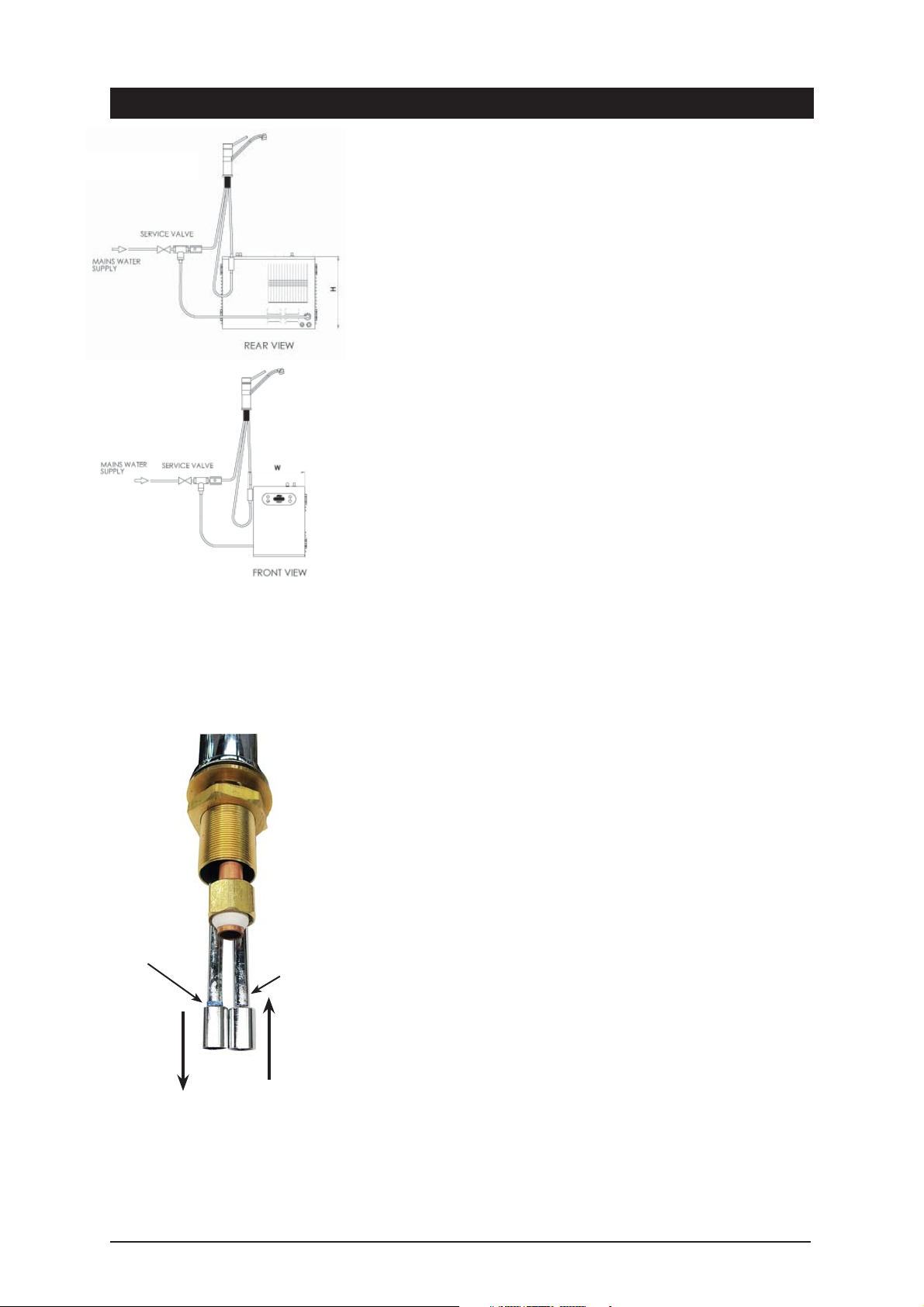
4-in-1 Mixer assembly
3-in-1 Mixer assembly
Installation procedure continued
Step B - Installing the (Hot / Cold) Mixer tap outlet
(see P19 options)
The approved vented tapware, as supplied must be used. It is advisable to
fit the tap to the sink before installing the undersink unit. Do not dismantle
the assembled tap body during installation. Mixer taps are factory tested and
sealed to provide optimum performance.
Before connection, it is recommended to flush water supply pipes thoroughly
to remove any silt or fines.
1. Make sure the tap location will allow the nozzle to drain into the sink. (P19)
2. Cut a 35mm hole in the bench / sink top.
3. Screw the 2 Braided hoses to the underside of the mixer tap, ensure that
each are firmly attached and in the correct colour or marking sequence.
See the diagram below for correct orientation.
4. Fasten the mixer tap body to the sink using the bolt & plate system
provided.
5. After the tap has been secured in place, screw the 1/2” tube (15) into the
remaining position on the underside of the mixer tap. (see diagram P18).
6. Connect the braided hose with a WHITE band to the incoming cold water
supply using the tee piece (23) and restrictaflow (20) (see diagram P18).
NOTE :
New hose sets supplied with the
unit should be used. Do not use
old hose sets.
Mixer tap
connections
Blue ring
on LHS
OUT
NOTE: The braided hose with the
blue ring markings must be fitted to
the tap outlet marked with blue. This
connection is on the Left Hand Side
when the tap is oriented as shown
above. Fit the white marked hose to
the RHS.
White
on RHS
IN
7. Connect the clear hose to the top of the venturi (1) and join the other end to
the check valve (11) and connection pipe (15) (see diagram P18).
8. Connect the braided hose with a BLUE band to the elbow (24) on the lower
end of the venturi (1) (see diagram P18).
Step C - Installing the undersink unit
SPECIAL NOTE: The HydroTap undersink units are heavy, take note of the
weights listed in the table on page 4. If you think you cannot lift the unit
safely, get help and avoid possible injury.
Before positioning the heater connect the braided water inlet hose (supplied)
from the cold water tee piece (see item 23 on P18) to the cold water inlet at
the rear of the unit.
Position the Zip HydroTap undersink unit as close as possible to directly
beneath the Zip HydroTap tap head.
The connection tubes supplied with the tap head assembly CANNOT be
lengthened.
Leave at least a 50 mm air-gap without obstruction on each side of the unit
and 65mm at the rear
The following instruction is CRITICAL:
Adjust both cupboard door hinges and attach the supplied rubber door buffers
to the doors to create a 4 mm air-gap between the doors and the cupboard.
This is the minimum ventilation requirement for low usage installations.
Proper air circulation must be provided for all Boiling and Chilled models. The
system will operate correctly only if the recommended air gaps are achieved
during installation. A ventilation hole measuring 100mm must be cut into the
top half of the cupboard door to accommodate the air vent provided. Make
sure that the undersink unit ventilation grilles are not obstructed in any way.
Cupboard ventilation for Boiling only models is recommended.
Page 6 of 20 HydroTap Installation and Operating Instructions
Page 7
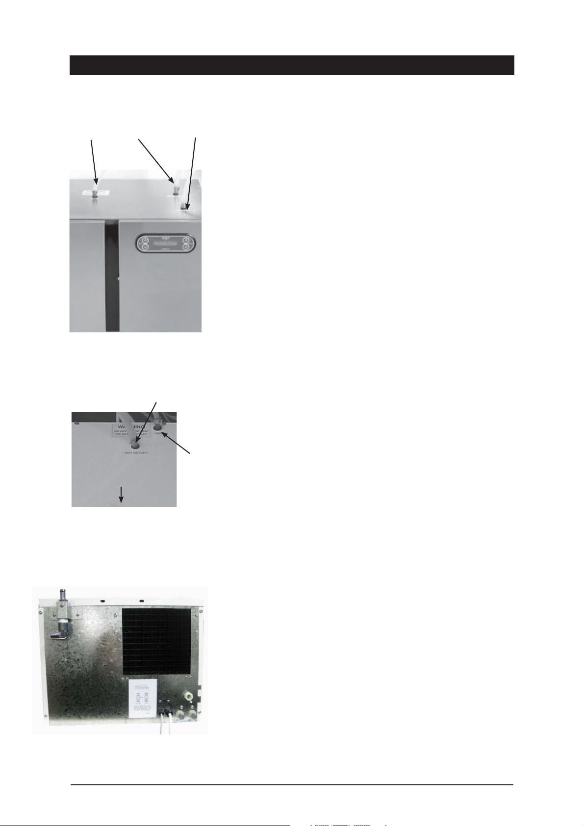
Vent line
Chilled line Hot line
4-in-1 HydroTap connections
Installation procedure
continued
Step D- Connecting the (Boiling / Chilled) HydroTap outlet
Note: Included in the installation pack are adhesive backed silicon buffers. If
air vents are not installed in the cupboards housing the HydroTap, the buffers
must be placed on the inside edge of the cupboard door to create a slight gap
ensuring a minimum airflow. Failure to do this may cause the HydroTap to
overheat and operate inefficiently.
Model BCH (4-in-1)
Measure and trim the blue tube and connect it to the chilled water outlet
located on the top front, right hand side of the undersink unit. Use spring
clamps provided to secure the hose.
Measure and trim the red marked tube and connect it to the hot water outlet
located on the top centre, right hand side of the undersink unit. Use spring
clamps provided to secure the hose.
Measure and trim the unmarked tube and connect it to the vent outlet located
on the top centre, left hand side the top of the undersink unit. Use spring
clamps provided to secure the hose.
NOTE: All tubes must have a continuous fall back to the undersink unit.
Connect the tap USB connector to the USB port on the undersink unit. Orient
the USB plug carefully and connect, do not force the plug. Once connected, fix
the cable to the wall, ensure it is away from any possible water splashes and
is off the floor.
Hot Outlet
Front
3-in-1 Hydrotap connections
Vent
NOTE: When trimming any silicon tubes trim to minimum length, do not loop
any excess or allow kinking of the tubes. When connecting, slide the tube over
the pipe at least 25mm. There are black plastic clamps provided on the boiling
and chilled hoses to choke the flow if required. Only choke the flow if it is
excessively strong.
Model BH (3-in-1)
Measure and trim the red marked tube and connect it to the hot water outlet
, on the top of the undersink unit. Use spring clamps provided to secure the
hose.
Measure and trim the unmarked tube and connect it to the vent outlet on the
top of the undersink unit. Use spring clamps provided to secure the hose.
NOTE: Both tubes must have a continuous fall back to the undersink unit.
Connect the tap USB connector to the USB port on the undersink unit. Orient
the USB plug carefully and connect, do not force the plug. Once connected, fix
the cable to the wall, ensure it is away from any possible water splashes and
is off the floor. Fasten the tap body to the sink using the bolt & plate system
provided.
Step E - Connecting an external filter.
(Not supplied as standard equipment).
To combat the build up of lime scale, a high performance external filter kit
may be ordered from your Zip service provider.
Rear panel with external filter fittings
HydroTap Installation and Operating Instructions Page 7 of 20
NOTE:- When fitted, the external filter will supply filtered water only for the Hot
tank. The internal filter will continue to supply filtered water for the cold tank.
- The external filter may require the inlet water pressure to be regulated to
lower than 6 bar. In this case a 3.5 bar Pressure Reduction Valve will be
required.
Page 8
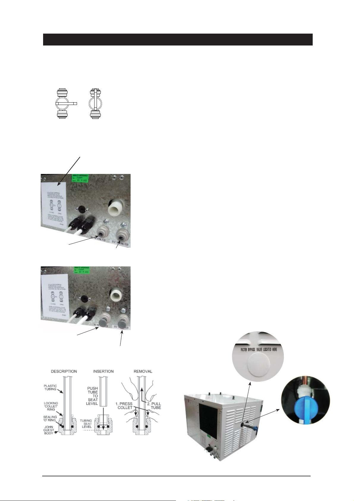
Installation procedure continued
TO ACCESS EXTERNAL
FILTER BYPASS VALVE,
REMOVE THE WHITE PLUG
LOCATED ON THE LEFT HAND
PANEL.
Fig.1
CLOSED
CLOSED
WHEN AN EXTERNAL FILTER
IS INSTALLED TO SUPPLY THE
HOT TANK, TURN THE VALVE
TO THE CLOSED POSITION.
Fig.2
Inlet from external filter
with plug removed
OPEN
OPEN
Outlet to external filter
with plug removed
- The rear of the unit is fitted with, 1/4” John Guest, inlet and outlet fittings,
specifically for the Zip high performance filter kit.
- These instructions must be read in conjunction with the filter fitting
instructions supplied with the high performance filter kit.
- The filter assembly must be located close to the appliance with sufficient
space for service access. Consult the instructions supplied with the filter kit.
To fit the external filter kit:
- Access the filter bypass valve, by removing the white plastic plug, located on
the Left hand side of the undersink unit (see Fig.5)
- Using a suitable set of pliers, close the filter bypass valve as instructed in
Figure 1.
- Remove the Inlet and Outlet plugs from the John Guest fittings as shown in
Figures 2 ; 3 and 4.
- After suitably mounting the filter assembly to an adjacent surface, measure
and trim the filter inlet and filter outlet tubes.
- Fit the tubes to their respective inlets and outlets, checking to ensure the flow
of water corresponds to the direction indicated by the arrow on the filter head
and by the instructions listed on the rear panel of the under sink unit.
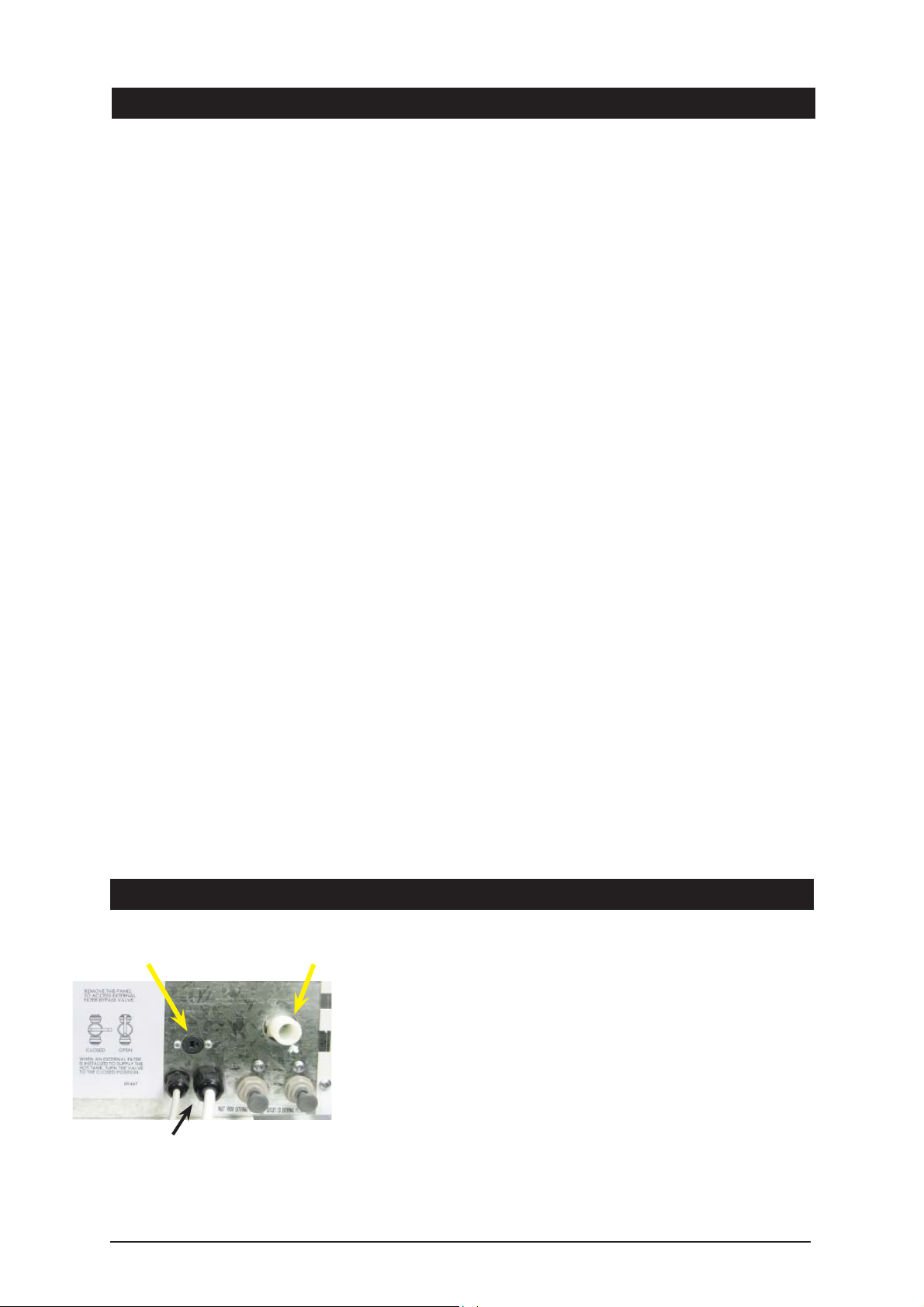
- Check the lower left hand John Guest fitting is the ‘Inlet from the external
filter’, and the right hand John Guest fitting is the ‘Outlet to the external filter’.
- Refit the white plastic plug and relocate the undersink unit, ensuring all air
gaps and clearances are maintained. (see P3 Airflow details).
- Activate the filter programme within the service mode.
After Testing and Commisioning (Step G)
Fig.3
Fig.4
- Set the external filter life - Max 3000 Litres
- Set external filter use (No need to flush the external filter)
- Check all connections for leaks
Inlet with plug
Outlet with plug
Fig.5
John Guest fittings: Insertion and removal
Accessing the filter bypass valve
Page 8 of 20 HydroTap Installation and Operating Instructions
Page 9
Installation procedure continued
Step F - Connecting the water supply
To prevent sediment from entering the Zip HydroTap at connection, flush water
through the supply line thoroughly before connection to the Zip HydroTap.
Open the access door and check that the filter is in place and secure. Connect
the water supply to the undersink unit using the attached flexible hose .Turn
on water and check for leaks. If no leaks are evident turn the power on.
Step G- Testing and commissioning
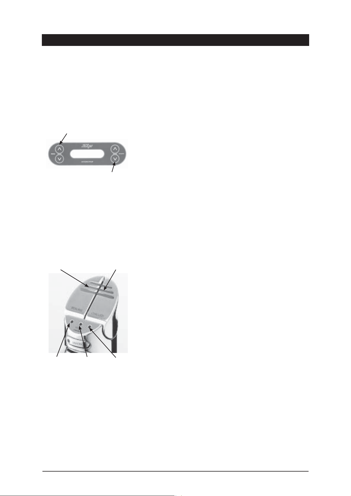
Filter Flush Mode The display screen will show which model you have.
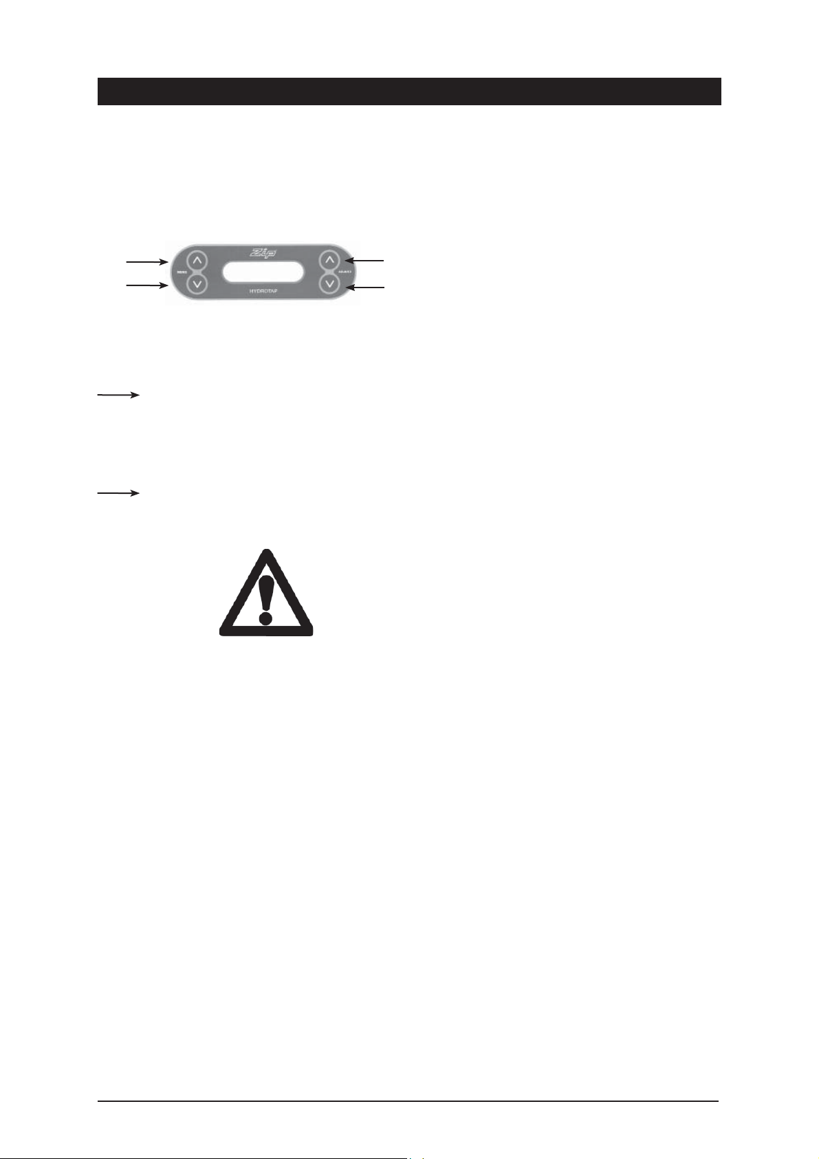
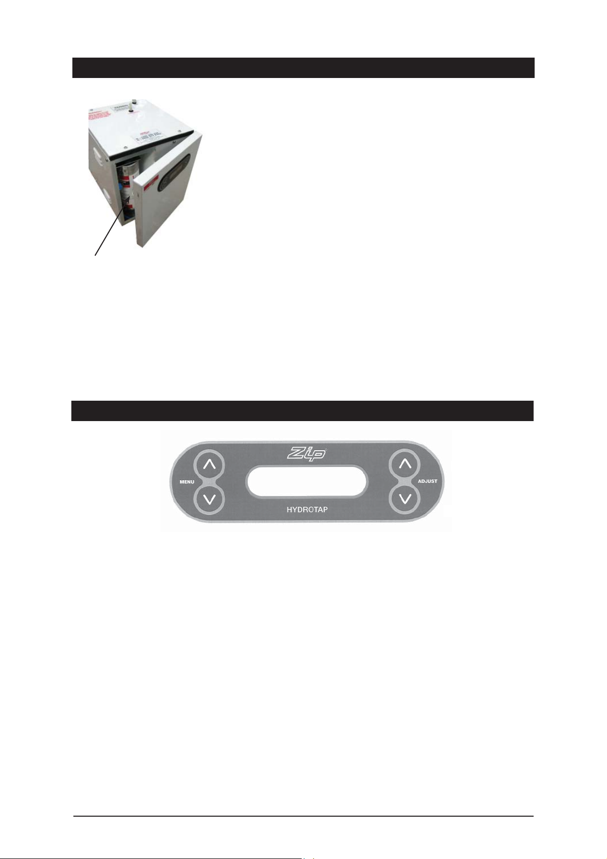
Use these buttons to
scroll through the menu
Have a bucket or similar container (not supplied) at the ready to hold a quantity
of water that is ejected while the Filter Flush Mode is in operation. Open the
filter access door on the front of the HydroTap and the filter cartridge will be
exposed. Located to the rear RHS of the cartridge is a fixed flush line, approx
600mm long and the flush line stop cock. Place the free end of the flush line
into the bucket or container (not supplied).
Use these buttons to
activate and de-activate
the program selected
Boiling Water Lever Chilled Water
Turn “ON” both water and electricity supplies and open the flush line stop
cock. The display will show Filter Flush Mode. To activate press adjust
<
Run at least 7.5 Ltrs of water through to activate the filter membrane.
Press the adjust < button again to stop the Filter Flush Mode. Turn OFF the
Filter Flush stop cock and re-locate the tube and stop cock in the filter
compartment. Turning OFF the Filter Flush Mode puts the HydroTap into
calibration mode. Press adjust <to start calibration. The element will now
cycle On and heat the water to 90ºC maintaining it at that temperature for a
short stabilization period.
Once stabilized, the element will cycle On, bring the water to boiling point and
hold it there for a short period.
The unit now carries out a self calibration function to ensure correct
temperatures are maintained. During this period the Red LED on the Tap Head
assembly flashes slowly until the calibration function is complete.
Once this step is complete (approx 5 minutes) the unit will default to normal
operation.
When starting, both Boiling and Chilled cycles activate simultaneously after
calibration has taken place, the descriptions below indicate what happens
during each cycle.
Boiling
The unit is now running in normal operating mode. The Red LED will flash until
usable temperature is reached.
Before using the HydroTap wait 5 minutes after this point to allow adequate
Red Light White Light Blue Light
fill time. The unit is now ready for use. Test water delivery from the tap and
check for appropriate temperatures. Use cable clips to tidy and secure wiring.
Chilled
When water and power is turned On, the Blue LED flashes slowly on the Tap
Head assembly. The compressor activates and water begins to fill the chiller
tank at the prescribed rate. When the water is chilled to 12ºC the Blue LED on
the Tap Head assembly stops flashing and stays illuminated. The compressor
continues to chill down to 5º when it will cycle Off.
Ensure that the clock matches your local time. If not refer to page 14 . If
Energy Saver Settings are required, the instructions for installing these are
described on page 14 “Setting the Energy Saver Timer”.
HydroTap Installation and Operating Instructions Page 9 of 20
Page 10
Installation procedure continued
Step H - Temperature set point adjustment
(Not normally required)
Temperature and Water level screen: (Service Default Screen)
To access this default screen, on the right hand side of the screen, press the ‘A’ adjust buttons together until the screen
changes to Service Mode, it will show the following:
Menu plus
Hot Temp Lvl
Cold Temp Lvl
Menu minus
NOTE: The temperatures shown are actual, not the set temperatures. To revert back to the Normal Operation screen,
press the adjust buttons together again until screen changes.
Press the Menu plus button, once, to enter the Hot Temperature Adjustment Screen:
Here you can adjust the Hot temperature set point by pressing the A adjust > or > buttons The Hot temperature set
point can be raised or lowered in 0.5ºC increments between 68º - 100ºC. Note: the Maximum setting of 100ºC is not
recommended for normal use. Do not raise temperature above 98.5ºC without consulting Zip first to discuss the service
issue.
Press the Menu minus button, once, to return to the service default screen:
Hot Temp Lvl
Cold Temp Lvl
A
A
To change the service default screen back to Normal Operation, press the adjust buttons together until the screen
changes back.
Warning:
Caution
normal operation of the unit.
must be observed when changing any settings within the Service Menu as changes may affect the
Page 10 of 20 HydroTap Installation and Operating Instructions
Page 11
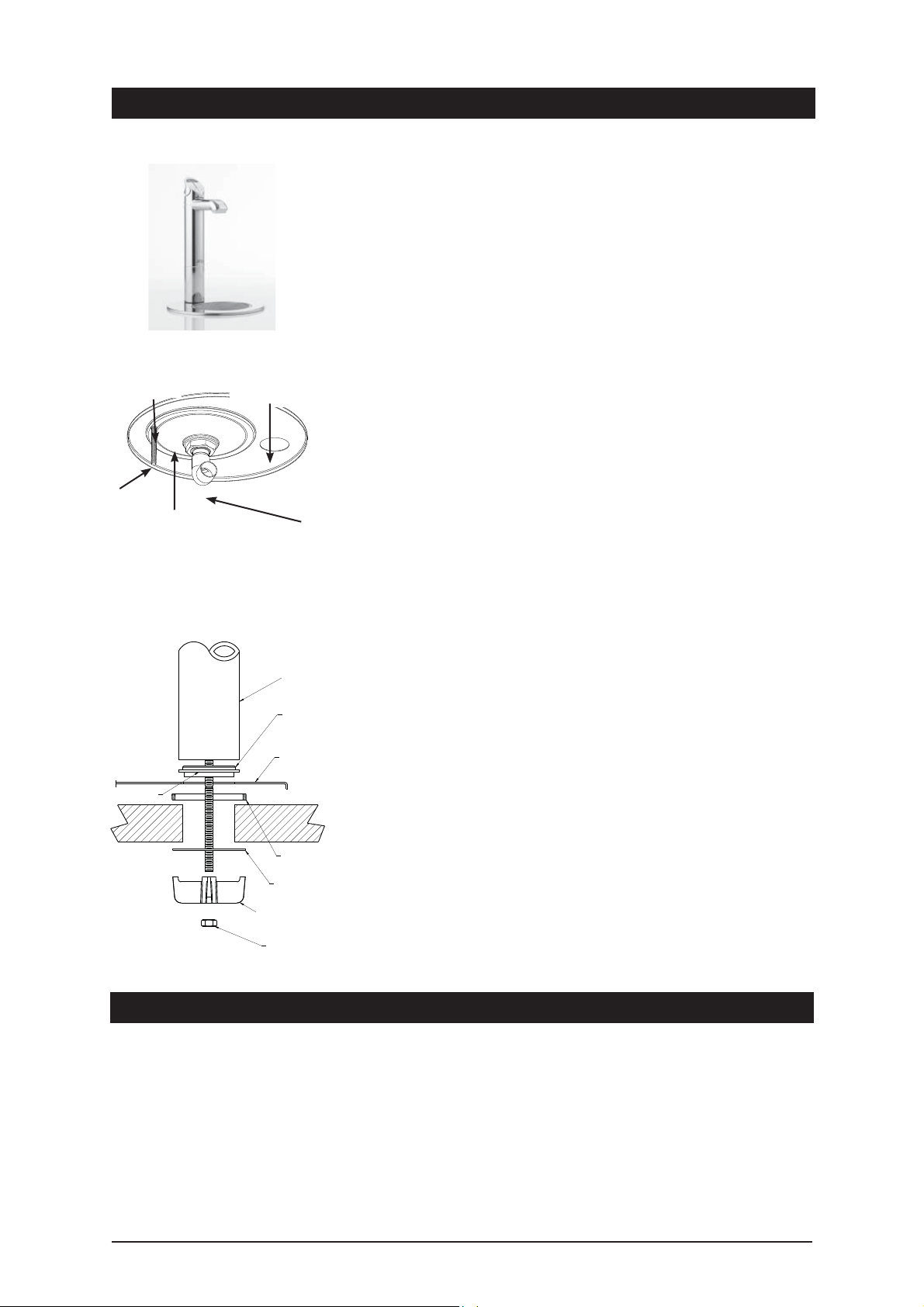
Fixing stud
Cut a 10mm
slot for stud
Hole required for Font
recess 108mm
View from underside
Tap assy
hole 35mm
Drain elbow
Font installation procedure
1. Position the Font template (provided) on the bench area. Ensure the
position you select is within the length of the supply tube and USB cable
fixed to the Tap Head Assembly. These cannot be extended.
2. Check again for correct positioning. The supply hoses must have constant
fall back to the tank assembly. Cut the holes as shown on the template.
3. Once holes are cut, locate the Font base in position, from the underside,
lightly tighten the securing rod with the nut and washer provided.
4. Apply a light smear of silicon sealant to the underside of the black base
ring, this will provide a water tight seal against the Font base when
clamped. * Ensure the plastic spacer is correctly located under the Font.
5. Now take the Tap Head Assembly. Feed the hoses and USB cable through
the Font base, then through the plastic spacer that sits under the font
base but on the bench top. This stops warping of the base plate. Ensure
the Tap spout is directly centred over the Font drain. Fit the “Spider
Clamp”, nut and washer onto the “All Thread”. Have all the supply tubes
and USB cable located evenly between the “Spider Clamp” legs. When
satisfied with the positioning, tighten the fixing nut with the Tube Spanner
provided in the kit.
6. Tighten the securing pin so the Font base is flush with the bench top.
NOTE: The fixing nut above the drain elbow can be loosened to correctly
position the direction of the elbow. Ensure when the re-positioning is
complete the nut is re-tightened to ensure a water tight seal.
See note 4.
All-thread rod
Tap
Black
Plastic
Spacer
Font
Benchtop
Spacer
Under Font
S/S Washer
Spider
Clamp
Fixing nut
7. Connect a drain hose (22mm ID) from the Font base outlet elbow to the
closest drain trap spigot available. If a spigot is not available use the snap
on spigot and worm drive clamps supplied in the kit. (Instructions and
diagrams are supplied in the kit ref:81496).
8. Ensure the positioning of the snap-on spigot is on the “sink” side of the
trap and not the “waste” side. Once positioned, a hole (13mm ID) will
need to be drilled to provide waste access to the drain line. The snap-on
unit will require suitable sealant to keep it water tight against the waste
pipe. Finish by fitting the worm drive clamps tightly on either side of the
spigot and fitting worm drive clamps to either end of the drain hose. The
drain hose from the Font must have constant fall
9. Connect the Tap head Assembly supply hoses and vent as per the
*
instructions contained in the installation procedure section of this
document.
NOTE: A stainless steel washer is supplied to go in between the Spider
Clamp and the underside of the benchtop. See location as shown.
Operating the Mixer tap
The Mixer tap is operated as a conventional ‘Flick Mixer’
Lifting the handle up will increase the flow rate and lowering the handle will
reduce the flow rate. Push the handle all the way down to turn the tap off.
When the handle is moved to the left, the temperature is increased and when
moved to the right the temperature is decreased. The final temperature will be
dependant on the temperature of the incoming cold water.
The spout may be swivelled, left or right, for convenience.
HydroTap Installation and Operating Instructions Page 11 of 20
Page 12
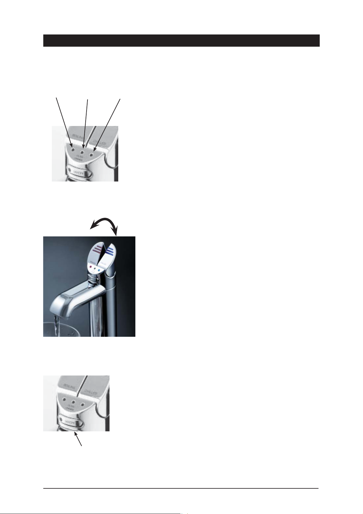
Boiling
Operating the HydroTap
Blue Chilled Water Light
On all the time:
This indicates that the temperature of the chilled water is within the usable
ChilledFilter Change
temperature range.
Flashing slowly :
This indicates that the chilled water is not at the right temperature. Wait
up to 20 minutes. When the chilled water is at the right temperature,
the light will stop flashing. Note: The Zip HydroTap is designed
to dispense chilled water in the temperature range 5°C to 10°C.
During heavy usage, the temperature can rise out of this range.
Red Boiling Water Light
On all the time: This indicates that the boiling water is ready.
Flashing slowly : This indicates that the boiling water is below usable
temperature.
Note: On the Boiling only models
the Chilled LED is blank.
Press or pull lever
Filter Change Light Off: This indicates the filter
is operating within its normal specified life span.
Filter Change Light Flashing slowly : The light will flash slowly when the
filter is due for replacement and the LCD will show “Filter Change”. Refer to
“Replacing the filter” section of this document.
Boiling Water Lever
Depressing the “Red” lever allows dispensing of Boiling water.
Pulling up the Red lever allows the tap to operate in a “no-touch” mode. Water
will flow from between 5 and 15 seconds (This is user adjustable). To reset,
return the handle to the “Off” position and repeat the step. The lever has to be
manually returned to the “Off” position.
Chilled Water Lever
Depressing the “Blue” lever allows dispensing of Chilled water.
Pulling up the Blue lever allows the tap to operate in a “no-touch” mode.
Water will flow from between 5 and 15 seconds (This is user adjustable). To
reset, return the handle to the “Off” position and repeat the step. The lever has
to be manually returned to the “Off” position.
Child Safety Lock (4 in 1)
The child safety lock can be activated to prevent boiling water flowing if the
hot lever is inadvertently activated.
To activate, first press the safety lock then depress the
Blue Chilled water lever for a period of approximately ten
seconds. The safety lock indicator light will now be illuminated.
To de-activate, first press the safety lock then depress the Blue Chilled water
lever for a period of approximately ten seconds. The safety lock indicator light
will now extinguish.
To operate when the lock is ON, depress both the Red lever and the safety
lock simultaneously.
Child Safety Lock (3 in 1 )
Child safety Lock
To activate the child safety lock , go to the LCD display, using menu< or
scroll to the Safety Lock display. To turn ON adjust < to turn OFF adjust
button. After about 10 seconds the screen will default to the selected mode.
<
<
When activated the LED on the safety lock will be illuminated. If de-activated
the LED will be OFF.
To operate when lock is ON, depress both the
Red lever and the safety lock simultaneously.
Page 12 of 20 HydroTap Installation and Operating Instructions
Page 13
External Filter Replacement
These instructions must be read in conjunction with the fi lter fi tting
instructions supplied with the high performance fi lter kit.
Depending on local water quality conditions and usage, the filter may require
changing anywhere from 1000 Litres to 3000 Litres. You may also need to
replace the filter if you notice unpleasant odours or tastes.
To change the pre-set filter life, scroll through the menu to “External Filter
>
Life”, press adjust
you sure”. Press adjust
To Change the external filter:
1. Scroll through the screen menu to “Filter Flush Off” this isolates the water
supply.
2. Relieve system pressure by lifting the Hot lever and allowing the water to
run until it shuts off automatically (15 secs.)
3. Remove and replace the spent external filter cartridge as described in the
filter kit instructions. Mop up any spills from the filter head.
4. Scroll through the menu to “External Filter Used ”, press adjust > to reset
the litres. Press adjust > and it asks “are you sure”. Press adjust > again
to lock in the command. After approx 10 seconds it will default to the
selected mode.
to reset litre counter. Press adjust > and it asks “are
>
again to lock in the command.
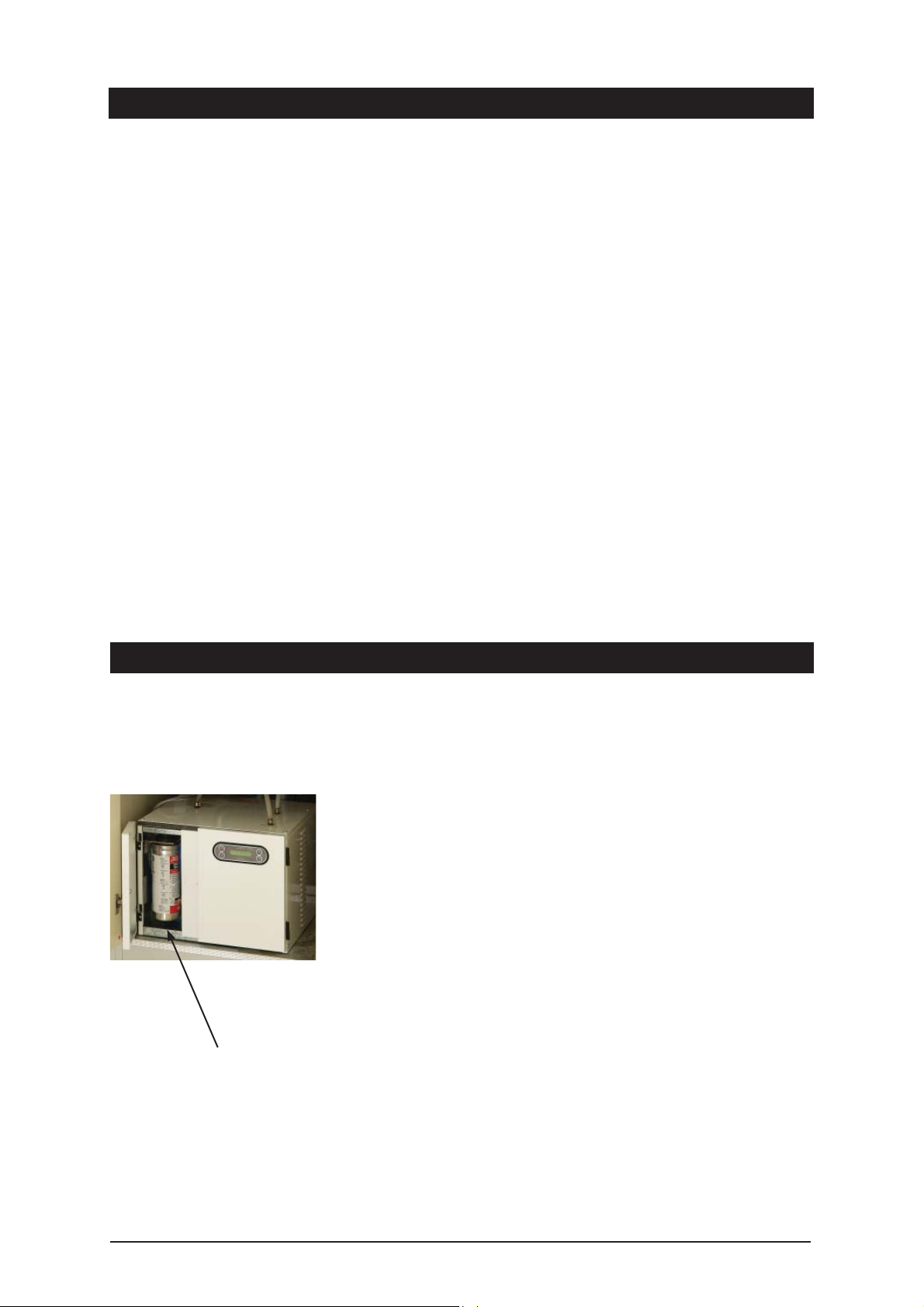
HydroTap filter location
Internal Filter Replacement
The Zip HydroTap notifies when filter replacement is due. The default setting
is 6000 Ltrs, but this can be set in increments of 1000Ltr from 1000Ltr to
10000Ltrs. When a filter change is due, the Change Filter light will flash white
once a minute and remain so until reset. A filter status light is located between
the Red and Blue Lights on the tap head assembly.
Depending on local water quality conditions and usage, the filter may require
changing anywhere from 1000 Ltrs to 10000 Ltrs. You may also need to
replace the filter if you notice unpleasant odours or tastes.
Some water may drip from the filter head (socket) during replacement. Keep a
bucket and towel handy to catch drips and mop up any spills.
To change the Filter:
1. Scroll through the screen menu to “Filter Flush Off” this isolates the water
supply.
2. Open the left door
3. Relieve system pressure via the filter flush stop cock, a quick open and
close will do.
4. Grasp filter cartridge and twist right to left one quarter turn until it stops.
5. Ease cartridge downwards to detach it from the filter head (socket).
6. Do not tilt the cartridge as dirty water may spill from it if tilted.
7. Unpack replacement cartridge and write today’s date where shown on the
label.
Page 13 of 20 HydroTap Installation and Operating Instructions
Page 14
Boiling unit - filter location
Internal Filter Replacement (Continued)
8. Avoid touching the filter “O” rings and filter opening as this may cause
bacterial contamination of the cartridge.
9. Align cartridge tabs with the slots on the under-side of the filter head.
10. Slide cartridge upward into head and rotate left to right until it stops.
11. Locate the filter flush hose situated behind the filter cartridge and run to a
container ready for flushing. Open the flush hose tap lever. On the control
>
panel press adjust
at least 7.5 Ltrs of water to run through to activate the filter and then press
adjust > to stop the flow.
12. Isolate the filter flush stop cock and re-fit behind the filter cartridge.
13. Wipe up any spills and dispose of spent filter cartridge and packaging
thoughtfully.
14. Scroll through the menu to “Litres Filtered”, press adjust > to reset litre
counter. Press adjust > and it asks “are you sure”. Press adjust > again
to lock in the command.
, this will start the water flushing the cartridge. Allow
Warning: If the Zip HydroTap is
switched off for a long period of
time (e.g. More than a weekend),
run water through the chilled water
outlet for at least 5 minutes before
consumption.
Mode Plus Button
Mode Minus Button
Note:
Mode buttons
change the
screen options
Adjust buttons
select the
screen options
Normal Operation Set Time
To change time, press either Mode < or Mode <button until Set Time is on the display screen.
Press <Adjust button to increase time or <Adjust button to decrease time. Time increases
or decreases in increments of one minute. Hold the Adjust buttons down for rapid increases or
decreases. The time will be displayed in 24Hr mode.
Set Day
Press either Mode
Press
15. Scroll through the menu to “Filter Used (Days)”, press adjust > to reset
the timer. Press adjust > and it asks “are you sure”. Press adjust > again
to lock in the command. After approx 10 seconds it will default to the
selected mode.
16. Close the door to secure the appliance.
Setting the Energy Saver Timer
<
or Mode <button until Set Day is displayed.
<
Adjust or <Adjust to select day.
Plus Adjust Button
Minus Adjust Button
Filter Life ( factory set at 6000 Ltrs )
Press either Mode <or Mode <button until Filter Life is displayed.
Press <Adjust button to increase Filter Life or <Adjust button to decrease Filter Life.
Filter Life increases in 1000 Ltr increments to a maximum of 10000 Ltrs.
Reset Litres Filtered
This function is to reset the Filter Change display after a filter has reached the end of its life (refer
to “Replace Filter Instructions” section of this document).
HydroTap Installation and Operating Instructions Page 14 of 20
Page 15
Setting the Energy Saver Timer
Press either Mode <or Mode <button until “Litres Filtered” is displayed.
Press <Adjust once and “Reset Counter” will be displayed, press <Adjust
button once and “Are You Sure” will be displayed.
Press <Adjust once and “Litres Filtered” will be reset to 0.
Activating Sleep Mode
This mode allows the HydroTap to go into Energy Saving mode. In this mode
the unit will go to “sleep” after a predetermined period of inactivity. Press
either Mode > or Mode > button until “Sleep Mode” is displayed.
Press > Adjust once to select
Option 1: Sleep to 65ºC after 2 hours of NO USE
Press > Adjust once to select
Option 2: Auto OFF after 2 hours of NO USE.
When the period of inactivity passes, the display will show “Sleep Mode”.
During the “Sleep Mode” the Red LED on top of the tap lever will flash slowly.
Sleep to OFF means the Boiling and Chilled circuits will be switched OFF
De-Activating Sleep Mode:
Momentarily operate the Hot lever on the HydroTap and then allow sufficient
time for the water to reach the set temperature
(continued)
Auxiliary fan
connection
Cold water
connection
Activating On / Off Mode
Press the Mode <or Mode <button until “Monday On” is displayed. To set
the time for the unit to turn on press <Adjust button until required time is
reached.
To set the time for the unit to turn Off press Mode <button once and “Monday
Off” will be displayed. Now press <Adjust until required time is reached.
If each individual day is to have an “On / Off” time, these steps need to be
repeated for each day and for each On / Off time.
Note:
The HydroTap may be temporarily activated during the On / Off Mode. By
operating the levers, the unit will go into normal operation and then remain in
an “ON” cycle, until the next “OFF” cycle.
Operating the Mixer tap will not De-Activate the sleep mode or the energy
saver On/Off timer mode.
Auxiliary Fan Attachment
The HydroTap is equipped with an auxiliary fan connection point on the rear
panel close to the cold water inlet / flex and plug area. The fan kit is available
as a spare part. The fan operates in parallel with the Condenser fan helping
to remove heat from the cupboard space. This fan should be purchased and
connected to the HydroTap if the airfow characteristics of the cupboard space
are inadequate for the effective removal of hot air, thereby adversely affecting
the operation of the HydroTap.
The fan can be installed so that it extracts air from, or forces air into the
cupboard space, whichever is the most effective for your installation.
Application of the fan is of paramount importance in situations where the
Electrical
connections
Page 15 of 20 HydroTap Installation and Operating Instructions
cupboard space reaches temperatures greater than 35ºC.
The exhaust fan kit must be fitted, when supplied with the appliance.
Note: The 150/175 and 200/175 models are supplied with the auxiliary fan kit.
Page 16

Boiling Water Isolation
The HydroTap is equipped with an additional safety mode that allows
protection against accidental operation by Infirm or disabled persons.
1. On the LCD scroll through the menu to Hot Isolation.
2. Press adjust > to activate.
3. Now go to the Tap Head assembly and press the Safety Lock (3) three
times rapidly, the LED’s will scroll from left to right (3) three times. This
operation confirms the activation.
4. This isolates the boiling tap only. The LCD shows isolation mode is active.
5. To temporarily de-actvate and dispense boiling water, press the Safety
Lock (3) three times rapidly, the LED’s will scroll from right to left (3)
three times. This operation confirms de-activation and will temporarily
de-activated. After 30 seconds of no use the unit will revert to normal
active mode.
6. If permanent de-activation is required, de-activate by scrolling through the
menu and selecting de-activate when Hot isolation Mode is displayed on
the screen.
7. The LCD will show Normal Operation.
Set the Boiling & Chilled water dispensing times
The ability to change the maximum dispensing time for both the Boiling and
Chilled water has been introduced. the default settings for the maximum
dispensing times is 15 secs. The ability to change both the Boiling and Chilled
dispensing times between 5 and 15 secs, in increments of 1 sec, is accessible
through the Menu screen on the LCD.
Scroll through the Menu until the Dispense Hot screen is displayed, then use
the adjust buttons to set the required dispensing time for the Boiling water.
Follow the same procedure to access the Dispense Cold (for Chilled water)
screens.
Cleaning
Do not use strong, corrosive, spray or abrasive cleaners. Clean with a soft
cloth or brush and mild soap and water.
Do not spray water over the tap as it may damage the low-voltage electronics.
Undersink units must never be located near, or cleaned with water jets.
End of life disposal
In order to help preserve our environment we ask that you dispose of this
product correctly. Please contact your local city council for collection centre
details
HydroTap Installation and Operating Instructions Page 16 of 20
Page 17

Trouble Shooting
Symptom Possible Cause Solution
No LED display, no tap head
lights or, no water when tap
levers are operated.
No water flow from HydroTap Water supply isolated. Check water supply is ON.
No water flow from mixer tap Faulty non return valve Check and Replace faulty non return valves (3 &11)
No hot water from mixer Hot tank empty - Excessive use Wait for tank to refill and reheat (see P16)
Slow water recovery after use Filter may require replacement. Check filter usage on LCD screen, if “filter change” is
No power. Check power supply.
Plug is not located in power socket. Ensure power plug is correctly fitted and switch is
turned ON.
Tap loom is not connected to
HydroTap unit.
Possible internal fault. Contact your authorised Service Provider. (P24)
Program in OFF cycle Check LCD for information.
Water supply not connected. Check to ensure plumbing connection is made.
Power supply not connected. Check power plug is correctly fitted and switch is
Tap loom is not connected to
HydroTap unit.
Possible internal fault. Contact your authorised Service Provider. (P24)
Program in OFF cycle. Check LCD for information.
Child safety lock is ON Deactivate Child safety lock. (see P16)
Faulty restrictaflow valve Clean and reset restrictaflow valve (item 20. P22)
Water supply not connected. Check plumbing connection & turn water ON
Faulty venturi check valve Replace faulty venturi check valve (item 3. P22)
Check loom connection.
turned ON.
Check for loom connection
displayed follow instructions on page 17.
Water not hot Unit is in Sleep Mode. Momentarily operate the HydroTap Hot lever and wait
for the Red LED to stop flashing. (see P19)
Unit has just come out of OFF cycle. Wait for Red LED to stop flashing.
Possible internal fault. Contact your authorised Service Provider. (P24)
Water not chilled Excessive use, unit refilling or
chilling down to temperature.
Possible internal fault. Contact your authorised Service Provider. (P24)
Alternating display messages More than one fault identified at the
same time
Hot tank overflowing Faulty venturi check valve Check & Replace faulty non return valves (3 & 11)
Mixer tap operation reversed Braided hoses incorrectly fitted Check position of Blue and White connections (P6)
Wait for Blue LED to stop flashing. (see P16)
Record the number and type of faults
Contact your authorised Service Provider. (P24)
Page 17 of 20 HydroTap Installation and Operating Instructions
Page 18
CONNECTED ON
HOLE WITH RED
MARK UNDER TAP
CONNECT TO
HOLE WITH NO
COLOURED
MARKING
UNDER TAP
BRAIDED HOSE
WITH WHITE
TO
28
2ND TAP
RING
87570
15
14
13
12
11
10
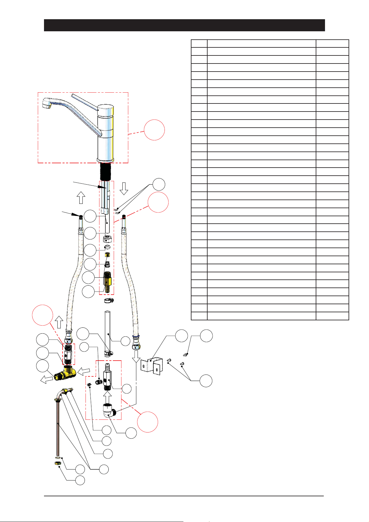
Exploded view of Mixer assembly and spare parts
ITEM DESCRIPTION PART NO.
1 Venturi - Main body
2 Venturi - Top fitting
3 Check Valve 8mm Neoperl
4 Olive #2, 5/16 Compression
5 Nut #1, 5/16 Compression
6 Brazed- 2nd Hot Outlet Tube 3 Litre
Bush - 2nd Hot Outlet Tube
Tube - 2nd Hot Outlet Tube 3 Litre tank
6 Brazed- 2nd Hot Outlet Tube 5 Litre
Bush - 2nd Hot Outlet Tube
CONNECTED
ON HOLE
WITH BLUE
MARK UNDER
TAP
BRAIDED HOSE
WITH BLUE
25
16
26
RING
Tube - 2nd Hot Outlet Tube 5 Litre tank
7 O-Ring BS014 Silicone
8 Nut - 1/2” Brass x 26tpi
9 Hose - Clear PVC reinforced 1meter long
10 Fitting - 15NRV + Barbed 1/2” BSP
11 Check Valve 15mm Neoperl
12 Sleeve
13 Olive - 1/2” Nylon
14 Nut - 1/2” BSP Kinko Brass - Plated
15 Brazed 1/2” dia Tube to Fitting
16 O-Ring Nitrile (2 off)
17 Bracket - Venturi Mounting
18 Screw - M4x10 Taptite Phillips Pan Hd (2 off)
19 Screw - M4x 6 Slot Pan Hd (1 off)
20 Restrictaflow - drilled to 2.5mm i.d.
21 Clamp - 13mm Hose
22 Tee - 1/2” BSP Female Brass
23 Nipple - 1/2” tapered No. 27
24 Elbow - 1/2” BSP M/F Brass
KIT LIST
25 Hydrotap 4in1/3in1 Tapware Kit 92258
26 Barbed Fitting Assembly Kit 99186
27 Venturi Assembly Kit 99187
28 RestrictaFlow for Venturi Models Kit 99188
20
21
9
17 19
2
22
23
AMBIENT
WATER
FROM
MAINS SUPPLY
18
TO HYDROTAP
UNIT USE 87444
BRAIDED HOSE
BOILING
WATER
FROM
HYDROTAP
3
4
5
1
24
27
FOR ITEM 20 USE AN 81841 RESTRICT-A-FLOW
AND DRILL ø2.5mm HOLE INSIDE.
87706
- VENTURI ASSEMBLY HTAP 4-IN-1
SUITABLE TO 3Li HOT TANK
(EXCLUDES TAP)
87707
- VENTURI ASSEMBLY HTAP 4-IN-1
SUITABLE TO 5Li HOT TANK
(EXCLUDES TAP)
67
8
Page 18 of 20 HydroTap Installation and Operating Instructions
FILENAME: 87706-VENTURI-COMPLETE-SET-UP.DRW
Page 19
3-in-1 Installation Options
NOTE:
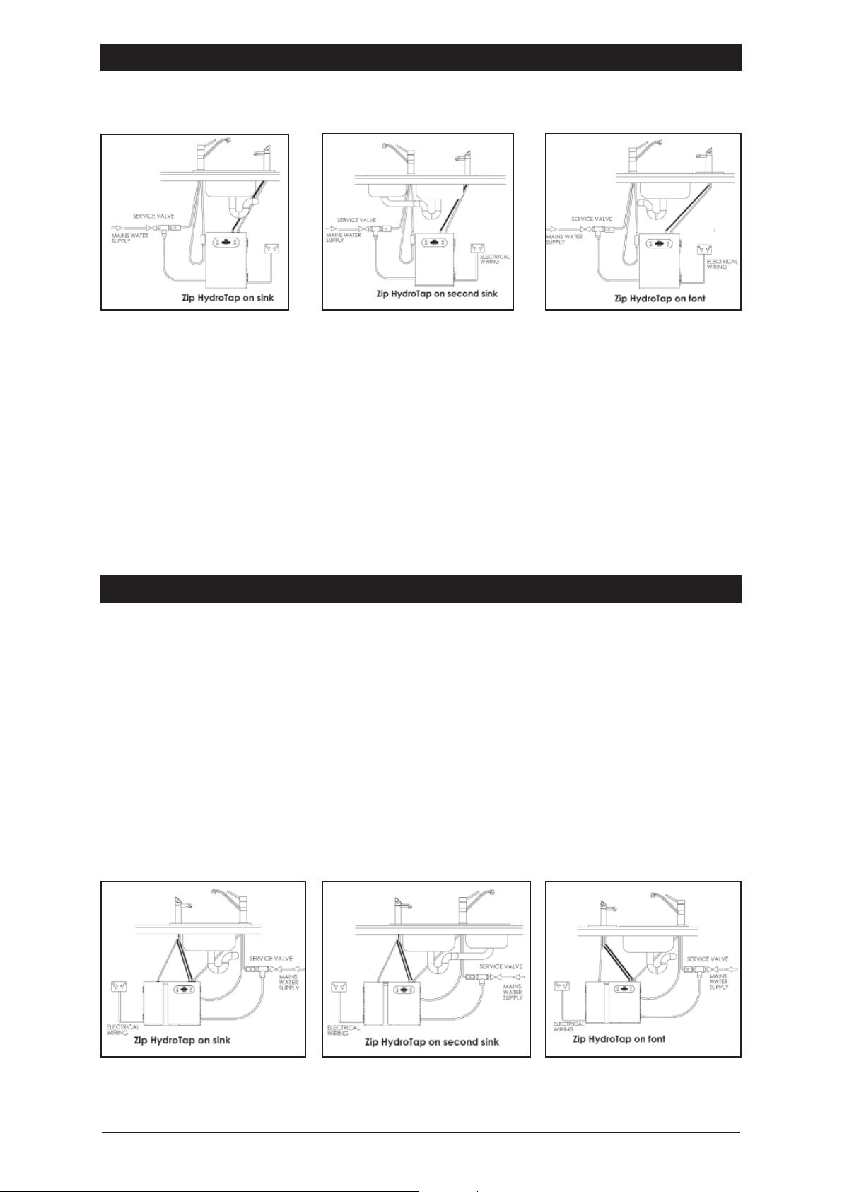
The Venturi connection for the 3-in-1Mixer tap is located on the Left Hand side
of the undersink unit.
The Mixer tap may be fitted (as shown above) to supply Cold or Hot water to
one or two sinks.
The HydroTap may be fitted to supply filtered Boiling water to any one sink or
may be fitted with a Font kit, when a sink is not available. The Font must be
connected to a suitable drain.
4-in-1 Installation options
NOTE:
The Venturi connection for the 4-in-1Mixer tap is located at the back of the
undersink unit. Connections to the Venturi should be made prior to fitting the
undersink unit in place
The Mixer tap may be fitted (as shown below) to supply Cold or Hot water to
one or two sinks.
The HydroTap may be fitted to supply filtered Boiling or Chilled water to any
one sink or may be fitted with a Font kit, when a sink is not available. The Font
must be connected to a suitable drain.
HydroTap Installation and Operating Instructions Page 19 of 20
Page 20
Warranty
Certain warranties may be implied by law into your contract with Zip. The warranty provided below is additional to these
implied warranties and nothing set out below shall limit your statutory rights or rights at law.
Zip Heaters (UK) Ltd warrants that, should any part fail within 12 calendar months of installation, that part will be
repaired or replaced free of charge by Zip or its Distributor or Service Provider, except as set out below, provided
the appliance is installed and used strictly in accordance with the instructions supplied, and that failure is not due
to accident, misuse, abuse, unsuitable water conditions, or to any alteration, modification or repair by any party not
expressly nominated by Zip.
No costs are payable by the customer other than any mileage or travelling-time charges incurred by a Zip Service
Provider or the cost of removal, cartage and re-installation of any component of the appliance if it needs to be returned
for repair to Zip or its Distributor.
This warranty does not cover damage resulting from non-operation of the appliance, the use of non authorised parts or
consequential damage to any other goods, furnishings or property.
No warranty applies to the life of any filtration cartridge installed with the appliance as cartridge life may vary according
to water quality and the rate of water consumption.
Zip does not exclude, restrict or modify any liability that cannot be excluded, restricted or modified or which cannot,
except to a limited extent, be excluded, restricted or modified as between the owner or user and Zip under the laws
applicable.
Furthermore, this warranty does not displace any statutory warranty, but, to the extent to which Zip is entitled to do
so, the liability of Zip under any statutory warranty will be limited at Zip’s option to the replacement of the appliance or
supply of equivalent appliance, the payment of the cost of replacing the appliance or acquiring an equivalent appliance,
or the payment of the cost of having the appliance repaired or the repair of the appliance.
Registering Your Purchase
Registering your Zip installation on the Zip website may help to establish date of installation should it become necessary
to service the appliance under terms of the Zip warranty. To register your installation go to www.zipheaters.co.uk and
look under the heading “Warranty”.
As Zip policy is one of continuous product improvement, changes to specifications may be made without prior notice.
Images in this booklet have been modified and may not be true representations of the finished goods.
Head Office
Zip Heaters (UK) Ltd
14 Bertie Ward Way
Dereham
Norfolk NR19 1TE
Website: www.zipheaters.co.uk
[email protected]
Telephone: 0845 602 4533
Facsimile: 01362 692 448.
The standard cup referred to in this publication is 167 ml (6 fl oz).
The standard glass is 200 ml (7 fl oz).
The terms “Zip” and “HydroTap” are registered trade marks of Zip Heaters (Aust) Pty Ltd.
Zip products described in this publication are manufactured under one or more of the following
patents: AU675601, AU637412, AU635979, GB0422305, GB2065848, US4354049, US5103859,
and US5099825. Other patents are in force and patent applications are pending.
Page 20 of 20 HydroTap Installation and Operating Instructions - 87737UK - June 2012 v1.04
 Loading...