

Page 1
TROUBLESHOOTING
TROUBLE
1. Fan will not start - Check wiring connections to fan.
- Check fuses and circuit breakers.
- Check wiring connections in switch housing.
CAUTION: Turn power off for last two items.
2. Fan sounds noisy - Check to make sure that all screws in motor housing are snug.
- Check to make sure that blade bracket screws are tight.
- Check to make sure that marrettes in switch housing
are not rattling against wall of switch housing.
- If fan has a light kit make sure switch housing
screws and set screws are tight.
- Some fan motors are sensitive to signals from solid
state variable controls. If solid state controller is
used, change to an alternative control. (See a
representative for a list of available controls.)
- Allow a 24 hour break in period to eliminate most noises.
3. Fan wobbles - Check that all blades are screwed firmly into blade brackets.
or shakes
excessively.
- Check that blade brackets are secured firmly to motor.
- Check distance from tip of blades to ceiling.
- Check
distance between blade tip to blade tip. All
measurements should be equal. Loosen blade
screws and position blade until even then re-tighten.
- Check that the downrod hemisphere notch is engaged in canopy.
- Check to make sure that jam screws in downrod are tightened.
- Make sure canopy and mounting bracket are
tightened securely to wooden joist.
- Make sure warpage has not occurred in wooden
blades. If so, contact the customer service
department for replacement parts.
SUGGESTIONS
INN
I
A
STT
LLLAATT
S
L
A
INSTRUCTIONS PERTAINING TO RISK OF FIRE OR INJURY TO PERSONS
I
O
I
O
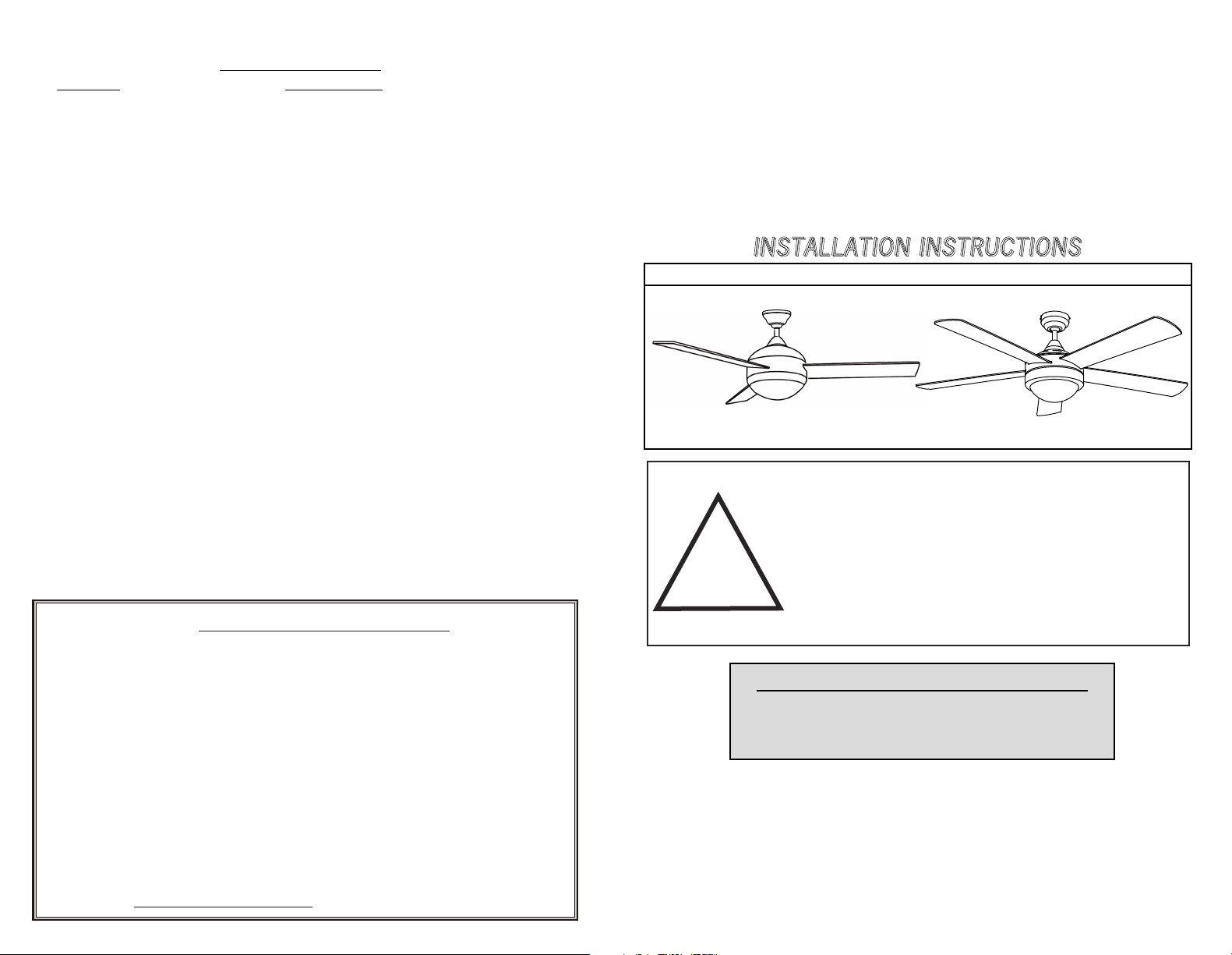
DUAL MOUNT SERIES
STTRRUUCC
NNIINNS
READ ALL INSTRUCTIONS
N
TTIIOON
S
S
IMPORTANT SAFETY
INSTRUCTIONS
5 YEAR LIMITED WARRANTY
“Thank you” for purchasing our product. It is our policy to furnish you with high quality
products at a fair price. With proper installation your fan should provide you with years of
money saving comfort.
This fan is guaranteed to be free from defects in workmanship and Material for a period
of five (5) years from date of purchase. Within the first (1) year from date of purchase any
defective product should be returned to your RETAIL OUTLET along with proof of purchase.
For the balance of the warranty, four (4) years, the MOTOR WINDINGS ONLY shall be free
of defects. We will correct such defects or replace the motor assembly at our option if the
product is returned, FREIGHT PREPAID, to us. The returned fan must be accompanied by
your proof of purchase and a cheque for $20.00 for handling and labour charges. All costs of
removing and re-installing the product are YOUR RESPONSIBILITY damage to any part as
such by accident, misuse, improper installation or by affixing any accessories IS NOT covered
by this warranty. As a result of varying climatic conditions in our area this warranty does not
cover any changes in finishes, including rusting, pitting, corroding, tarnishing or peeling.
WARRANTY VOID: In cases of alteration, abuse, installation not in accordance with
.rekcitS AS C eht fo LAVOMER ro snoitcurtsni
11/16
!
SAVE THESE INSTRUCTIONS
INSTALLATION AND WIRING TO BE IN ACCORDANCE WITH CEC,
NEC, LOCAL ELECTRICAL CODES and ANSI/NFPA 70.
Consult a qualified electrician if you are not familiar with wiring.
TOOLS AND MATERIALS REQUIRED
- Philips Screw Driver
- Blade Screw Driver
- Wiring supplies as required by electrical code.
- Step Ladder
- Wire Cutters
Page 2
SAFETY PRECAUTIONS
1. Turn off power at main electrical service box before starting installation.
2. Electrical connections must comply with local code ordinances, national
3. Make sure the installation site you choose allows the fan blades to rotate
4. When mounting the fan on a ceiling outlet box, Use an approved (CSA for
5. WARNING: To reduce the risk of fire, electric shock, or personal injury,
6.Total Fan Weight For Reference: 48"approximate 8.0 kgs(17.63lbs).
52"approximate 9.0 kgs(19.84lbs).
electrical codes, CEC, NEC and ANSI/NFPA 70.
freely without any obstructions.
Canada and UL for U.S.) ceiling fan box marked "FOR FAN SUPPORT".
Ensure the outlet box is securely installed in place such that it is able to
support at least the fan weight.
mount fan only to an outlet box marked acceptable for fan support and use
mounting screws provided with the outlet box. Most outlet boxes commonly
used for the support of lighting fixtures are not acceptable for fan support
and may need to be replaced. Consult a qualified electrician if in doubt.
.
77.
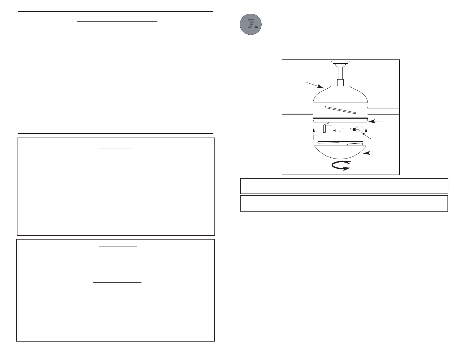
LIGHT ASSEMBLY
- Install proper wattage and type of bulb dentified on light housing or shade.
- Place glass onto the fan and turn to secure.
WARNING : BE SURE TO TURN OFF POWER BEFORE INSTALLING
Motor
Light Kit
WARNING
educe the
- To r
remote control for optional remote control adaptability.
-
WARNING: TO REDUCE THE RISK OF FIRE, ELECTRIC SHOCK, OR PERSONAL
risk of fir e or
electrical
shock,
INJURY, MOUNT TO OUTLET BOX MARKED ACCEPTABLE FOR FAN SUPPORT
AND USE MOUNTING SCREWS PROVIDED WITH THE OUTLET BOX.
- Mount
- DO
with the lowest moving parts at least 2.10 Meters (7 Feet) above
floor or
be
must
grade level.
NOT operate reversing switch while fan blades are in motion. Fan
turned off and rotating blades stopped, reverse chain pulled, the speed
pulled again to start in the opposite direction.
chain
- WARNING: TO REDUCE THE RISK OF INJURY TO PERSONS, ENSURE THE FAN
LOWER COVER IS SECURELY ATTACHED ON THE FAN UPPER COVER BEFORE USE.
INSTRUCTIONS
The slide switch is for forward/reverse rotation.
In cold weather: Set to reverse rotation (clockwise). Airflow will be directed upward,
circulating warm air..
In warm weather: Set to forward rotation (counter-clockwise). Airflow will be directed
downward, circulating cold air.
.
REMOTE CONTROL
Install DC1.5V/AAA*2pcs battery (not included).Operation buttons on the remote:
HI : Turn
MED : Turn on the fan at medium speed
LOW : Turn on the fan at low speed
OFF : Turn off the ceiling fan
LIGHT ON/OFF: Press and release immediately to turn on or off the light.
DIMMER- Press and hold to dim or brighten lights to the desired level
The light has a memory function so the light will stay at the same brightness as the last time it was turned off.
on the fan at high speed
and release. (Incandescent light bulbs or dimmable LED bulb only).
*Hold down to increase or decrease the light.
Pg. #2
Bulb
Glass
Fig.9
WARNING: Ensure that all connections, set screws and screws are securely
tightened
before the next step.
To clean the fixture, turn off the power, wait for it to cool, and wipe the fixture
with a clean, soft cloth.
Pg. #11
Page 3
44.
ELECTRICAL HOOK-UP
.
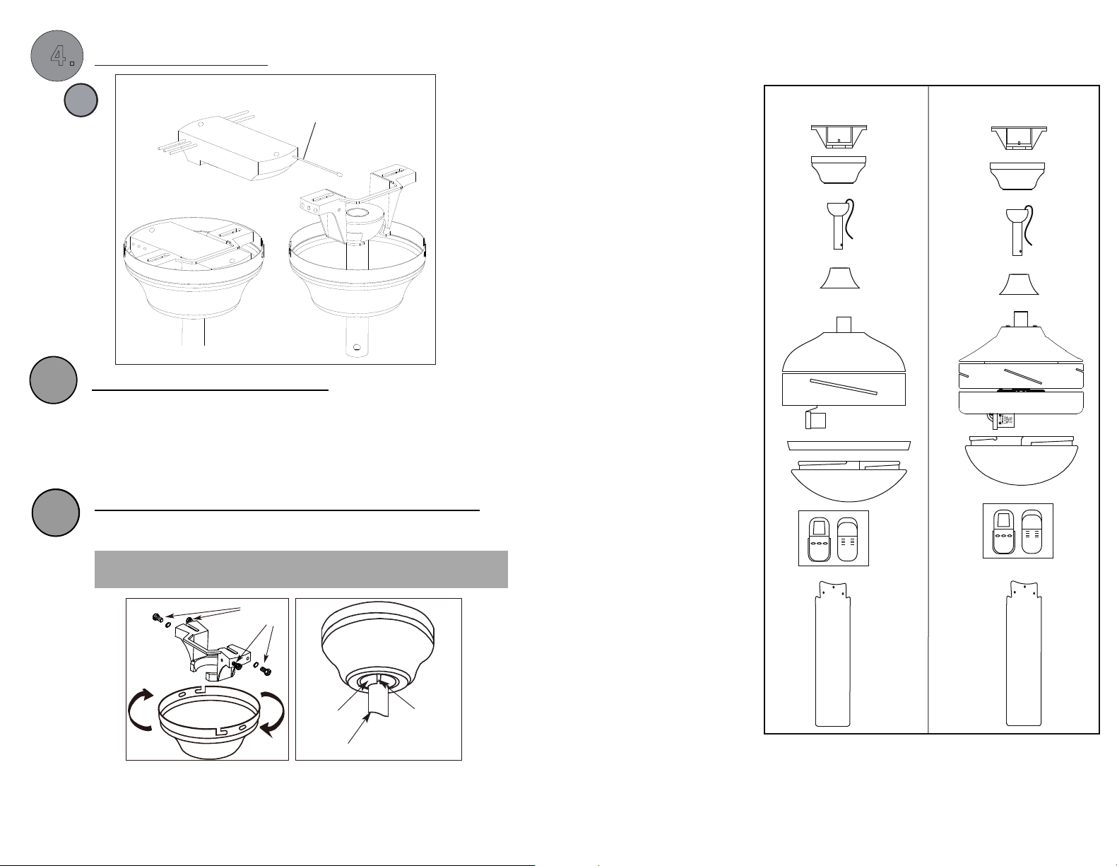
ASSEMBLY DRAWING
5.
C
VIEW AFTER INSTALLATION
ANTENNA
(Leave unconnected
and do not cut)
Fig.7b
MOUNTING FAN ASSEMBLY
- Place two screws and washers on mounting plate (marked B on diagram)
which correspond with slots in canopy. Screw in two turns.
- Position canopy to mounting plate aligning slots to screws (marked B on
diagram) then turn to lock.
- Position and tighten the two screws and washers (marked A on diagram)
then tighten the two screws (marked B on diagram).
A. Mounting Bracket
B. Canopy
C. Downrod Assembly
D. Yoke Cover
E. Fan Motor Assembly
F. Motor Cover
G. Glass
H. Remote Control
I. Fan Blade
For model Calibre
A.
B.
C.
D.
E.
F .
G.
For model Preston or Cove
or Corbo
A.
B.
C.
D.
E.
G.
6.
6.
ENGAGE HEMISPHERE (Downrod Mount Only)
- Carefully rotate fan assembly until groove in hemisphere locks over tab of
NOTE: When installing fan on sloped ceiling, make sure tab on hanger bracket
faces towards the top of the slope. Depending on the slope, a longer
downrod may be required to prevent fan blades from hitting the ceiling.
canopy assembly.
WARNING: Failure to seat tab in groove could cause damage to
electrical wires and possible shock or fire hazard.
(B)
(A)
Washers
(A)
Fig.8a
(B)
Hemisphere
Downrod
Groove
Fig.8b
Pg. #10
H.
I.
Fig.1a
H.
I.
Fig.1b
Pg. #3
Page 4
ATTACH THE FAN BLADES
.
11.
b2 dna a2.giF :erbilaC ledo m roF
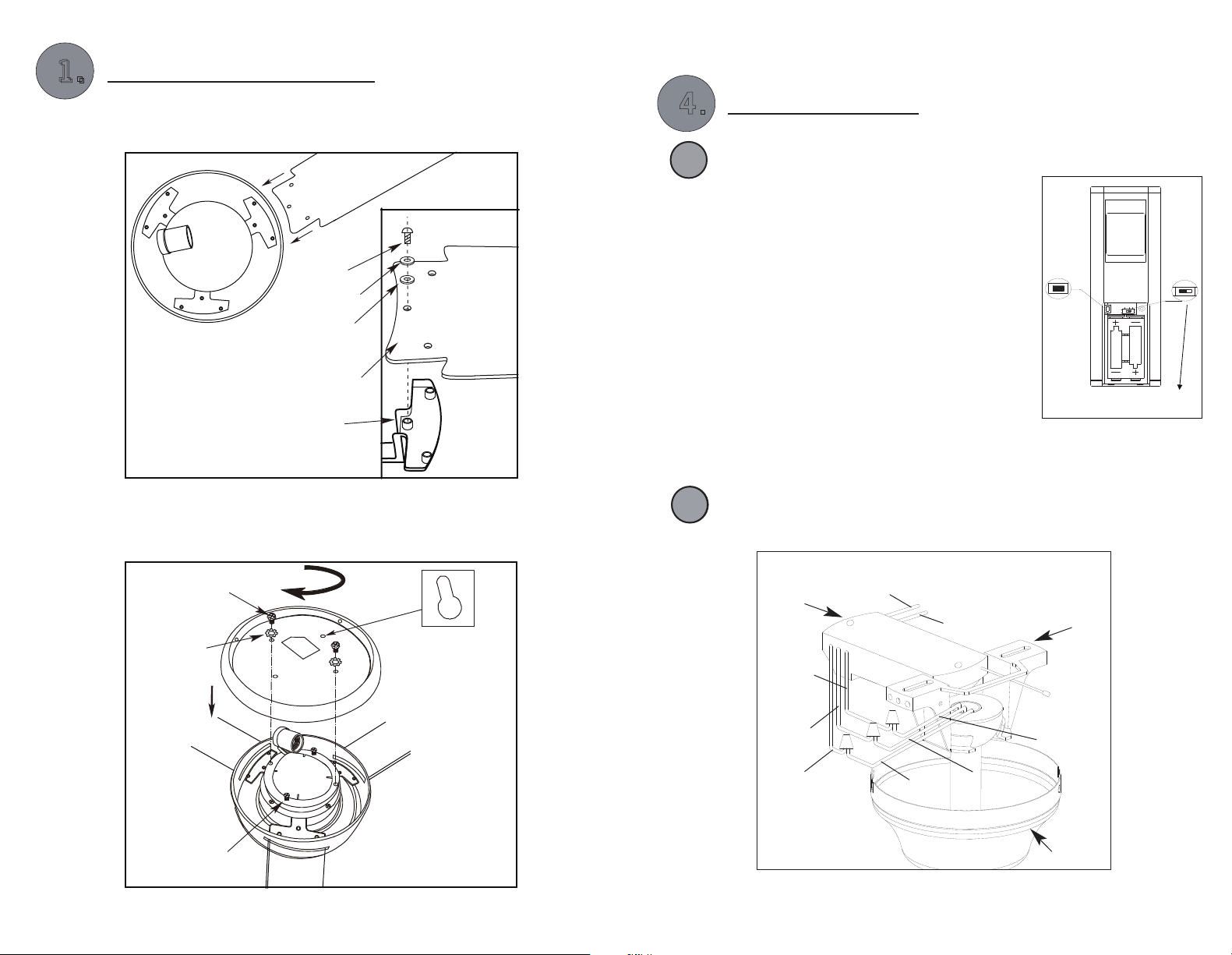
- Attach the blades to the fan motor assembly using the screws and flat
washers.
Blade
Bracket Screw
Metal Washer
Fibre Washer
Blade
Blade Bracket
Fig.2a
4..
4
ELECTRICAL HOOK-UP
LEARNING PROCESS
B
-. After installation of the fan, power on the fan. Open battery cover and
install battery, DC1.5V/ AAA*2 pcs that are not
included. Use a ball pen to press and hold the
“LEARN” key for 1-3 seconds.
-. FAN will be turned “OFF” and then “ON” at
medium speed. This indicates the learning
process is completed.
-. Please GO through this learning process
within 30 seconds after power on.
-. If just replace batteries, no need to re-learn.
-. Please note that the transmitter can learn in
multiple receiver while doing learning process.
-. Please make sure NOT to turn on other fans
while learning.
Fig.6
LEARN
LIGHT FUNCTION SELECT SWITCH
-. If a fluorescent lamp is used, slide the function
switch to "O" position.
-. If a regular incandescent lamp is used, slide switch to the “DIM” position.
AAA DC 1 . 5 V
AAA DC 1 . 5 V
LIGHT FUNCTION
SELECT SWITCH
O/ DIM
- Mount the motor cover to the fan motor assembly, aligning screws in
motor fan assembly with the key slots on the motor cover. Turn cover
to lock in place and tighten screws.
Light Kit
Screw
star
washer
Fig.2b
Pg. #4
- Push all connected wires up into ceiling box.
C
Position the receiver into the canopy as shown direction.
Fig.7a
Reciever
BLUE
WHITE
BLACK
BLACK
BLACK
SUPPLY
CIRCUIT
120V
WHITE
WHITE
Fan
Pg. #9
Mounting
Plate
ANTENNA
BLUE
Canopy
Page 5
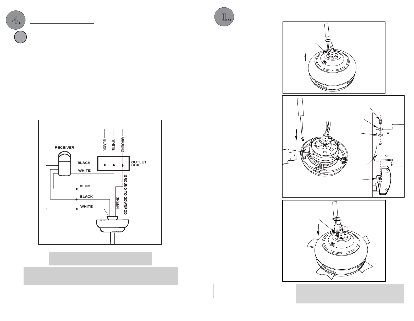
4..
4
ELECTRICAL HOOK-UP
Make the following wire connections to the receiver unit (see fig. 5) using the
A
-
wire nuts supplied.
-
connect GREEN fan wire to BARE
connect BLACK receiver unit wire to BLACK supply wire.
- connect WHITE receiver unit wire to WHITE supply wire.
- connect WHITE receiver unit wire (MOTOR N) to WHITE fan wire.
- connect BLACK receiver unit wire (MOTOR L) to BLACK fan wire.
- connect BLUE receiver unit wire (FOR LIGHT) to BLUE light wire.
- After making the wire connections, ensure the wires should be spread
apart with the grounded conductor and the equipment-grounding
conductor on one side of the outlet box and the ungrounded conductor
on the other side of the outlet box.
- Ensure the splices after being made should be turned upward and
pushed carefully up into the outlet box.
(ground) wire.
120 V
SUPPLY CIRCUIT
ATTACH THE FAN BLADES
.
11.
For model Preston or
Cove or Corbo:
Fig.2c ,2d and 2e
- Remove the cover on
the top housing.
- Attach the blades to the
fan motor assembly using
the screws, metal washer
and fibre washer. Slightly
turn the blade after
installation and repeat the
same step for the other
blades.
Fig.2c
Screw
Blade Bracket Screw
Metal Washer
Fibre Washer
Blade
Fan
Fig.5
In Quebec, the installation of this product must
be carried out by a qualified electrician.
NOTE: Once ground wires are connected, carefully tuck all wires and marrettes
into the metal outlet box making sure that the wires are clear of the
hemisphere and downrod when positioned in mounting bracket.
Pg. #8
- Re-attach the cover to
the top housing.
INST
INST
ALLA
ALLA
TION
TION
Blade Bracket
Fig.2d
Screw
Fig.2e
NOTE:
retightened where necessary, before and after
installation.
Pg. #5
All set screws must be checked and
Page 6
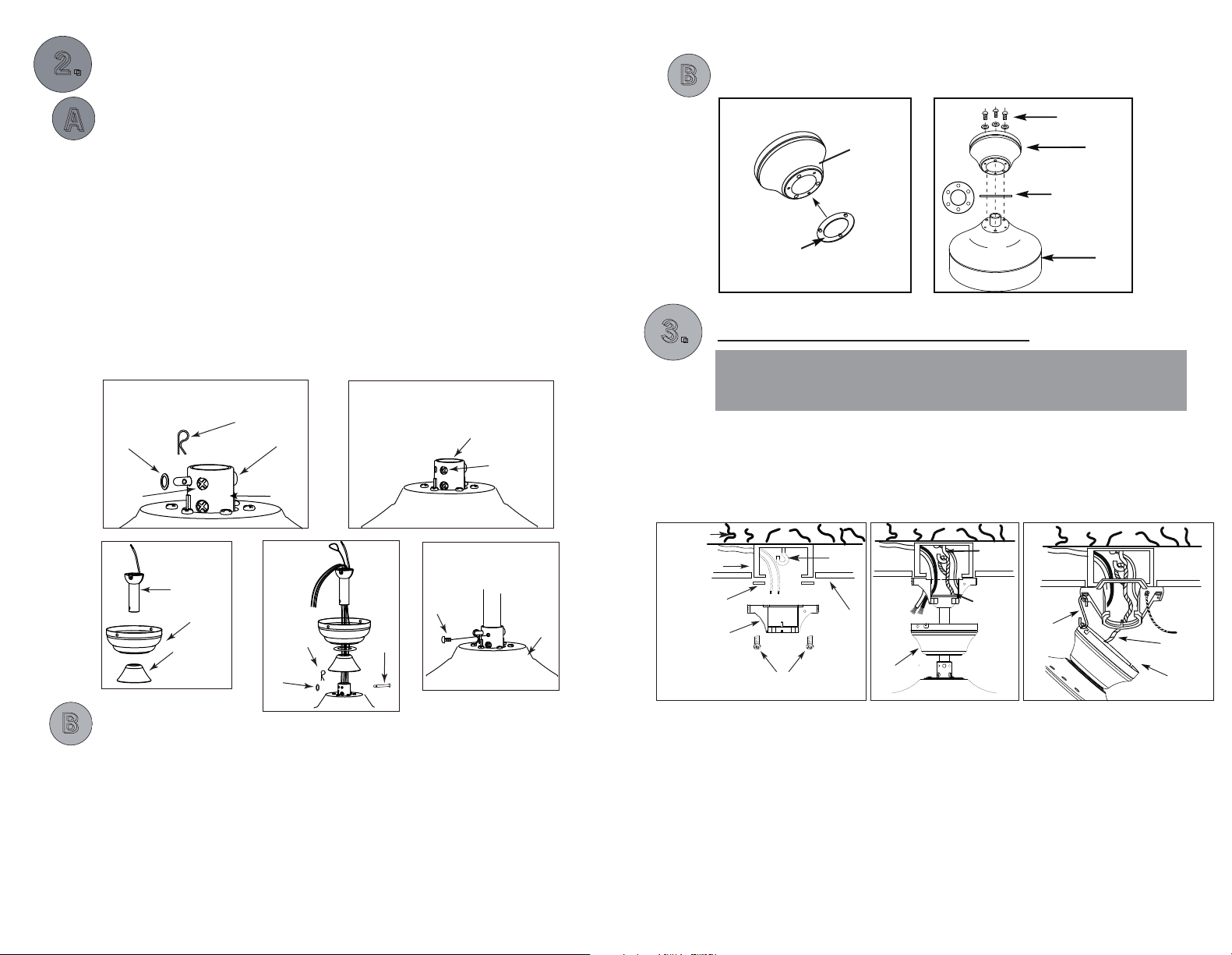
22.
fan
Remove
.
MOUNTING
B
B
FLUSH MOUNT
DOWNROD MOUNT
A
A
- Take out
-
- Loosen jam screw in yoke until it is flush with the inside surface.
- Obtain downrod, canopy and yoke cover.
- Place downrod inside canopy and yoke cover.
motor housing.
cotter pin and bolt from yoke.
- Route wires exiting motor through yoke cover, canopy and downrod.
- Insert bolt through hole in shaft and downrod. Be careful not to
damage or cut the fan wires.
- Tighten flat washer and bolt. Secure with cotter pin through hole in the
end of the bolt.
- Secure downrod in position by tightening jam screws. Slide yoke cover
down so it is flush with the motor housing.
Fig.3a
Flat
Washer
Jam
Screw
Fig.3c
Downrod
Canopy
Yoke
Cover
Cotter Pin
Bolt
Yoke
Fig.3d
Cotter
Pin
Flat
Washer
Fig.3b
Yoke
Jam
Screw
Fig.3e
Jam
Screw
Bolt
Motor
.
33.
Wood Joist
Outlet Box
Rubber Gasket
Mounting Bracket
Fig.4a
Yoke Screws
& Washers
Canopy
Rubber Ring
Fig.3f
Canopy
Rubber Bushing
Motor
Fig.3g
INSTALL MOUNTING BRACKET
WARNING: To Reduce The Risk Of Fire, Electric Shock, Or Personal
Injury, Mount To UL/CSA Listed Outlet Box Marked Acceptable for
Fan Support And Use Mounting Screws Provided With The Outlet Box.
- Install J-Hook through centre of outlet box and into the wooden joist.
- Secure mounting bracket and rubber gaskets to outlet box.
- Hang the safety cable onto the J-hook.
- Hang fan on temporary hook or mounting bracket.
Diagram Fig.4b is for Downrod Mount.
Diagram Fig.4c is for Flush Mount.
J-Hook
Safety
Cable
Fig.4b
Tomporary
Hook
Outlet box Screws
(not provided)
J-Hook
Ceiling
Canopy
Safety
Cable
Canopy
Fig.4c
B
B
FLUSH MOUNT
- Remove rubber ring from canopy.
- Place canopy on fan housing by alinging 3 larger holes of canopy over
3 existing screws on the motor housing.
- Secure canopy to motor housing by placing 3 screws and washers
(supplied in hardware package) in the 3 smaller holes in the canopy.
Pg. #6
Pg. #7
 Loading...