

Page 1
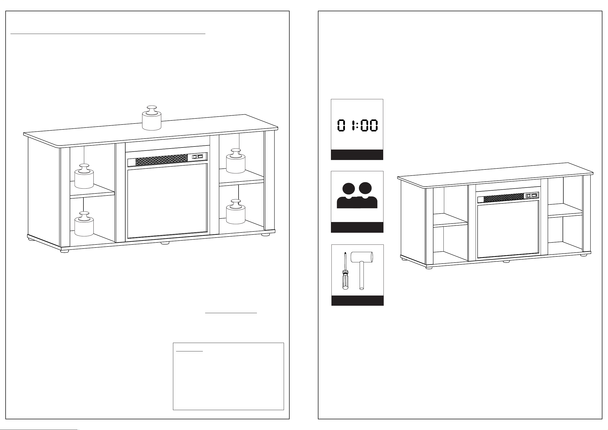
Recommended Maximum Weight
60
Assembly Instruction
TV Stand with Fireplace
Approx. 1 Hour
15
15
15
15
Recomm. 2 Person
Tools Required
*Unit in Pound(lbs.)
11
WARNING:
>This unit has been designed to support the
maximum loads shown. Exceeding these load
limits could cause sagging, instability, product
collapse, and/or serious injury.
>DO NOT allow children to climb on unit.
> Put heavier items on lower shelves.
Page 2
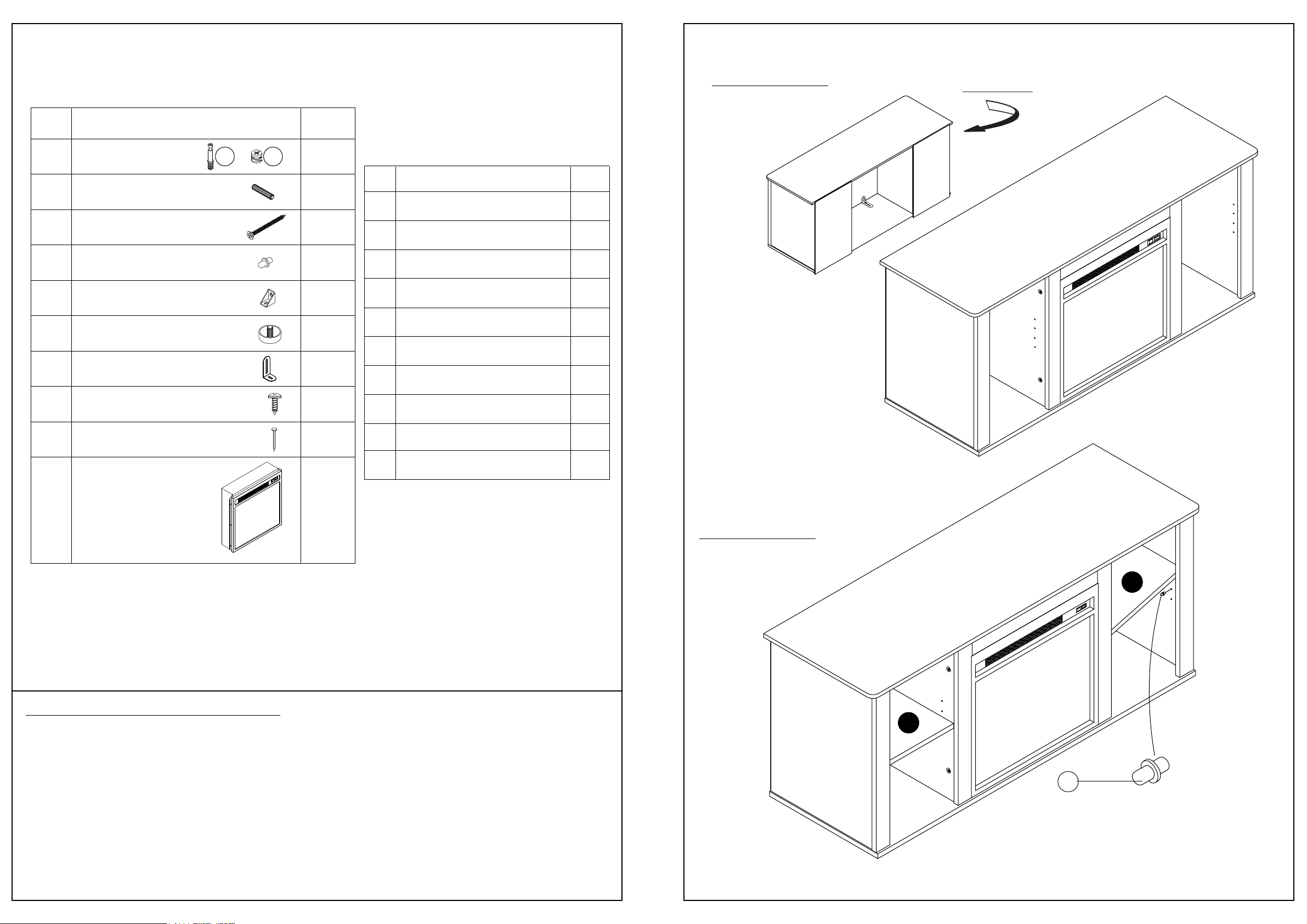
HARDWARE & PARTS LIST
NO HARDWARE LIST QTY
STEP 15
TURN 180°
1
MINIFIX
2
DOWEL
3
CHIPBOARD SCREW
4
SHELF SUPPORT
5
L BRACKET
6
PLUG LEG
7
METAL BRACKET
8
SCREW
9 POWER PIN
10 FIREPLACE
1a 1b
16pcs
16pcs
8pcs
8pcs
2pcs
6pcs
1pc
11pcs
36pcs
1pc
NO PARTS LIST QTY
A1
LEFT SIDE PANEL
A2
RIGHT CENTER PANEL
B1
LEFT CENTER PANEL
B2
RIGHT SIDE PANEL
C
RAIL PANEL
D
TOP PANEL
E
COVER PANEL
F
BOTTOM PANEL
G
SHELF PANEL
H
BACK PANEL
1pc
1pc
1pc
1pc
4pcs
1pc
1pc
1pc
2pcs
2pcs
USEFUL HINTS BEFORE YOU START:
1. Read each step carefully before starting.
2. It is important that each step is performed in correct order to avoid difficulties.
3. Identify, sort and count the parts before assembly.
4. Assemble your furniture on packaging cardboard to prevent scratch or damage.
5. Clean the product with mild cleanser using soft damped cloth. Do not use harsh or abrasive
cleanser.
STEP 16
G
G
x8pcs
4
6. Using uncompatible hardware might cause damage to product.
1 10
Page 3
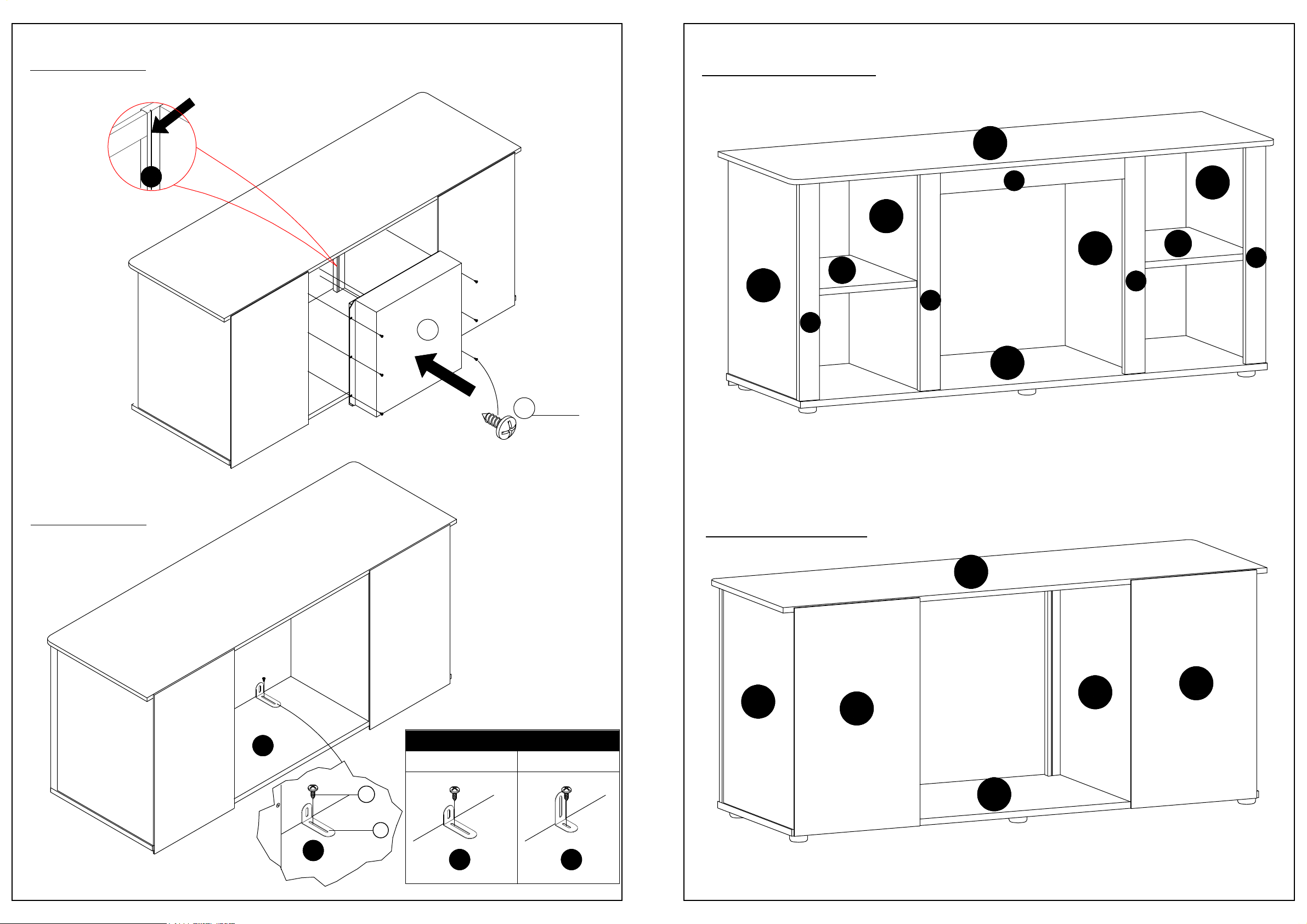
STEP 13
Fasten flange of fireplace to vertical rails(C)
with screw (8).You will screw into the
groove of the vertical rails(C).
FRONT VIEW
D
C
10
8
x6pcs
A1
C
G
B1
C
F
E
A2
B2
G
C
C
STEP 14
F
x1pc
x1pc
BACK VIEW
D
B2
B1
H
H
STYLE INSTALLATION
STYLE 1 STYLE 2
8
7
F
F
9 2
F
F
Page 4
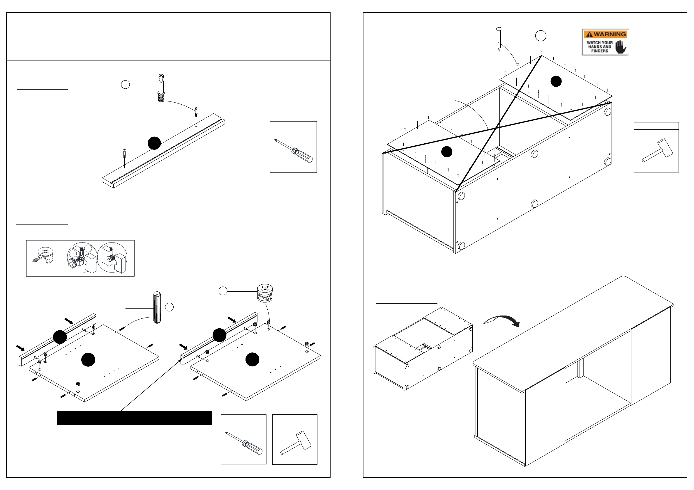
ASSEMBLY INSTRUCTIONS
BEFORE YOU BEGIN, PLEASE READ ASSEMBLY INSTRUCTIONS CAREFULLY,
FOLLOW THEM STEP BY STEP.
STEP 11
x36pcs
9
STEP 1
STEP 2
1b
1a
1a
x2pcs
C
x4
TOOL REQUIRED
Assure that the unit
H
is aligned.
TOOL REQUIRED
H
ARROW FACING
OUTWARD
TURN 180°
x8pcs
2
C
B2
Notice: The groove is on the UPPER side.
x8pcs
1b
C
TOOL REQUIRED
STEP 12
TURN 90°
A1
TOOL REQUIRED
3 8
Page 5
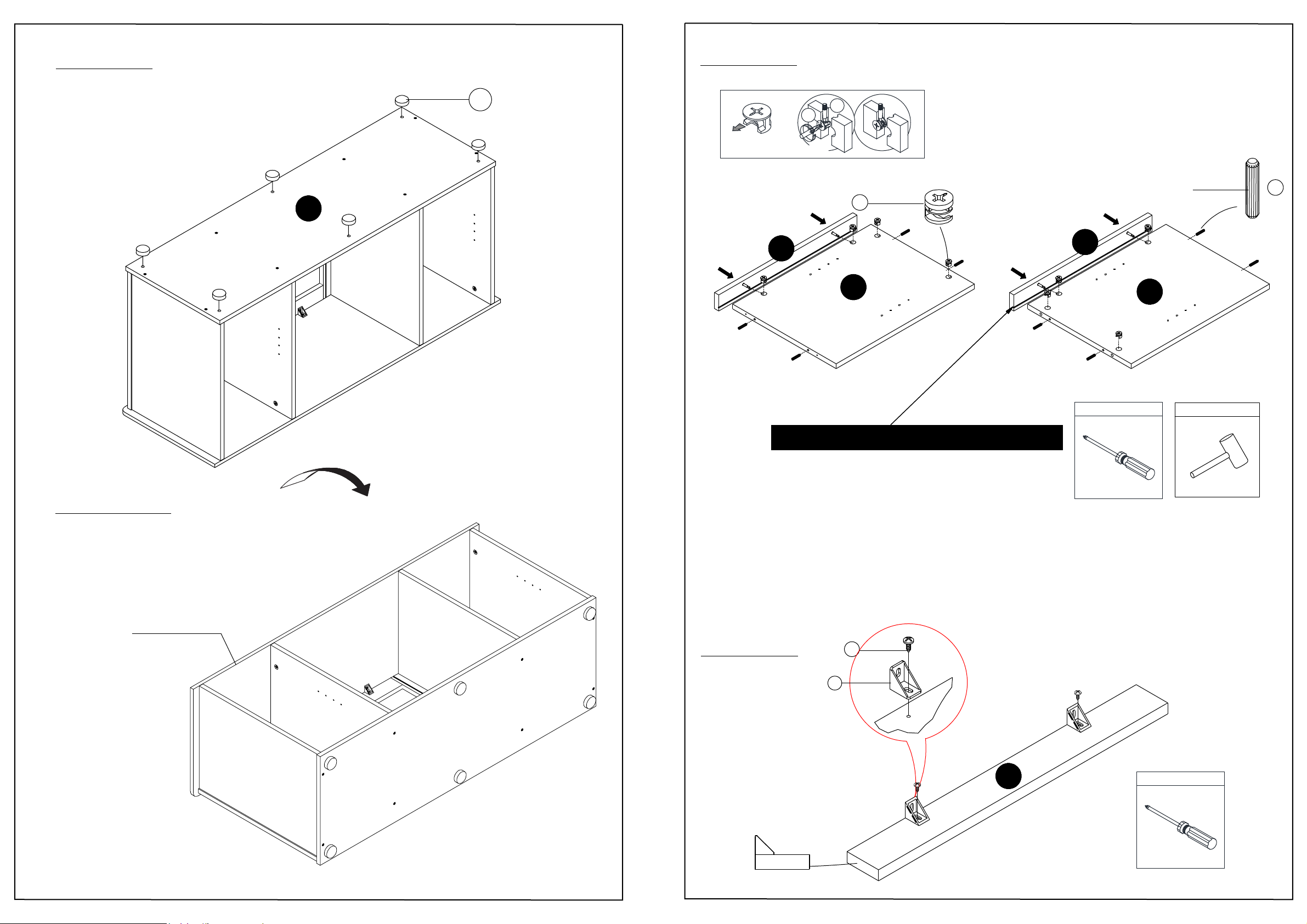
STEP 9
STEP 3
F
x6pcs
6
ARROW FACING
OUTWARD
TURN 180°
C
1b
1a
1b
A2
x8pcs
C
TOOL REQUIRED
B1
x8pcs
TOOL REQUIRED
2
STEP 10
UNFINISHED EDGE
The direction of rotation is back up
Notice: The groove is on the LOWER side.
STEP 4
5
8
x2pcs
x2pcs
7
side view
4
E
TOOL REQUIRED
Page 6
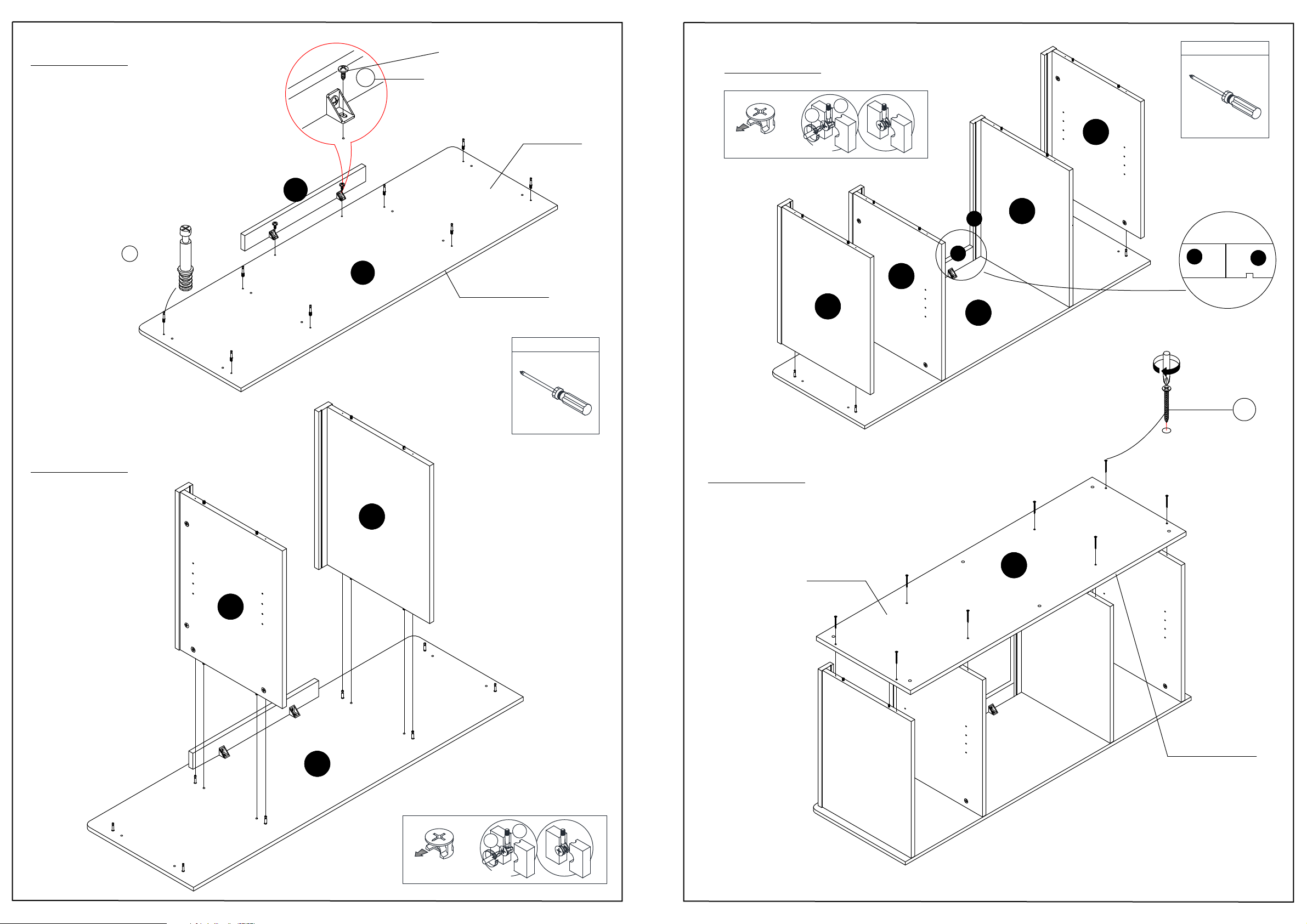
STEP 5
E
Note : Do Not fully tighten
the screw at this time.
x2pcs
8
UNFINISHED
SURFACE
STEP 7
1b
ARROW FACING
OUTWARD
TURN 180°
1a
B2
TOOL REQUIRED
STEP 6
1a
x8pcs
D
A2
UNFINISHED EDGE
TOOL REQUIRED
STEP 8
A1
B1
C
E
D
A2
Top View
E
Adjust panel (E) into parallel lines with
panel (C) and tighten the screw (8).
x8pcs
C
3
B1
D
ARROW FACING
OUTWARD
1b
TURN 180°
1a
UNFINISHED
SURFACE
F
UNFINISHED EDGE
5
6
 Loading...