

Page 1
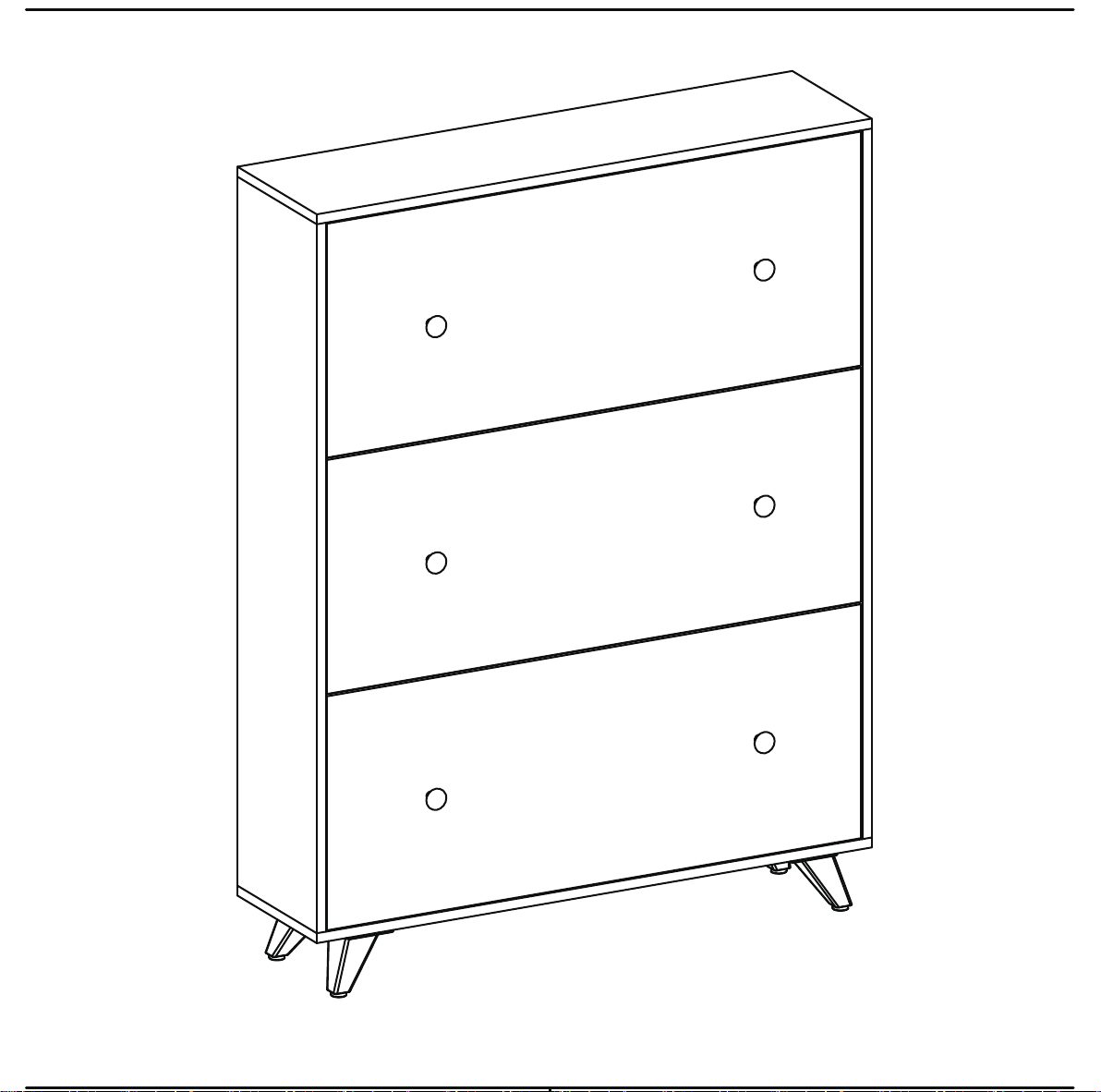
THIS INSTRUCTION BOOKLET CONTAINS IMPORTANT SAFETY INFORMATION. PLEASE READ AND KEEP FOR FUTURE REFERENCE.
Page 2
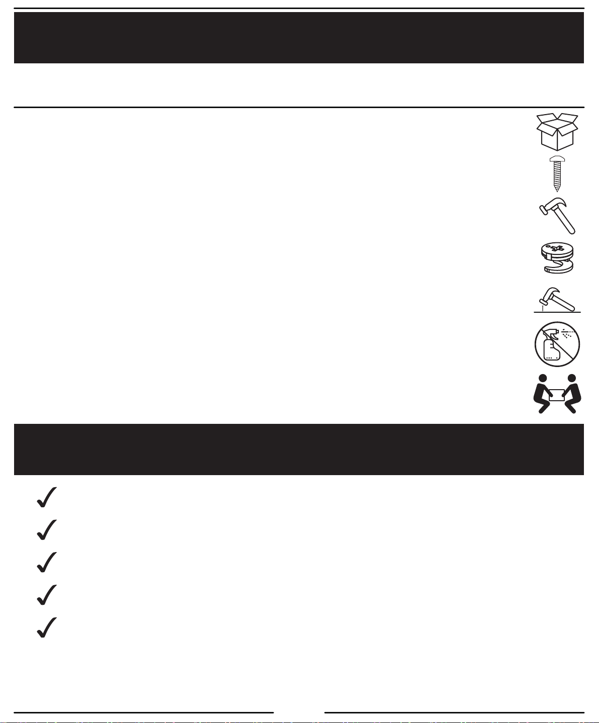
Helpful Hints
PEOPLE NEEDED FOR ASSEMBLY: 1 - 2
ESTIMATED ASSEMBLY TIME: 1 HOUR
‐ Open your item in the area you plan to keep it to avoid excessive heavy lifting.
‐ Identify, sort and count the parts before attempting assembly.
‐ Compression dowels are lightly tapped in with a hammer.
‐ Slides are labeled with a R (right) and L (left) for proper placement.
‐ Make sure to always face the point on the top of the Cam Lock towards the outer edge.
‐ Use all the nails provided for the back panel and spread them out equally.
‐ Back panel must be used to make sure your unit is sturdy.
‐ Do NOT use harsh chemicals or abrasive cleaners on this item.
‐ Never push, pull, or drag your furniture.
Before You Start
‐ Read through each step carefully and follow the proper orders
‐ Separate and count all your parts and hardware
‐ Give yourself enough room for the assembly process
‐ Have the following tools: Hammer
‐ Caution: If using a power drill or power screwdriver for screwing,
please be aware to slow down and stop when screw is tight.
Fail to do so may result in stripping the screw.
2
Page 3
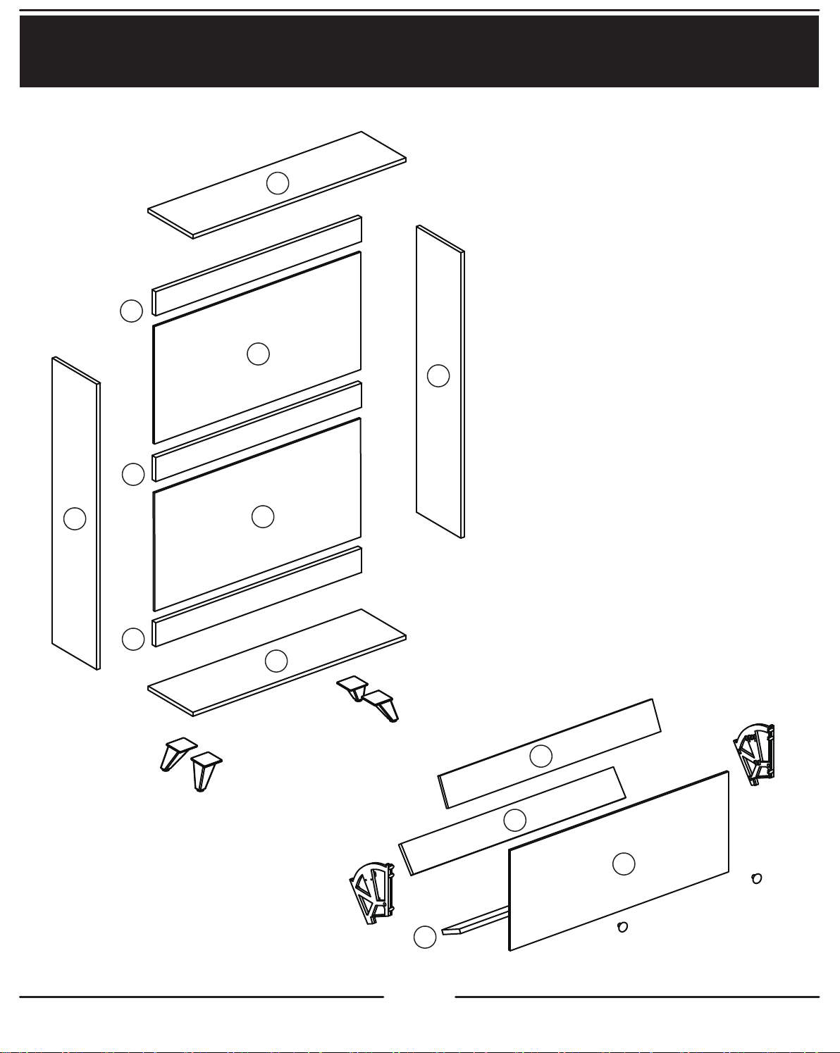
Board Identification
8
3
10
6
4
7
5
11
9
2
2
1
2
3
Page 4
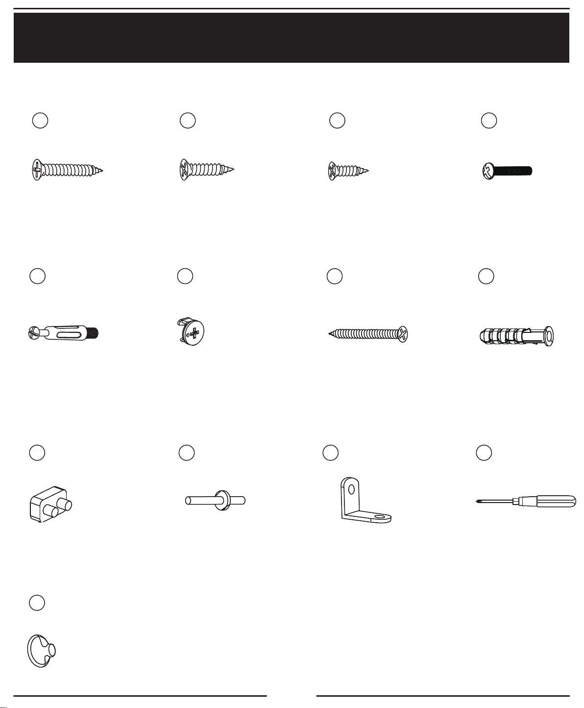
Part List
Not actual size
A
×18 ×16
E
×21
B C
F
×21
×39
12mm15mm18mm
G H
×1
D
×6
×1
J K
×6
N
×6
×6
L
×3
4
M
×1
Page 5
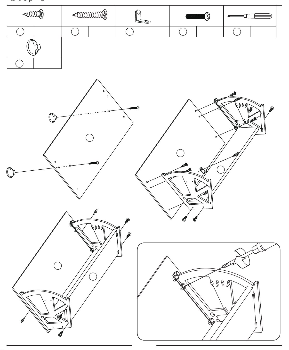
Step 1
12mm
×27C
N
×6
Fix N and 1 with D
N
N
18mm
×18A
×3L ×6D ×1
M
x3
18mm
18mm
D
18mm
1
12mm
Use 18mm
screw to punch the
corresponding hole of
the accessory to fix the
accessory with the No.
1 plate
D
1
18mm
18mm
2
12mm
1
12mm
12mm
2
Fix the accessory
to the other No.2 plate
with 12mm screws
12mm
12mm
12mm
12mm
18mm
Use 12mm screws to fix the
accessories and No. 2 plate, and
then use L and 12mm screws to
fix No. 1 plate and No. 2 plate
5
Page 6
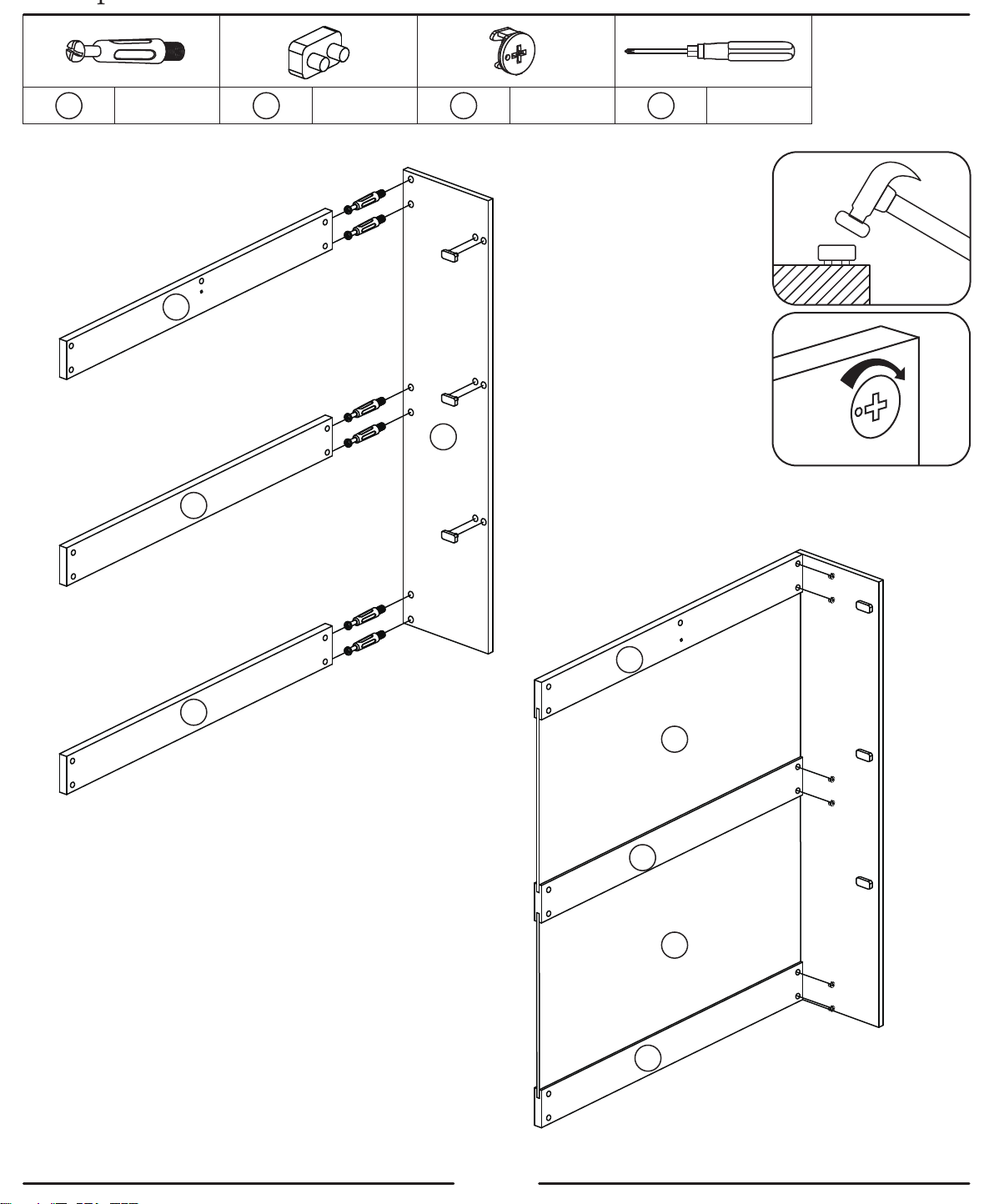
E
×6
J
×3
×6F ×1H
Connect plates 3, 4, 5 and 6
with e respectively
3
4
E
E
Fix J on the corresponding
position of plate 6 with hammer
J
E
LOCK
J
6
E
UNLOCK
Put F into 3, 4 and 5 respectively,
lock E to make the plate firmly fixed
J
E
E
3
5
Push plates 10 and 11 into the slots
in the middle of plates 3, 4 and 5
10
4
11
5
6
Page 7
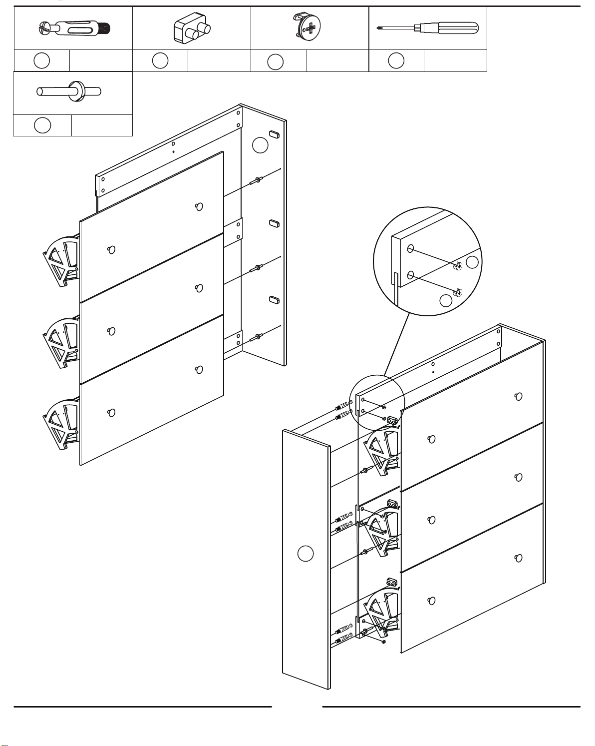
E
×6 ×3
×6K
J
F
×6
×1M
6
K
K
K
Fix the tipping bucket on
plate 6 with K
F
F
E
E
Put K and e into corresponding
positions to fix No.7 plate with
tipping bucket and back plate,
and then lock E with F
K
E
E
7
7
K
E
K
E
Page 8
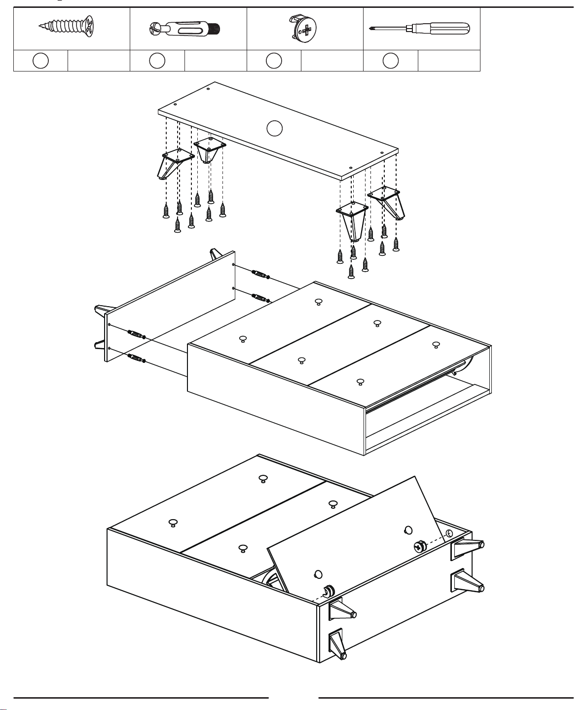
15mm
×16 ×4B ×4
E
F
8
×1M
Fix the table foot and No.8
board with 15mm screws
Use e to connect the base to the cabinet
F
F
Open the tipping bucket
again and lock e with F
8
Page 9
E
F
×5×5
M
×1
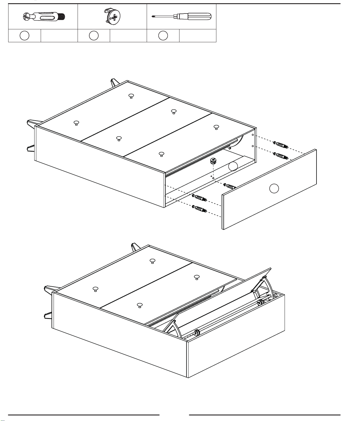
Use E to connect board 9 to the cabinet
E
3
E
E
E
E
9
F
Open the tipping bucket again and lock e with F
F
9
Page 10
12mm
×12C
2
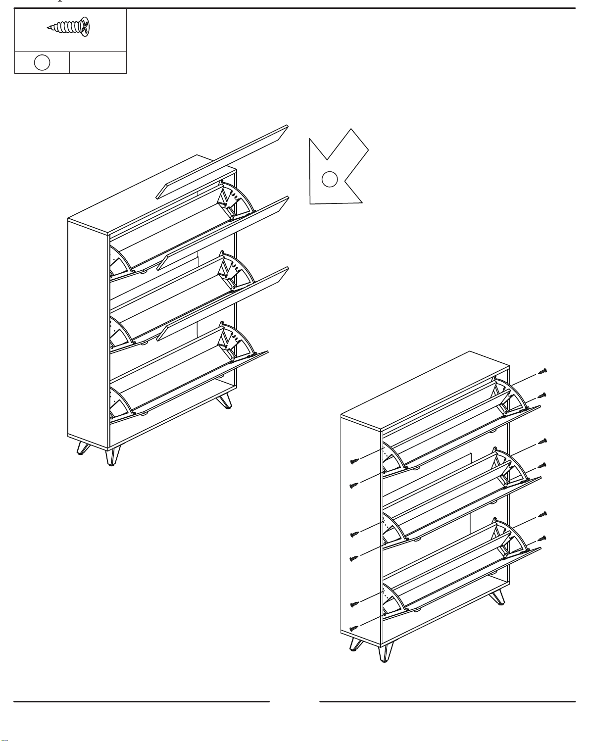
Put the No. 2 plate in the middle of the
tipping bucket and fix it with 12mm screws
10
Page 11
G
×1×1 H ×1M
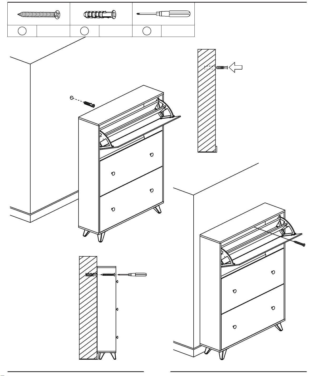
First, drill a hole in the wall
with an electric drill, and
then put the plastic part
into the hole
Then G and M are
used to fix the
cabinet on the wall
G
11
 Loading...