

Page 1
This guide
describes
how to install,
program and
operate Zipato
IR Extender.
How can I
manage all
security issues
with one
easy, intuitive
and efficient
solution?
USER
GUIDE
V1.0
IR
EXTENDER
Infrared
Page 2

COPYRIGHT
© 2015 Tri plus grupa d.o.o. All Right s Reserved. Copyright by Tri plus grupa d.o.o.
No par t of this manual may be reproduced or transmitted in any form without the
expressed, written permission of Tri plus grupa d.o.o.
TRADEMARKS
Zipato and the Zipato logo are registered Trademarks.
All other product names mentioned herein may be trademarks or registered
trademarks of their respective companies.
NOTICE
Although Zipato has attempted to ensure the accuracy of the content of this manual,
it is possible that this document may contain technical inaccuracies, typographical,
or other errors. Zipato assumes no liability for any error in this publication, and
for damages, whether direct, indirect, incidental, and consequential or otherwise,
that may result from such error, including, but not limited to loss of data or profits.
Zipato provides this publication “as is” without warranty of any kind, either express
or implied, including, but not limited to implied war ranties of merchantability or
fitness for a particular purpose. The published information in the manual is subject
to change without notice.
Zipato reserves the right to make changes in the product design, l ayout, and driver
revisions without notification to its users.
IMPORTANT SAFETY INFORMATION
To avoid contact with electrical current:
Never install an Ethernet connection in wet locations unless that connector is
specifically designed for wet locations.
Do not place Ethernet wir ing or connections in any conduit, outlet or junction box
containing electrical wiring.
Install ation of in side wir e may brin g you close t o electr ical wir e, condui t, termin als
and other elec trical facilities. Extreme caution must be used to avoid electrical
shock from such facilities. Avoid contact with all such facilities.
Ethernet wiring must be at least 2 m from bare power wiring or lightning rods and
associated wires, and at least 15 cm from other wire (antenna wires, doorbell
wires, wires from transformers to neon signs), steam or hot water pipes, and
heating ducts.
ELECTROMAGNETIC COMPATIBILITY
In proper state and when operated properly, the product complies with all the
requirements in respect of inter ference radiation according to EN 300 220-2 and
EN 301 4 89-3. The connections conducting HF signals must neither be manipulated
nor damaged.
03
IR EXTENDER
QUICK INSTALLATION GUIDE02
IR EXTENDER
QUICK INSTALLATION GUIDE www.zipato.comwww.zipato.com
Page 3
The Z XT-120 is a Z-Wave to IR extender for air-conditioner (AC), (Figure 1), it works
with any Z-Wave compliant gateway or controller by translating Z-Wave Thermostat
Commands to AC IR control code. User can select the IR code from the built-in
code librar y of ZXT-120, or use learning function, by using Z-Wave Configur ation
Commands according to the parameter table. ZXT-120 is al so with built-in
temperature sensor which allows gateway or controller to get the current room
temperature.
ZX T-120 can be configured as either “Frequently Listening Routing Slaves” (FLiRS)
or “Always Listening” node after exclusion process (before inclusion process).
FLiR S node t ype is for battery operated applications and it will enter sleep mode
frequently in order to conserve batter y consumption that can provide the flexibility if
there is out of 5 Vdc power so urce. Als o, user can place the unit in anywh ere at home.
INTRODUCTION 05
IR EX TENDER OPERATIONS 08
INSTALLATION 20
TROUBLESHOOTING 25
SPECIFICATIONS 27
IR EX TENDER CODE LIST 34
LIMITED PRODUCT WARR ANTY 40
DECLARATION OF CONFORMITY 46
INTRODUCTIONCONTENTS
Figure 1 ZXT-120
05
IR EXTENDER
QUICK INSTALLATION GUIDE04
IR EXTENDER
QUICK INSTALLATION GUIDE www.zipato.comwww.zipato.com
Page 4

Always Listening node type is for the needs of fast response application. It works
with 5 Vdc power source. Always Listening node can act as a repeater, which will retran smit the RF s ignal to ens ure that the si gnal is rec eived by it s intende d destinat ion
by routing the signal around obstacle and radio dead spots.
ZX T-120 supports Net work Wide Inclusion (NWI) and Explore Fr ames. It also
supports Z-Wave network s with multiple gateways and controllers. Like every
Z-Wave accessory, user will need to include the 4 ZXT-120 into their Z-Wave network
using the primary controller. Then, the user can use either the primary controller
or secondar y controller to configure and setup the Z XT-120 using Z-Wave’s
configuration command class. Once the configuration and setup is complete, the
controller can use Z-Wave “Thermostat commands class” to control their IRcontrolled air-conditioner through the ZXT-120.
CONTROLLER AND GATEWAY REQUIREMENTS
The Z XT-120 can work with any Z-Wave compliant controller or gateway supporting
the following Z-Wave commands.
- Configuration Command Class
- Multilevel Sensor Command Class
- Ther mostat Command Class
• Ther mostat Mode Command Class
• Ther mostat Fan Mode Command Class
• Ther mostat Set-point Command Class
BUILTIN IR CODE LIBRARY
The Built-in IR code librar y suppo rts most of the popul ar air conditioner br ands in the
mark et. Z-Wave gat eway and c ontroll er does no t need to hav e any IR cont rol code kn owled ge.
User c an use ZW ave contr oller or g ateway to s elect th e IR code acc ording to t he ZXT-120 co de
list s eparately provided through Z-Wave configuration
command.
GLOSSARY
DEVICE OR
NODE
Devices and nodes are all terms to describe anindividual Z-Wave device. These are
allinterchangeable when setting up your Z-Wavenetwork.
INCLUSION Add a Z-Wave device to the network.
EXCLUSION Delete a Z-Wave device from the network.
REMOVE
To take a device out of a group, scene or association group while that device still exists in the same
Z-Wave network.
ZWAVE
NETWORK
A collection of Z-Wave devices is controlled by primary and secondary controllers operating on the
same system. A Z-Wave network has its own unique ID code so that controllers not in the network
cannot control the system.
PRIMARY
CONTROLLER
The first controller is used to set up your devices and network. Only the Primary Controller can be
used to include or delete devices from a network. It is recommendedthat you mark the primary
controller for each network for ease in modifying your network.
SECONDARY
CONTROLLER
A controller containing network information about other devices within the network and is used
for controlling devices. Secondary controller is created from the Primary Controller and cannot
include or delete devices to the network.
INCLUSION
CONTROLLER
A controller containing network information about other devices within the network and is used for
controlling devices. Inclusion controller is created from the Primary Controller in a SIS enabled Z‐
Wave network. Inclusion Controllers have the ability to add and remove devices from the network.
07
IR EXTENDER
QUICK INSTALLATION GUIDE06
IR EXTENDER
QUICK INSTALLATION GUIDE www.zipato.comwww.zipato.com
Page 5
Before using the ZX T-120, please read the [INSTALLATION] if you need to mount
the ZXT-120 to a wall. Power up the ZXT-120 by the USB Power 5Vdc or Dry batter y
AA A x 3pcs.
• Plug-in 5Vdc power into the USB socket if operated at Always Listening
mode. Or
• Install 3x AAA batter ies if operated at FLiRS mode.
• Please refer to the section of [MOUNTING PROCEDURE].
• Remove the battery cover on the back of your ZXT-120 battery chassis.
• Mount the battery cover into the main unit with 2 screw s.
• Check the polarit y of the batteries and the “+/-” marks inside the
• battery compartment.
• Insert the batteries.
• Push the battery cover and main unit back in pl ace.
IR EXTENDER
OPERATIONS
CAUTION (battery and power adaptor safety)
• Use new batteries of the recommended type and size only.
• Never mix used and new batteries together.
• To avoid chemical leaks, remove batteries from the ZXT-120 if you do not intend to use the remote for an extended period of time.
• Dispose of used batteries properly; do not burn or bury them.
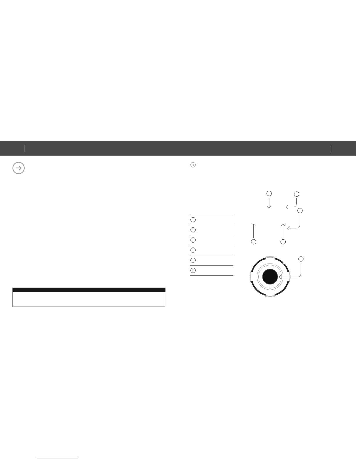
PRODUCT OVERVIEW
03
01
02
05 04
01
“PROG” Button, Learning
andLED indication
02
Temperature
sensor
03
Battery
Chassis
04
USB Power
5V DC
05
External
IR port
06
Surround IR Output for top
and 4-directions
06
09
IR EXTENDER
QUICK INSTALLATION GUIDE08
IR EXTENDER
QUICK INSTALLATION GUIDE www.zipato.comwww.zipato.com
Page 6

ZWAVE REMOTE CONTROL
01 | Select your operation mode; please refer to “Listening Mode” section.
02 | Include or Exclude the unit from the existing Z-Wave home
control network with your primar y controller.
• Refer to your primary controller instructions to process
the inclusion / exclusion setup procedure.
• When prompted by your primary controller, click once
on the PROG but ton.
• The primary controller should indicate that the action
was successful. If the controller indicates the action was
unsuccessful, please repeat the procedure.
03 | User can use either primary controller or secondar y controller
(should support configuration command class) to setup the ZXT 120 AC code by the parameter 27 (IR code number for built-in
code librar y), please refer to code list for the parameter value
then setup your AC control code.
04 | Once the configuration and setup were completed, the
controller can use Z-Wave “Thermostat commands class” to
control their IR-controlled air-conditioner with the ZXT-120.
05 | You can record down your device code under the below table for
future reference af ter setting up the ZX T-120 correctly.
ZXT120 INFORMATION
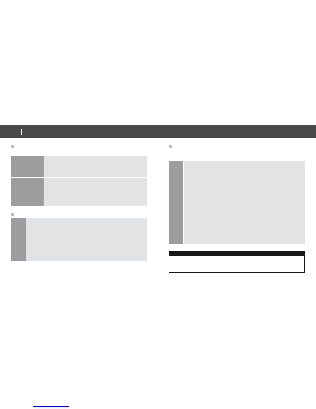
How to get the NIF “Node Information Frame” on ZX T-120 (Inclusion)
Step Setup Key LED Indication Status on ZXT-120
1
Press the PROG button on
the ZXT-120
LED flashes once then stays off (ZXT-120 will
report the supported command class)
Parameter No. and Parameter Value of configuration command
Parameter Number
Definitions Parameter Value
25 0X19
Indicate a location for IR code
learning and start learning
0-22 (0x00 0x16)
26 0X1A
Learning status register
Note:
The status value 0x01 and
0x04 will be reset to 0 when
the ZXT-120 receive a get
command to this parameter
0(0x00): Idle - this IR channel is idle
(default)
1(0x01): OK - the latest learning
process successful and completed
2(0x02): Learning - the ZXT-120 is
busy processing previous learning
request
4(0x04): Failed - the latest learning
request failed
27 0X1B
IR code number for built‐in
code library
Refer “Code list” for details
28 (0x1C)
External IR Emitter power
level
0(0x00): normal power mode
255(0xFF): high power mode (default)
CODE NUMBER:
11
IR EXTENDER
QUICK INSTALLATION GUIDE10
IR EXTENDER
QUICK INSTALLATION GUIDE www.zipato.comwww.zipato.com
Page 7
32 (0x20)
Surround IR control
-to avoid the IR interference
by disabling the surrounding
IR emitter if 2 airconditioners in a room are
used
- extend the battery life by
disabling the Surround IR
Emitters
0(0x00): disable Surround IR Emitters
255(0xFF): enable Surround IR
Emitters (default)
33 (0x21) AC function “SWING” control
0(0x00): SWING OFF
1(0x01): SWING AUTO(Default)
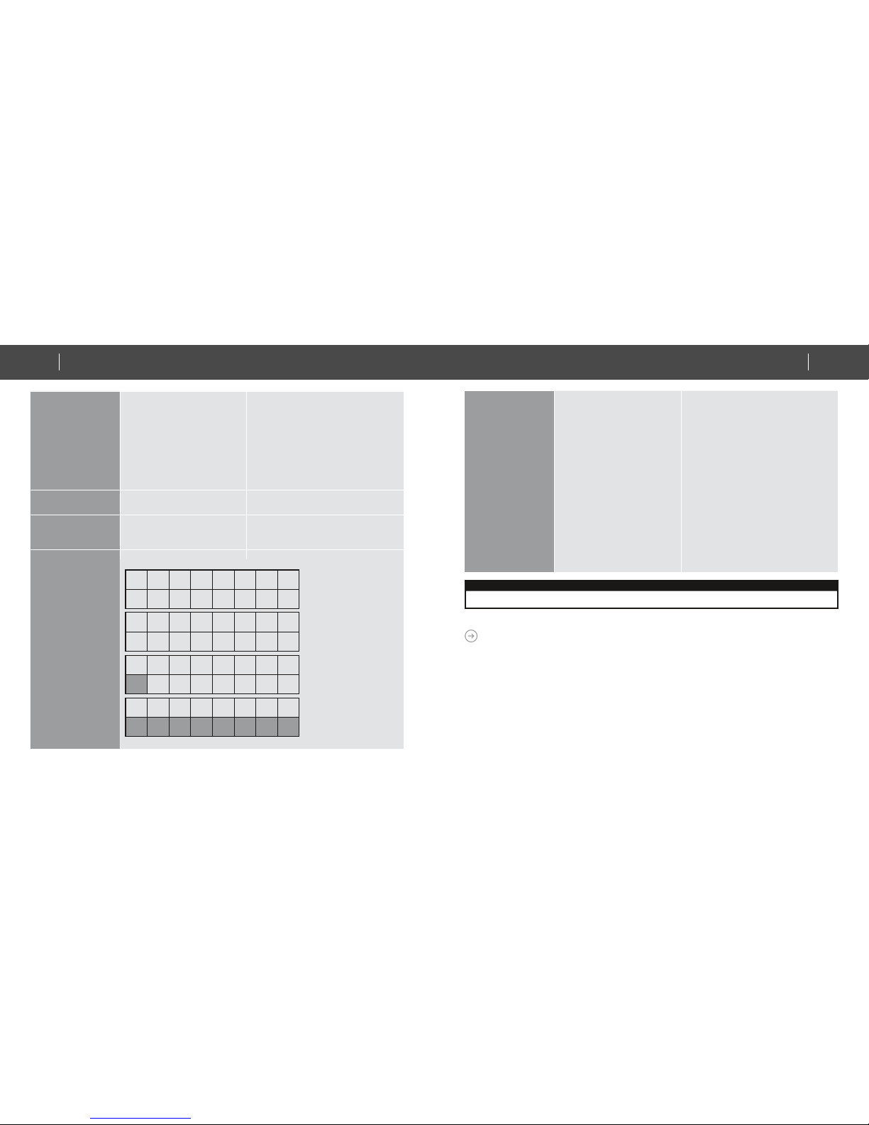
35 (0x23) Learn location status
Bit mask = 1, learn location has learn
data. Otherwise, Bit mask = 0
See figure “Learn location” as below
7 6 5 4 3 2 1 0
1 0 0 0 0 0 1 0
7 6 5 4 3 2 1 0
0 0 0 1 0 0 0 1
7 6 5 4 3 2 1 0
0 0 0 0 0 0 1
7 6 5 4 3 2 1 0
Bit Mask Byte 1
Location 0-7
Bit Mask Byte 2
Location 8-15
Bit Mask Byte 3
Location 16-22
Bit Mask Byte 4
[Reseved]
37 (0x25)
Sensor temperature
compensation
(This parameter is used to
compensate the temperature
error at temperature sensor)
Temperature offset
value.
Formula:
Display temperature
= sensor reading
value + offset value
(unit = degree C)
0x00 = 0°C (Default)
0x01 = 1°C
0x02 = 2°C
0x03 = 3°C
0x04 = 4°C
0x05 = 5°C
0xFF = -1°C
0xFE = -2°C
0xFD = -3°C
0xFC = -4°C
0xFB = -5°C
Mapping Information
• BASIC Set Value 0x00 will map to Thermostat mode Off 0x00.
• BASIC set Value 0xFF will map to Thermostat mode Resume 0x05.
LISTENING MODE CHANGE DEFAULT MODE IS FLIRS
ZX T-120 can b e configur ed as eith er “Frequ ently Lis tening Rou ting Sla ves” (FLi RS) (if you
are using battery ) or “Always Listening” (if you are using 5Vdc adaptor) before inclusion
process. Refer to Glossar y for definition of “FLiRS” and “Always Listening” node.
Important:
It is not allow ed to changin g ZXT-120 list ening mode w ithout exc lusion pro cess (do no t
change ZXT-120 listening mode while ZXT-120 is included in a networ k).
13
IR EXTENDER
QUICK INSTALLATION GUIDE12
IR EXTENDER
QUICK INSTALLATION GUIDE www.zipato.comwww.zipato.com
Page 8
How to switch Z XT-120 listening mode from “Always Listening” to
“FLiRS” (or vice verse)
Step Setup Key
LED Indication Status
on ZXT-120
1
Press and hold the PROG
button on the ZXT-120 for
around 5 seconds
LED turns ON after PROG key hold
for 5 seconds
2
Release the button and then
press the PROG button 3
times within 2 seconds
LED flashes twice then stays off
(ZXT-120 set in FLiRS mode)
OR
LED flashes four times then stays off
(ZXT-120 set in Always Listening
mode)
Inclusion/Exclusion
Step Setup Key LED Indication Status on ZXT-120
1
Refer to your primary controller
instructions to process the
inclusion/ exclusion setup
procedure.
-
2
When prompted by your
primary controller, click once
on the PROG button
LED flashes once then stay off (ZXT-120 will
report the supported command class)
The primary controller should indicate that the action was successful. If the controller
indicates the action was unsuccessful, please repeat the procedure.
IR Code Selec tion
ZXT-120 is with built-in IR AC code libr ary, user may select the IR code using
Configuration Command Class.
Step Setup Key LED Indication Status on ZXT-120
1
After included ZXT-120 to Z-Wave
controller or Gateway, go to device setup for
configuration on gateway or controller.
-
2
Input parameter number “27” and
parameter value (please look up the code
list of ZXT-120 according to your AC brand).
Then complete the configuration process.
-
3
Press the PROG button on the ZXT-120.
(this step apply when using ZRC-100 or
other portable controller for set up, if using
gateway, user can skip this step)
LED flashes once when ZXT-120
receives the configuration setting.
4
Go back to the control page of ZXT-120 on
the gateway and try the function such as
(cool, temperature set).
If the air conditioner does not respond to the
command you set on Gateway (Cool, Heat,
Auto, Temperature set etc.), repeat step 2
and 3 to select the next code on code list.
LED flashes once every time it
receives a command from
gateway.
Important Information
• Different brand or model of air conditioner has different function. For example, some air conditioner only support temperature set
from 18°C-30°C, if user set 17 °C on gateway, ZXT-120 will not respond.
• There are more than 1 code for each brand, some does not support heat, if user selected a code that does not support heat but the
original air conditioner supports heat function, please continue to try next code until the correct one is selected.
• If none of the code works on the target air conditioner, or the air conditioner brand is not shown on the code list, please select
code “000” for IR code learning (refer to instruction of IR Code Learning)
15
IR EXTENDER
QUICK INSTALLATION GUIDE14
IR EXTENDER
QUICK INSTALLATION GUIDE www.zipato.comwww.zipato.com
Page 9

IR CODE LEARNING
In case none of the code on the code list works for the targeted air conditioner, user
can use IR code learning function using configuration according to below steps:
Step Setup Key
LED Indication Status
on ZXT-120
1
Go to configuration setting
page on the gateway or ZRC100 and input parameter
number “27” and parameter
value “000” to select the
dedicated AC code number
“000” for learning.
LED flashes twice when ZXT-120
receives the configuration setting.
2
Look up below mapping table
(value 0-22) for learning,
and decide the IR setting
you intent to learn next. For
example “22°C, cool” which
matches value “5” (IR code
to be learnt will locate at “5”
in ZXT-120). Set your original
air conditioner remote at
“22°C, cool” and turn it off.
(Besides temperature and
mode, you may set other
desired settings, such as
Fan, Swing etc.)
-
3
Go to configuration setting
page on the gateway or ZRC100 and input parameter
number “25” and parameter
value “5” (in this case).
-
4
Press the PROG button on
the ZXT-120. (this step apply
when using ZRC-100 or other
portable controller for set up,
if using gateway, user can
skip this step)
LED flashes once
when ZXT-120 receives the
configuration setting.
ZXT-120 flashes once again to start
learning
5
Aim the original air
conditioner remote at ZXT120 from distance within 1-3
inches.
Press “power on” button on
the original air conditioner
remote.
If the learning is failed,
repeat step 3 to step 5.
To learn next IR code, repeat
step 2 to step 5.
LED flashes twice if
learning is successful.
LED flashes 6 times if
it’s failed.
When you encounter problem, check followings:
• Make sure your original remote is switched to power off.
• Press the key on original remote before learning mode timeout.
• Keep away from incandescent light and direct sunlight during learning.
• Make sure IR Transmitter of your original remote alight with learning diode of ZXT-120, you may also slight adjust closer or
further away the distance of two devices. Some of remotes the IR transmitter in hidden behind lens and may not installed center
of remote.
• Make sure the power is good on both devices, especially the original remote. Use fresh batteries.
IR LEARNING MAPPING TABLE PARAMETER NUMBER 25
Parameter Value
(Storage Location)
Thermostat command & IR setting
Storage in Celsius unit Storage in Fahrenheit unit
0 OFF OFF
17
IR EXTENDER
QUICK INSTALLATION GUIDE16
IR EXTENDER
QUICK INSTALLATION GUIDE www.zipato.comwww.zipato.com
Page 10

Important Information
After all learning completed, user can go back to the ZXT-120 control page on the gateway for normal operation.
• On the gateway UI, user can only use the temperature range from the mapping table, OFF, ON(RESUME), COOL, HEAT, DRY, If
user press the button of FAN, or other function on the gateway UI which is not listed in above table, ZXT-120 will not respond.
• If user only learnt ON, OFF, or part of the settings according to the above table, ZXT-120 will send the learnt data to the
air conditioner only. For example, user only learnt ON, OFF, 22°C Cool, 24°C Heat, ZXT-120 will not send IR data to air conditioner if
user set 27°C Cool on the gateway.
• ZXT-120 has been pre-defined default cool at 26°C, default heat at 22°C, when user press Cool on gateway without setting
temperature, ZXT-120 will send the learnt data of 26°C Cool to air conditioner. When user press Heat on gateway without setting
temperature, ZXT-120 will send the learnt data of 22°C Heat to air conditioner.
• There is only one code for dry mode, user can set it at any preferred temperature.
• User can still use gateway to set up scene and schedule with ZXT-120, for example, to have AC turn on at 23°C every day at 7pm,
25°C at 11pm. Just make sure the set code is learnt.
• The learning mapping table is for split air conditioner which remote control is with LCD display. For window type air conditioner
(which remote control is without LCD display), the mapping table with temperatures do not apply, due to different type of IR control
protocol. However, user may still use the OFF, or ON/RESUME, DRY key for learning. (Because the POWER key on the original
remote without LCD display is toggle, user can choose either ON key, or OFF key to learn Power key, after learning is done, press
once to turn on the air conditioner if the air conditioner is OFF, press once to turn off if the air conditioner is ON)
1 ON (resume) ON (resume)
2 19 °C cool 67 °F cool
3 20 °C cool 68 or 69 °F cool
4 21 °C cool 70 or 71 °F cool
5 22 °C cool 72 or 73 °F cool
6 23 °C cool 74 or 75 °F cool
7 24 °C cool 76 °F cool
8 25 °C cool 77 or 78 °F cool
9 26 °C cool 79 or 80 °F cool
10 27 °C cool 81 or 82 °F cool
11 28 °C cool 83 or 84 °F cool
12 19 °C heat 67 °F heat
13 20 °C heat 68 or 69 °F heat
14 21 °C heat 70 or 71 °F heat
15 22 °C heat 72 or 73 °F heat
16 23 °C heat 74 or 75 °F heat
17 24 °C heat 76 °F heat
18 25 °C heat 77 or 78 °F heat
19 26 °C heat 79 or 80 °F heat
20 27 °C heat 81 or 82 °F heat
21 28 °C heat 83 or 84 °F heat
22 Dry mode Dry mode
RESET ZXT120 TO FACTORY DEFAULT
Press and hold “PRO G” button for 10seconds on Z XT-120. Durin g the key hold period ,
RED LED lights up at around 5 seconds, then, it will flash twice until reset process is
completed at around 10 seconds.
Information
• If you are using Gateway or other Z-wave controllers to operate ZXT-120, Please follow the instruction from the gateway or other
controller.
• You can check either the specifications in the manual of your ZXT-120 or also check online at www.zipato.com for a full list of
products that can be used with your ZXT-120.
19
IR EXTENDER
QUICK INSTALLATION GUIDE18
IR EXTENDER
QUICK INSTALLATION GUIDE www.zipato.comwww.zipato.com
Page 11

MOUNTING THE ZXT120 TO A WALL
MOUNTING LOCATION PRECAUTIONS
• Before mounting, check the material and structure of the mounting location. If
the location does not have the proper material or structure, the Z XT-120 can fall
and cause injuries.
• Use commercial items that best match the wall structure and material for the
screws and other fixtures .
• Do not mo unt near a ki tchen counte r, h umidifier, or ot her locat ion in which i t can be
exposed to smoke or steam. Doing so could cause a fire or electr ical shock.
• Do not mount in locations with high humidity or large amounts of dust. Doing so
could cause a fire or electrical shock.
• Do not mount to locations subject to high temperatures, high humidity, or exposure
to water. Doing so could cause a fire or electrical shock.
• Do not mount to loc ations subject to large amounts of vibration, large jolts, or
large forces. These could cause an injury if the ZXT-120 fall s and breaks.
MOUNTING PROCEDURE PRECAUTIONS
• Do not modify part s or use the ZX T-120 in ways other than its intended use. Doing
so could cause the Z XT-120 to fall and result in an injury.
• Be sure to fully check that there are no electrical wires or pipes inside the wall
before mounting.
• If any of the screws are loose, the ZXT-120 can fall and cause an injur y. Do not
mount the ZXT-120 with the screws still loose.
• Check that the t wo screws mounted to the wall are fully inserted into the key holes
of the Z XT-120. Otherwise, the ZX T-120 can fall and cause an injur y.
• Do not mo unt the ZX T-120 so that it sticks out from the wal l edge. It could get hit b y
people’s bodies or objects and cause an injur y.
• Supplier will not be liable for any accidents or injuries that occur due to improper
mounting or handling.
• When mounting, be careful not to get your fingers pinched or injure your hands.
MOUNTING PROCEDURE PRECAUTIONS
The Z XT-120 can be mounted to a wall or wooden racks using the two key holes in
the bottom case.
Note 1: The reception sensitivity v aries depending on the antenna direction.
Note 2: Before mounting to a wall, be sure to fully read the precautions.
INSTALLATION
21
IR EXTENDER
QUICK INSTALLATION GUIDE20
IR EXTENDER
QUICK INSTALLATION GUIDE www.zipato.comwww.zipato.com
Page 12

1. Obtain two screws suitable for the wall strength and material.
2. The positional relationship between the Z XT-120 key holes and the screw
mounting positions are show n in the figure below.
Note 1: When mounting the screws to the wall, leave a space
between the wall and screw cap as shown in the figure.
4.5 mm
(3/1ins.)
48.5 mm
(1-7/8ins.)
3. Insert the ZXT-120 key holes onto the two screws mounted to the wall, and
then slide downward to secure in place.
4. After securing the ZXT-120 to the wall, connect the USB Power
or batteries and IR emitter cable to the ZXT-120.
Note 1: Check that the ZXT-120 is firmly secured to the wall
Note 2: Insert USB plug or batteries and IR emitter cable so that
they are firmly connected to the ZX T-120.
5. When removing the Z XT-120 from the wall, lift up the ZXT-120, then pull it
towards you.
6. Detach the main unit from the battery chassis by move toward to top position.
23
IR EXTENDER
QUICK INSTALLATION GUIDE22
IR EXTENDER
QUICK INSTALLATION GUIDE www.zipato.comwww.zipato.com
Page 13

WIRELESS INFORMATION
Wireless range:
This device has an open-air line-of-sight transmission distance of 100 feet which
complies with the Z-Wave standards. Performance can vary depending on the
amount of objects in between Z-Wave devices such as walls and furniture. Every
Z-Wave device set up in your network will act as a signal repeater allowing devices
to talk to each other and find alternate routes in the case of a reception dead spot.
Radio frequency limitations:
• Each w all or object (i.e.: refrigerator, bookshelf, large TV, etc) can reduce the
maximum range of 20m by up to 20 to 30%.
• Plasterboard and wooden wall s block less of the radio signal then concrete,
brick or tile walls which will have more of an effect on signal strength.
• Wall mounted Z-Wave devi ces will al so suffe r a loss of range if the y are house d
in metal junction boxes which could al so reduce the range by up to 20 to 30%.
MAINTENANCE
• Do not expose your ZXT-120 to dust, strong sunlight, humidity, high
temperatures or mechanical shocks.
• Do not use old and new bat teries together as old batteries tend to leak.
• Do not use corrosive or abrasive cleansers on your ZX T-120.
• Keep the unit dust free by wiping it with a soft, dry cloth.
• Do not disassemble your unit, it contains no user-serviceable parts.
Why won’t my ZX T-120 work with the Z-Wave devices I purchased from another
country?
Due to different countries r egulations Z-Wave pr oducts from dif ferent regions are set
to different frequencies. Before purchasing new devices make sure you have checked
that the device is compatible in your region.
How do I know which product is compatible with my ZXT-120?
ZX T-12 0 should wor k with any Z-Wa ve control ler or gatew ay that has co ntrol cap abilit y for
“Thermos tat” devi ces. All Z-Wave products al so come with the Z-Wave l ogo.
Can I use the USB port to configure ZXT-120?
No, the mini USB port only prov ides an alternati ve option for user to power the ZXT-120.
Do I need an electrician to install Z-Wave products in my house?
Installation can be simple. In some c ases all you need to do is mount the Z XT-120 to
a wall or wooden racks. You also can place the ZXT-120 on the desk and power it with
dry cell batteries.
TROUBLESHOOTING
25
IR EXTENDER
QUICK INSTALLATION GUIDE24
IR EXTENDER
QUICK INSTALLATION GUIDE www.zipato.comwww.zipato.com
Page 14

How to select my air-conditioner IR code from Z XT-120?
You should refer to the code list and look into the brand and tr y the code no.
sequentially until you find the right code. You can record down your device code
under the table for future reference after setting up the ZXT-120 correctly.
ZX T-120 is work ing on top and 4-dire ctions IR ou tput, but there is no response on
the IR emitter socket, why?
ZX T-120 supports two IR power level s for the external IR emitter to avoid saturation
of the IR receiver. You can set the IR output power level by the Par ameter Table value
(normal or high power mode) or adjust the position of your external IR emitter.
Can I use 2 or more Z XT-120 in my house? What is the max. units if yes?
Yes and it is very depend on the capability of gateway / controller. For example,
gatew ay can suppor ts up to 8, 16 or 32 ZXT-120 in a network.
How to avoid the IR interference if I am using 2 identical air conditioners in same
location but want to control them individually?
User can disable the Surround IR Output function, connect the external IR emitter
and aim it at the specific AC unit. The oper ating distance of external IR emitter is
around 100cm (High pow er mode) and 50cm (Low power m ode) but it is also depends
on the sensiti vity of the IR receiver.
MODEL NO.
rm-zx t120 .eu
rm-zx t120 .is
rm-zx t120 .in
rm-zxt120.ru
rm-zx t120 .us
RF FREQUENCY
868.4MHz (EU) (rm-zxt120.eu)
916.02MHz (IS) (rm-zxt120.i s)
865.22MHz (IN) (rm -zxt120.in)
869.02MHz (RU) (rm-zxt120.ru)
908.4MHz (US) (rm-zxt120.us)
TEMPERATURE
Meas urable range: 32 – 10 4 °F / 0 – 40 °C
Repor t resolution: 1 degree C
Operation: 0 - 40°C
Storage: -20 - 60°C
POWERED BY
USB Power DC 5V 100mA or
Dry battery A AA x 3pcs
RF OPERATING DISTANCE
up to 80ft outdoor line of sight, in
unobstructed environment
IR OPERATING DISTANCE
up to 25f t line of sight, in
unobstructed environment
IR LEARNING
Max. 23 commands
DIMENSION
Dia.=70mm, T = 18mm (Main unit)
Dia.=70mm, T = 15.5mm (Batter y
chassis)
SPECIFICATIONS
27
IR EXTENDER
QUICK INSTALLATION GUIDE26
IR EXTENDER
QUICK INSTALLATION GUIDE www.zipato.comwww.zipato.com
Page 15

WEIGHT
35g (Batter y chassis excluded)
60g (Batter y chassis included)
90g (Main + Battery chassis + AA A x3pcs)
Z-Wave device type
Basic Device Class: BASIC_TYPE_ROUTING_SLAVE
Generic Device Class: GENERIC_TYPE_THERMOSTAT
Specific Device Class: SPECIFIC_TYPE_THERMOSTAT_GENERAL_V2
Z-Wave Command Class Version Controlled Supported
COMMAND_CLASS_THERMOSTAT_MODE Version2 No Yes
COMMAND_CLASS_THERMOSTAT_SETPOINT Version2 No Yes
COMMAND_CLASS_THERMOSTAT_FAN_MODE Version2 No Ye s
COMMAND_CLASS_BATTERY Version1 No Ye s
COMMAND_CLASS_CONFIGURATION Version1 No Yes
COMMAND_CLASS_BASIC Version1 No Yes
COMMAND_CLASS_VERSION Version1 No Yes
COMMAND_CLASS_SENSOR_MULTILEVEL Version1 No Yes
COMMAND_CLASS_SWITCH_ALL Version1 No Yes
COMMAND_CLASS_MANUFACTURER_SPECIFIC Version1 No Ye s
SUPPORTED FUNCTION IN THERMOSTAT COMMAND CLASS
How to get the NIF “Node Information Frame” on ZX T-120 (Inclusion)
Z-Wave command class Description Supported
Thermostat Fan mode
Auto/Auto Low Yes
Low Yes
Auto High Yes
High Yes
Auto Medium Yes
Medium Yes
Thermostat Set point
Heating Yes
Cooling Ye s
Furnace No
Dry Air Yes
Moist Air No
Auto changeover Yes
Energy Save heating No
Energy Save cooling No
Away heating No
Thermostat Mode
Off Yes
Heat Yes
Cool Ye s
29
IR EXTENDER
QUICK INSTALLATION GUIDE28
IR EXTENDER
QUICK INSTALLATION GUIDE www.zipato.comwww.zipato.com
Page 16

Thermostat Mode
Auto Yes
Auxiliary/Emergency Heat No
Resume Yes
Fan only Yes
Furnace No
Dry Air Yes
Moist Air No
Auto Changeover Yes
Energy Save Heat No
Energy Save Cool No
AWAY No
ZXT120 FUNCTIONS AND PARAMETERS SUMMARIES:
FUNCTIONS
AIR CONDITIONER
FUNCTION
Z-WAVE COMMAND
CLASS
Z-WAVE
COMMAND
COMMAND
PARAMETER
POWER
POWER ON
COMMAND_CLASS_
THERMOSTAT
_MODE
THERMOSTAT_
MODE_SET
MODE = 5
COMMAND_CLASS_
BASIC
BASIC_SET VALUE = 0XFF
POWER OFF
COMMAND_CLASS_
THERMOSTAT
_MODE
THERMOSTAT_
MODE_SET
MODE = 0
COMMAND_CLASS_
BASIC
BASIC_SET VALUE = 0X00
MODE
AUTO
COMMAND_CLASS_
THERMOSTAT
_MODE
THERMOSTAT_
MODE_SET
MODE = 3
COOL
COMMAND_CLASS_
THERMOSTAT
_MODE
THERMOSTAT_
MODE_SET
MODE = 2
FAN
COMMAND_CLASS_
THERMOSTAT
_MODE
THERMOSTAT_
MODE_SET
MODE = 6
HEAT
COMMAND_CLASS_
THERMOSTAT
_MODE
THERMOSTAT_
MODE_SET
MODE = 1
DRY
COMMAND_CLASS_
THERMOSTAT
_MODE
THERMOSTAT_
MODE_SET
MODE = 8
AUTO Changeover
COMMAND_CLASS_
THERMOSTAT
_MODE
THERMOSTAT_
MODE_SET
MODE = 10
HEAT mode
Temperature
SETPOINT TYPE = 1
TEMPERATURE
VALUE
COOL mode
Temperature
SETPOINT TYPE = 2
TEMPERATURE
VALUE
DRY mode
Temeprature
SETPOINT TYPE = 8
TEMPERATURE
VALUE
AUTO mode
Temperature
SETPOINT TYPE
= 10
TEMPERATURE
VALUE
TEMPERATURE
SETTING
COMMAND_CLASS_
THERMOSTAT
_SETPOINT
THERMOSTAT
_SETPOINT
31
IR EXTENDER
QUICK INSTALLATION GUIDE30
IR EXTENDER
QUICK INSTALLATION GUIDE www.zipato.comwww.zipato.com
Page 17

FAN SPEED
FAN AUTO
COMMAND_CLASS_
THERMOSTAT
_FAN_MODE, v1
THERMOSTAT_
FAN_MODE_
SET
FAN MODE = 0
COMMAND_CLASS_
THERMOSTAT
_FAN_MODE, v2
THERMOSTAT_
FAN_MODE_
SET
FAN MODE = 0, 2, or
4
FAN LOW (1/3)
COMMAND_CLASS_
THERMOSTAT
_FAN_MODE, v1
THERMOSTAT_
FAN_MODE_
SET
FAN MODE = 1
COMMAND_CLASS_
THERMOSTAT
_FAN_MODE, v2
THERMOSTAT_
FAN_MODE_
SET
FAN MODE = 1
FAN MID (2/3)
- - -
COMMAND_CLASS_
THERMOSTAT
_FAN_MODE, v2
THERMOSTAT_
FAN_MODE_
SET
FAN MODE = 5
FAN HIGH (3/3)
COMMAND_CLASS_
THERMOSTAT
_FAN_MODE, v1
THERMOSTAT_
FAN_MODE_
SET
FAN MODE = 3
COMMAND_CLASS_
THERMOSTAT
_FAN_MODE, v2
THERMOSTAT_
FAN_MODE_
SET
FAN MODE = 3
SWING ON/
SWING AUTO
COMMAND_CLASS_
CONFIGURATION
CONFIGURATIO
N_SET
PARAMETER NO. =
33
SIZE = 1
VALUE = 1
SWING OFF
COMMAND_CLASS_
CONFIGURATION
CONFIGURATIO
N_SET
PARAMETER NO. =
33
SIZE = 1,
VALUE = 0
SWING
IR CODE
SETUP
COMMAND_CLASS_
CONFIGURATION
CONFIGURATIO
N_SET
PARAMETER NO. =
27
SIZE = 2
VALUE = (CODE#)
NORMAL POWER
LEVEL
COMMAND_CLASS_
CONFIGURATION
CONFIGURATIO
N_SET
PARAMETER NO. =
28
SIZE = 1
VALUE = 0
HIGH POWER
LEVEL
COMMAND_CLASS_
CONFIGURATION
CONFIGURATIO
N_SET
PARAMETER NO. =
28
SIZE = 1,
VALUE = 0xFF
DISABLE
COMMAND_CLASS_
CONFIGURATION
CONFIGURATIO
N_SET
PARAMETER NO. =
32
SIZE = 1
VALUE = 0
ENABLE
COMMAND_CLASS_
CONFIGURATION
CONFIGURATIO
N_SET
PARAMETER NO. =
32
SIZE = 1,
VALUE = 0xFF
BATTERY
LEVEL
COMMAND_CLASS_
BATTERY
BATTERY_GET
VERSION
COMMAND_CLASS_
VERSION
VERSION_GET
MANUF’ER
SPECIFIC
COMMAND_CLASS_
MANUFACTURER_
SPECIFIC
MANUFACTURER_
SPECIFIC_GET
IR TRANSMISSION
POWER
LEVEL
FRONT IR
TRANSMISSION
CONTROL
33
IR EXTENDER
QUICK INSTALLATION GUIDE32
IR EXTENDER
QUICK INSTALLATION GUIDE www.zipato.comwww.zipato.com
Page 18

COMMAND_CLAS_
SENSOR_MULTILEVEL
SENSOR_
MULTILEVEL_
GET
IR EX TENDER CODE LIST
Ascon 463
Acura 94
Aikira 174
Aircon 42 57 58
Airwell 276 432
Americool 430
Apton 67
Ariagel 13
Aucma 413 414
Aux 189 407 21 190 398 399
Azure 424
Beaver 184
Carrier
108 109 112 88 96 97 98 99 100 101
102 103 104 105 106 107 110 111 396 397
431
Chang Hong
178 179 180 5 121 122 123 124 125 126
127 134 135 136 148
Chigo 186 42 57 58
Chuanhua 37 113
TEMPERATURE SENSOR
Chunlan 19 150 151
Classic 46
Comfortstar 35 78
Conrowa 37 70 113
Consul 468 469
Coolrech 4
Coolwex 18 428
Corona 288
Daewoo 70
Daikin
6 11 1 26 313 321 324 367 2 30
32 50 211 290 325 29 162 163 261 264
265 267 31 33 266 268 269 5270 366 289
Delonghi 13 46 91
Ecoair 42
Elco 432
Electra 432 433 465 466 467
Electrolux 55 295 297
Elsonic 81
Emailair 34 153
Fedders 276
Frigidaire 273 274 275
Fujitsu
16 199 200 201 202 55 27 34 203 204
205 206 227 158 159 160 161
Galanz 4 70 83 86 277 381
35
IR EXTENDER
QUICK INSTALLATION GUIDE34
IR EXTENDER
QUICK INSTALLATION GUIDE www.zipato.comwww.zipato.com
Page 19

General 25 27 34 57
General
(FUJITSU)
16
Gorenje 46 55
Gree 18 69 292 376 429 154 155 195 15
Guangda 20 37 113
Guqiao 4
Haier
76 210 256 23 75 77 156 172 198 207
208 209 257 197
Heran 421
Hisene 68 80 382 9 427 10
Hitachi
52 53 120 227 258 259 260 291 298 299
472 39 50 51 255 262 263 375 436
Hualing 37 56 70 193
Huifeng 113
INYCIN 70
Kang Li 43
Kelon 411 12 13 14 143
Kelvinator 46 87 17
Kolin 44
Komeco 46 88
Konka 42 70
Lennox 15 18 69
LG 464 91 17 81 82 294
Lloyd 186
McQuay 196 470
Midea 54 46 40 79 55 113 78
Midea_
Toshiba
48
Miller 40 42 46 54 55 57 58
Mirage 15 18 69
Mitsubishi
194 232 233 278 280 281 282 283 284 285
286 287 302 303 304 305 307 314 320 113
244 245 246 247 248 249 42 279
Mitsubishi
Electric
4 176 228 229 230 231 233 234 235 236
237 238 239 240 315 326 392 35 37 57
93 153 287 70
Mitsubishi
(Heavy
Industries)
36 42 184 243 250 20 38 113 114 115
116 117 118 119 131 132 133 164 165 251
252 253 254 278 306 316 317 319 322
Natinal 369 402 211
NEC
127 128 129 130 135 136 137 138 139 140
141 142 146 147 148 152 166 167 168 169
170
Neo 186
Panasonic
64 95 183 191 368 323 47 61 62 63
65 92 241 242 365 378 379 437 461 462
185 293
37
IR EXTENDER
QUICK INSTALLATION GUIDE36
IR EXTENDER
QUICK INSTALLATION GUIDE www.zipato.comwww.zipato.com
Page 20

Panda 28
Philco 41
Rasonic 394
Samsung 73 74 84 425 49 300 301 438 149 171
Sanyo
45 59 60 127 128 129 130 134 135 136
137 138 139 140 141 142 146 147 148 152
166 167 168 169 170 187 218
Schnerider
Elecric
42
Shangling 70
SHARP
90 318 426 8 192 213 143 144 145 157
212 214 215 216 217 193 7 66
Shinco 22 85
Shining 70
Siemens 46
Springer 88
Super
General
57
Surrey 55
Tadiran 40 46 48 54 471
TCL 24 380 434
Tec o 426
TONAL 188
Tornado 40 46 48
Toshiba
182 56 175 177 181 186 220 221 222 223
224 225 226 219 71
Toyo 42
Toyo Cool 42
Trane 69 3 173 174
Videocon 186
VOLTAS 4 377 46
Westpoint 88
Whirlpool 13 211 271 272
White-
Westinghouse
395
Xileng 150
YORK 18 15 55 89 296
Yutu 70
39
IR EXTENDER
QUICK INSTALLATION GUIDE38
IR EXTENDER
QUICK INSTALLATION GUIDE www.zipato.comwww.zipato.com
Page 21

GENERAL TERMS
Nothi ng in this Li mited Pr oduct Wa rrant y affec ts your s tatuto ry rig hts as a con sumer.
The Limited Produc t Warr anty set for th below is given by Tri plus grupa d.o.o.
(Europe) (herein referred to as “ZIPATO”). This Limited Product Warranty is only
effective upon presentation of the proof of purchase. Upon further request by
ZIPATO, this warrant y card has to be presented, too.
EXCEPT AS EXPRESSLY SET FORTH IN THIS LIMITED WARR ANT Y, ZIPATO MAKES
NO OTHER WARR ANTIES, EXPRESS OR IMPLIED, INCLUDING A NY IMPLIED
WARR ANTIE S OF MERCHANTAB ILITY A ND FITNE SS FOR A PARTICUL AR PURP OSE.
ZIPATO EXPRESSLY DISCL AIMS ALL WARRANTIE S NOT STATED IN THIS LIMITED
WARR ANTY. ANY IMPLIED WARR ANTIES T HAT MAY BE IMPOSED BY LAW ARE
LIMITED IN DURATION TO THE LIMITED WARR ANTY PERIOD.
TO THE E XT ENT ALLOWED BY LOCAL L AW, THE REMEDIES IN THIS WARRANT Y
STATEMENT ARE CUSTOMER’S SOLE AND EXCLUSIVE REMEDIES AGAINST
ZIPATO. THEY DO NOT, HOWE VER, AFFECT OR RE STRICT THE RIGHT S YOU
HAVE AGAINST THE BUSINESS YOU BOUGHT A ZIPATO PRODUCT FROM. IN NO
EVENT WILL ZIPATO BE LIABLE FOR LOSS OF DATA OR FOR INDIRECT, SPECIAL,
INCIDENTAL, CONSEQUENTIAL (INCLUDING LOST PROFIT OR DATA), OR OTHER
DAMAGE, WHETHER BASED IN CONTR ACT, TORT, OR OTHER WISE.
HOWEVER, NOTHING IN THIS AGREEMENT LIMIT S ZIPATO’S LIABILIT Y TO YOU
(I) IN THE E VENT OF DEATH OR PERSONAL INJURY TO THE EX TENT RESULTING
FROM A NY FR AUDULENT MISREPRESENTATION ON THE PART OF ZIPATO, OR (III)
TO THE E XT ENT ARISING UNDER PART 1 OF THE CONSUMER PROTECTION ACT
1987 OF THE UNITED KINGDOM. SOME STATE S OR COUNTRIES DO NOT ALLOW:
(1) A DISCL AIMER OF IMPLIED WARRANTIES; (2) A LIMITATION ON HOW LONG AN
IMPL IED WARR ANT Y LAS TS OR THE E XCLUSI ON; OR (3) LIMI TATION OF INCI DENTAL
OR CONSEQUENTIA L DAM AGES FOR CONSUMER PRODUCTS. IN SUCH STATES OR
COUN TRIES , SOME E XCLUSIO NS OR LIMI TATIONS OF T HIS LIMI TED WAR RAN TY MAY
NOT APPLY TO YOU. THIS LIMITED WARR ANTY GIVE S YOU SPECIF IC LEGAL RI GHTS.
YOU MAY ALSO HAVE OT HER RIGHTS THAT MAY VARY FROM S TATE TO STATE OR
FROM C OUNTRY TO COUNT RY. YOU ARE ADVISED TO CONSULT APP LICABLE STATE
OR COUNTRY L AWS FOR A FULL DET ERMIN ATION OF YOUR RIGHTS.
This Limited Product Warranty applies to ZIPATO branded hardware products
(collectively referred to as “ZIPATO Hardware Products”) sold by ZIPATO (Europe),
its European subsidiaries, affiliates, authorized resellers, or country distributors
(collectively referred to as “ZIPATO Resellers”) with this Limited Product War rant y.
The term “ZIPATO Hardw are Product” is l imited to the h ardware components and all
its internal components including firmware. The term “ZIPATO Hardware Product”
DOES NOT include any software applications or programs.
LIMITED PRODUCT
WARRANTY
41
IR EXTENDER
QUICK INSTALLATION GUIDE40
IR EXTENDER
QUICK INSTALLATION GUIDE www.zipato.comwww.zipato.com
Page 22

GEOGRAPHICAL SCOPE OF THE LIMITED PRODUCT WARRANTY
This Limited Product Warrant y is applicable to Hard ware Products sold by Zipato
Resellers in all countries listed at the beginning of this document under the heading
“Countries in which this ZIPATO Limited Product Warrant y applies”. The Limited
Product Warranty will be honored in any countr y where ZIPATO or its authorized
ser vice providers offer warranty ser vice subject to the terms and conditions set
forth in this L imited Product Warrant y. However, warr anty service availability
and response times may var y from countr y to country and may al so be subject to
registration requirements.
LIMITATION OF PRODUCT WARRANTY
ZIPATO warrants that the products descr ibed below under normal use are free
from material defec ts in materials and workmanship during the Limited Product
Warranty Period set forth below (“Limited Product Warranty Period”), if the product
is used and ser viced in accordance with the user manual and other documentation
prov ided to the purchaser at the time of purc hase (or as amended from time to time).
ZIPATO does not warrant that the products will operate uninterr upted or error-free
or that all deficiencies, errors, defects or non-conformities will be cor rected.
This warranty shall not apply to problems resulting from: (a) unauthorized
alter ations or attachments; (b) negligence, abuse or misuse, including failure to
operate the product in accordance with specifications or inter face requirements;
(c) improper handling; (d) failure of goods or services not obtained from ZIPATO
or not subject to a then- effective ZIPATO warranty or maintenance agreement; (e)
improper use or storage; or (f) fire, water, acts of God or other catastrophic events.
This warranty shall also not apply to any particular product if any ZIPATO serial
number has been removed or defaced in any way.
ZIPATO IS NOT RESPONSIBLE FOR DAMAGE THAT OCCURS AS A RESULT OF YOUR
FAILURE TO FOLLOW THE INSTRUCTIONS FOR THE ZIPATO H ARDWARE PRODUCT.
LIMITED PRODUCT WARRANTY PERIOD
The Limited Produc t Warr anty Period star ts on the date of purchase from ZIPATO.
Your dated sales or delivery receipt, show ing the date of purchase of the product, is
your proof of the purchase date. You may be required to provide proof of purchase
as a condition of receiving warranty service. You are entitled to warranty service
according to the terms and conditions of this document if a repair to your ZIPATO
branded hardware is required within the Limited Product Warranty Period.
[Other than in respect of products for domestic use (in par ticular those listed in
the first and last boxes in the table below), this Limited Product Warranty extends
only to the original end user purchaser of this ZIPATO Hardware Produc t and is not
transferable to anyone who obtains ownership of the ZIPATO Hardware Product
from the original end-user purchaser.
43
IR EXTENDER
QUICK INSTALLATION GUIDE42
IR EXTENDER
QUICK INSTALLATION GUIDE www.zipato.comwww.zipato.com
Page 23

PRODUCT WARRANTY PERIOD TABLE
PRODUCT TYPE Product Warranty Period
IR EXTENDER One (1) year
IM PO RTA NT: The content of “Pr oduct Type” listed above is subject to change; please
refer to the ww w.zipato.com for latest update.
PERFORMANCE OF THE LIMITED PRODUCT WARRANTY
If a product defect occurs, ZIPATO’s sole obligation shall be to repair or replace
any defective Zipato Hardware Produc t free of charge provided it is returned to an
Authorized ZIPATO Ser vice Centre during the Limited Warranty Period. Such repair
or replacement will be rendered by Z IPATO at an Autho rized ZIPATO S ervice C entre.
All component parts or har dware products that are replaced under this Limited
Prod uct Warr anty become the pr opert y of ZIPATO. The r eplaceme nt part or produc t
takes on the remaining L imited Warranty Period of the replaced part or product.
The replacement product need not be new or of an identical make, model or part;
ZIPATO may in its discretion replace the defective product (or any part thereof) with
any reconditioned equivalent (or superior) product in all material respec ts to the
defective product.
WARRANTOR
Tri plus grupa d.o.o.
Banjavciceva 11
10 000 Zagreb
CROATIA
TEL +385 (0)1 4004 404
FAX +385 (0)1 4004 405
45
IR EXTENDER
QUICK INSTALLATION GUIDE44
IR EXTENDER
QUICK INSTALLATION GUIDE www.zipato.comwww.zipato.com
Page 24

Chan ges or modi ficatio ns not expr essly ap proved Tri p lus grup a d.o.o. fo r complia nce
could void the user’s authority to operate the equipment.
This device complies with P art 15 of the FCC Rules. Operation is subject to the
following two conditions:
(1) this device may not cause harmful inter ference, and
(2) this device must accept any interference received, including interference that
may cause undesired operation.
Le présent appareil est conforme aux CNR d’Industrie Canada applicables aux
appareils radio exempts de licence. L’exploitation est autorisée aux deux conditions
suivantes :
(1) l’appareil ne doit pas produire de brouillage, et
(2) l’utilisateur de l ’appareil doit accepter tout brouillage radioélectrique subi,
même si le brouillage est susceptible d’en compromettre le fonctionnement.
NOTE: Changes or modifications not expressly approved by Zipato for compliance
could void the user’s authorit y to operate the equipment. This equipment has been
tested and found to comply with the limits for a Cl ass B digital device, pursuant
to Par t 15 of the FCC Rules. These limits are designed to provide reasonable
protection agains t harmful interference in a residential installation. This equipment
The Manufac turer Tri plus grupa d.o.o. hereby decl ares that the product:
Zipabox Smar t home controller 1 (zbzweugv1)
In accordance with the following Directive(s): 2006/95/EC The Low Voltage
Directive, 89/336/EEC The Electromagnetic Compatibility Directive and 1999/5/
EC R&TT EC Directive is in conformity w ith the e applicable requirements of the
following documents:
EN 300 220-2 EN 60950 -1
EN 301 4 89-1
EN 301 4 89-3
EN 62479
I hereby declare that the equipment named above has been designed to comply with
the relevant sections of the above referenced specifications. The unit complies with
all applicable Essential Requirements of the Directi ves.
PERSON RESPONSIBLE FOR THIS DECLARATION:
Dean Janacek, Certification Manager
DECLARATION OF
CONFORMITY
47
IR EXTENDER
QUICK INSTALLATION GUIDE46
IR EXTENDER
QUICK INSTALLATION GUIDE www.zipato.comwww.zipato.com
Page 25

generates, uses and can radiate r adio frequency energy and, if not installed and
used in accordance with the instructions, may cause harmful interference to radio
communications. However, there is no guarantee that interference will not occur in
a particular installation.
If this equipment does cause harmful inter ference to radio or television reception,
whic h can be deter mined by t urning the e quipment o ff and on, t he user is en courage d
to try to correct the interference by one or more of the following measures:
Reorient or relocate the receiving antenna.
Increase the separation between the equipment and receiver.
Connect the equipment into an outlet on a circuit different from that to which the
receiver is connected.
DISPOSING AND RECYCLING YOUR PRODUCT
This symbol on the product or packaging means that according to local laws and
regulations needs to be disposed of separately from household waste and sent to
rec ycling be cause it c ontains e lectro nic compo nents and a b atter y. Once this p roduct
has reached the end of it s life, please take it to a collection point (rec ycle facilites)
desi gnated by your local author ities, some wil l accept your p roduct for free o r simply
drop it off at your Zipato re-seller store. By recycling the product and its packaging
in this manner you help to conser ve the environment and protect human health. At
Zipato, we understand and are commi tted to redu cing any impact our operations an d
products may have on the environment. To minimize this impact Zipato designs and
build s its prod ucts to be a s environmental ly friend ly as possi ble, by usin g recycl able,
low toxic mater ials in both products and packaging.
49
IR EXTENDER
QUICK INSTALLATION GUIDE48
IR EXTENDER
QUICK INSTALLATION GUIDE www.zipato.comwww.zipato.com
Page 26

NOTES
51
IR EXTENDER
QUICK INSTALLATION GUIDE50
IR EXTENDER
QUICK INSTALLATION GUIDE www.zipato.comwww.zipato.com
Page 27

IR EXTENDER
QUICK INSTALL ATION GUIDE
make your home smart
www.zipato.com
 Loading...