

Page 1

Quick Start Guide
v.1.1
ZIPATILE
Page 2
PACKAGING CONTENT
• ZipaTile
• ZipaTile wall holder (already attached to
the ZipaTile)
• Quick installation guide
• AC/DC power supply with adapter plugs
• Wall mounting kit
Four screws and screw anchors,
H7 plug with optional separate
wire terminals (2 male and 2 female)
OPTIONAL TOOLS NEDED
• Screwdrivers: Flathead and Philips
• Pliers
• Wire stripper
• Non-contact voltage detector
• Wire cutter
• Electrical tape
• Drill and drill bits appropriate for the
wall type
1.0 | INSTALLATION
Thank you for purchasin g ZipaTile. ZipaTile is the complete home control and autom ation
system in a form of a single device. It can be easily mounted on any wall, in any home.
Featuring large number of built-in sensors and hardware modules, ZipaTile replaces
numerous home devices such as security system, thermostat, automation controller, IP
camera, alarm siren or intercom and brings them all together in one smart and beautiful
device.
INSTALLATION REQUIREMENTS:
Wireless WiFi Router with connection to the Internet (not included in packaging)
Installation option A:
Available wall socket 100-230VAC 50/60Hz close to the postion of ZipaTile
Installation option B:
In-wall box with mains power available close to the position of ZipaTile
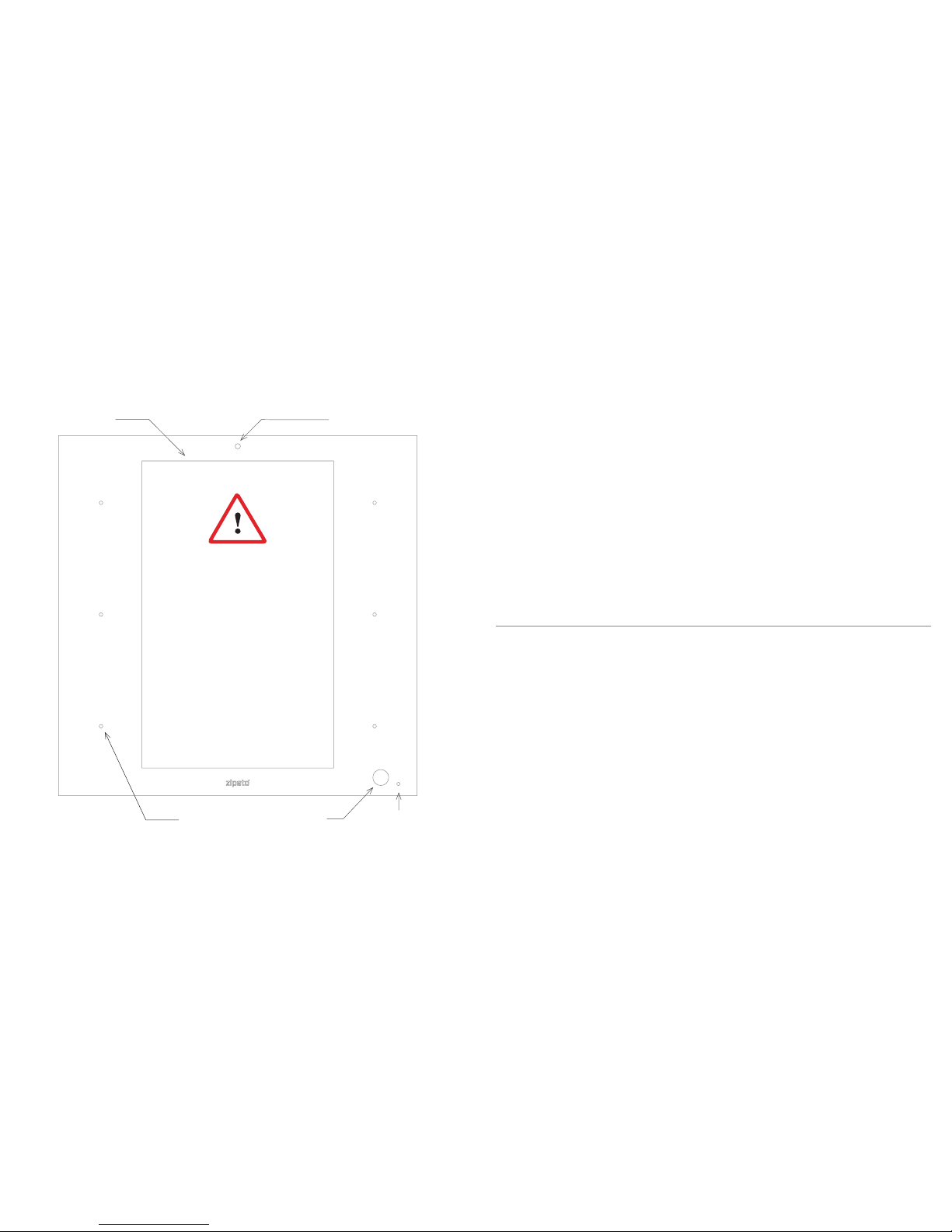
HD camera8” screen
6 scene
buttons
Light sensor
PIR sensor
CAUTION!
Installation of in-wall power
adapter and connection of
external wired devices to the
ZipaTile back panel has to be
carried out by a professional
electrician.
Page 3
2.0 | MOUNTING
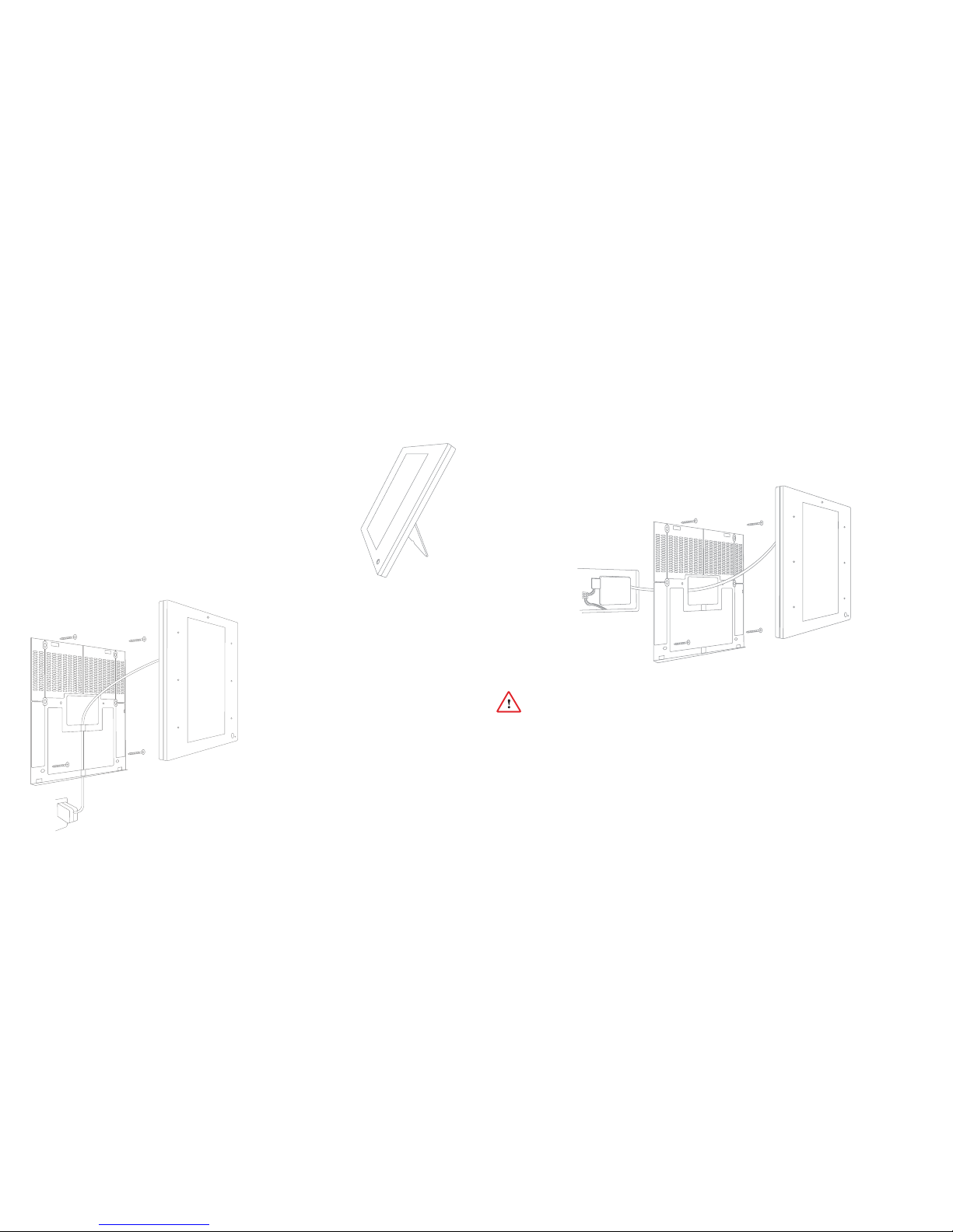
2.1 | TABLE TOP
ZipaTile is primarily intended for on wall mounting, but it can
be used on table top as well. In this case, please keep the wall
holder afixed to ZipaTile and use the built-in table top stand at
the back of the wall holder. Just plug AC/DC adapter into free
electrical socket and other side into the ZipaTile.
NOTE! ZipaTile is made for on-wall usage. Table top stand may
not be suitable for permanent usage since it can’t resist strong
touch pressure.
2.2 | WALL MOUNT WITH PLUG-IN
POWER SUPPLY
If there is no in-wall box at desired
mounting location, please use the
wire channel at the back of the wall
holder to place the power wires
behind the ZipaTile and use the
bundled plug-in power supply
to
connect to the wall socket.
NOTE! Use safety goggles and gloves
when drilling holes in the wall for
screw anchors. This product should
not be plugged in sockets that can be
turned off with a switch.
2.3 | WALL MOUNT WITH BUILT-IN POWER SUPPLY
For compact wall mounting into an in-wall box, connect the H7 pigtail wires to AC
wires and plug H7 pigtail directly onto power supply. Use bundled quick wire terminals
(male/female) to make the installation neat and tidy.
Risk of Electrical Shock
Before performing any electrical work turn OFF the power to the AC wires leading into
in-wall box at the main power source. Before starting installation make sure the power
is really off by using a non-contact voltage detector.
CAUTION! Installations should be per formed in accordance with all national and local
electrical codes. If you are unsure or have questions about the installation, please seek
an advice of a qualied electrician. Do not apply power to the ZipaTile before completing
installation. Please make sure that a proper power cut-off device is par t of your power
supply circuit (electrical fuse).
Page 4

Risk of Electrical Shock
Turn OFF the power to the AC
wires leading into in-wall box
at the main power source.
Use a non-contact voltage
detector to ensure that there
is no power to any wires in the
wall box before proceeding.
In addition to range of wireless
technologies ZipaTile also offers
connection to wired equipment
at the back of the device. This
includes external temperature
sensor (not included), one
input and two outputs or three
outputs (depending on version)
for controlling relays (please note
max. voltage and current) or for
signaling to boilers, heating or
irrigation equipment.
Dry ou tput 1
230VAC, 1A
L
N
L
N
Dry ou tput 2
230VAC, 1A
Temperature
senso r ext.
DS18B20
EU/RU/IN versions OR
Dry input
12-24 VDC
To unlock the device, just swipe up from bottom of your screen.
3.0 | SETTING UP YOUR ZIPATILE
3.1 | TURNING ON THE ZIPATILE
Press and hold (3 sec) the power button on top of the ZipaTile. Boot process
will start with the logo on the screen and it will finish when you see the ZipaTile
lock screen.
Lock screen
Dry ou tput 3
230VAC, 1A
L
N
US/IS/AU versions
Page 5

When doing this for the first time, you will
be required to enter your mobile number
and choose your location. This is needed to
receive phone and SMS security alerts, as
well as to get the local weather information
on your ZipaTile. You will need to confirm
registration in e-mail that you recieved
durring this process. Now you can login to
Zipato application.
Once registered and logged in to the Zipato
application, ZipaTile will automatically
configure itself and you will be able to
see the thermostat, security and weather
information on the home screen.
If you want to unregister yourself and restart
the ZipaTile to factory default settings, go
to ZIPATO APPLICATION > SETTINGS >
MASTER RESE T
3.2 | WIFI INTERNET CONNECTION
In order to configure your ZipaTile properly, ZipaTile has to be connected to
Internet over the Wi-Fi. If you have Wi-Fi network follow these steps:
Settings screen
1. Open the Settings app.
2. Choose Wi-Fi to view a list of available
Wi-Fi networks
3. Choose a wireless network from the list
4. If prompted, type the n etwork password
(touch the Show Password checkbox
so that you can see what you’re typing)
5. Press the Connect button. The network
is connected immediately. If not, try the
password again.
Some wireless networks do not broadcast
their names (SSID). In that case, select
three dots in the upper right corner and
choose Add network from dropdown
menu. To make the connection, type
the network name (SSID) and follow the
above procedure from step 4. When setup
completes, Wi-Fi Connected icon appears.
3.3 | ZIPATO REGISTRATION
At the home page, start ZIPATO application and select REGISTER.
NOTE! ZipaTile self-configure process may cause lack of cer tain information
within a first 10-20 minutes of using ZipaTile.
It is very important to upgrade applications to the latest version with
App Repo application before proceeding.
Login screen
Page 6

For more information check out the
users manual behind this icon within
ZipaTile apps:
Having trouble in
stalling your ZipaTile?
Contact Zipato support at:
support@zipato.com
Tri
plus grupa d.o.o.
Banjavciceva 11
10000 Zagreb
Croatia
FCC ID: 2AAU7-ZTZWUSZBEE
IC: 11391A-ZTZWUSZBEE
This device complies with part 15 of the FCC
Rules. Operation is subject to the condition that
this device does not cause harmful interference
(1) this device may not cause harmful
interference, and (2) this device must accept
any
interference received, including interference
that may cause undesired operation
Page 7

Changes or modifications not expressly approved by the party responsible for compliance
could void the user's authority to operate the equipment.
NOTE: This equipment has been tested and found to comply with the limits for a Class B
digital device, pursuant to Part 15 of the FCC Rules. These limits are designed to provide
reasonable protection against harmful interference in a residential installation. This equipment
generates, uses and can radiate radio frequency energy and, if not installed and used in
accordance with the instructions, may cause harmful interference to radio communications.
However, there is no guarantee that interference will not occur in a particular installation.
If this equipment does cause harmful interference to radio or television reception,
which can be determined by turning the equipment off and on, the user is encouraged to try to
correct the interference by one or more of the following measures:
-- Reorient or relocate the receiving antenna.
-- Increase the separation between the equipment and receiver.
-- Connect the equipment into an outlet on a circuit different
from that to which the receiver is connected.
-- Consult the dealer or an experienced radio/TV technician for help.
To maintain compliance with FCC’s RF Exposure guidelines, This equipment should be
installed and operated with minimum distance between 20cm the radiator your body: Use
only the supplied antenna.
15.19 Labelling requirements.
This device complies with part 15 of the FCC Rules. Operation is subject to the
following two conditions:
(1)This device may not cause harmful interference, and
(2) this device must accept any interference received, including interference that may
cause undesired operation.
FCC RF warning statement: the device has been evaluated to meet general RF exposure
requirement , The device can be used in portable exposure condition without restriction.
 Loading...