

Page 1
ZIPABOX2
Quick-Start
Guide
v1.3
Modular smart home server
Page 2
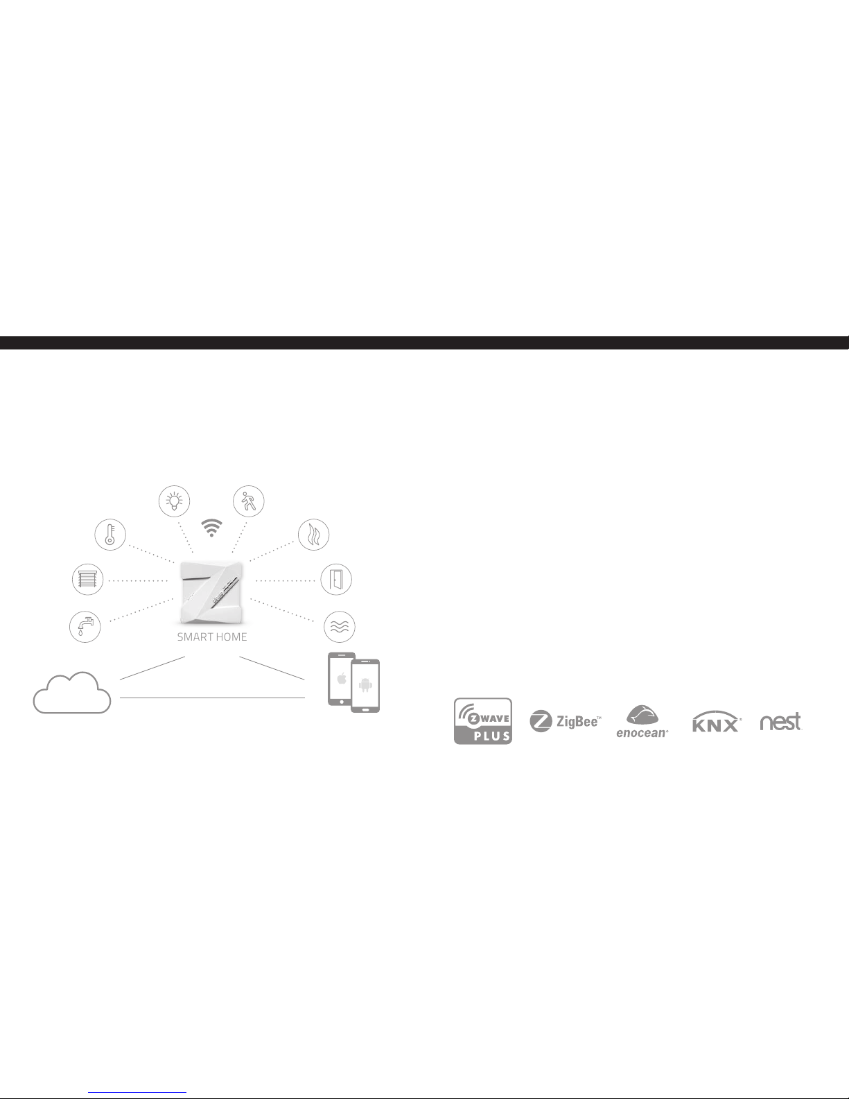
MEET YOUR ZIPABOX2
Zipato Zipabox2 lets you easily monitor, control and secure your home from
anywhere in the world. The free Zipato smart home app lets you run your
home from your smartphone, get important notifications about what’s
happening and control things in every room.
SMART HOME
SERVER
CLOUD SERVER
24/7
MOBILE APP
CONNECT EVERYTHING
ZIPABOX2 MODULES EXTENSION
With Zipabox2 you can connect various devices by using various
communication protocols and control them from your smartphone, no
matter where you are. The Zipabox 2 can be expanded with Z-Wave, ZigBee,
EnOcean, and other popular home automation protocols.
zbm.zw Zipabox - Z-Wave expansion module
zbm.zigbee Zipabox - ZigBee expansion module
zbm.serial Zipabox - Serial expansion module
zbm.security Zipabox - Securit y expansion module
zbm.p1 Zipabox - P1 expansion module
zbm.knx Zipabox - KNX expansion module
zbm.eno Zipabox - EnOcean expansion module
zbm.868 Zipabox - 868Mhz expansion module
zbm.433 Zipabox - 433Mhz expansion module
zbm.3g Zipabox - 3G expansion module
zbm.4g Zipabox - 4G expansion module
zbm.power Zipabox - Power expansion module
zbm.backupv2 Zipabox - Backup expansion module v.2
Page 3
PACKAGING CONTENT
- Power adapter 115/230 AC to 12V DC
- Ethernet cable
- Antenna* for Z-wave network (*optional)
1.1. HOW TO FIND THE SERIAL NUMBER
Your serial number is located on the left side of the Zipabox 2, make a note of it
as it will be required when registering your server online.
1.2. CONNECT TO ETHERNET
Connect your Zipabox2 to your broadband router via Ethernet cable.
The Ethernet port is located on the top of the Zipabox2.
Zipabox2 queries your DHCP server for an IP address. If you do not have a
DHCP server in your local network, after 60 seconds Zipabox2 will autoconfigure itself with a link-local IPv4 address (in 169.254.0.0/16 range).
1.3. CONNECT TO WiFi
The unit can also be connected to the WiFi. To connect to the WiFi:
1. Make sure the unit is powered off (power it off if necessary)
2. Connect power cable
3. Hold Button 1 until all LEDs start flashing sequentially in green color
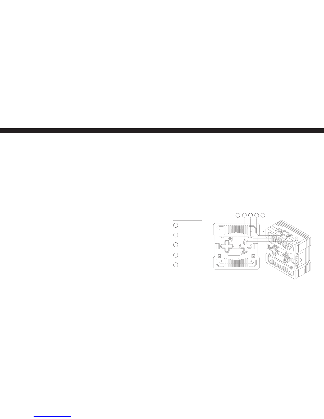
1.0. | INSTALLATION
01
Serial
number
02
Antenna*
(865-926MHz)
03
USB
port
*optional models
*
04
Ethernet
port
05
Power
input
02 03 04 05
01
*
The unit is now in WiFi AP (access point) mode. Use your mobile phone or PC to
connect to this AP. AP name is in this form: Zipabox2-<serial number>.
To connect the unit to your WiFi network:
- connect to the AP named Zipabox2-<serial number of Zipabox2>
- open http://192.168.43.1 in your browser
- select the desired AP name, input password
The unit will now try to connect to selected WiFi AP. If it succeeds connecting,
LED will light up green (red means that there was a connection problem). In
this case, reset the unit and try again, making sure the password is correct for
the selected WiFi network. Reset the unit by holding Button 2 for 4 seconds.
Page 4
1.2. MOUNT ANTENNA* - screw Z-Wave antenna to a ntenna connector (*if included)
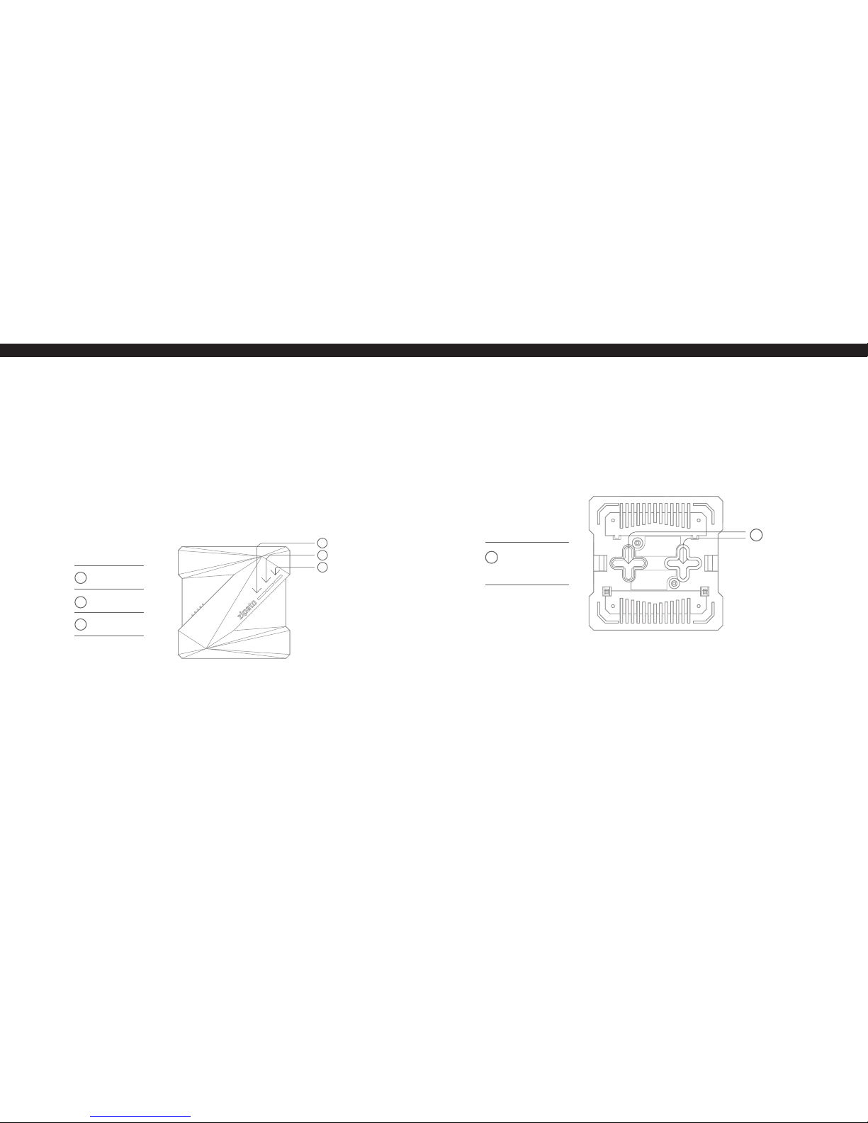
1.3. POWER UP
Plug the power adaptor into mains supply wall socket and the other end into
server. You should see following LED sequence:
01 | Steady blue light: Operating system is loading
02 | Blue light flashing: Zipato application is loading
03 | Zipabox2 getting ready or offline: slowly flashing green light
04 |
Zipabox2 ready: steady green light when stable internet connection is est ablished
1.4. POWER DOWN
If the unit is equipped with a battery, to turn it off completely, disconnect the
power cable, then hold Button 2 for 4 seconds.
1.5. RESET
To reset Zipabox2, hold Button 2 for 4 seconds.
01
02
03
2.1. WALL MOUNTING
Drill holes in the wall and insert the wall plugs if fixing into pla ster or brick wall.
Drill two holes, fix the screws and hook the Zipabox2 onto the screw heads.
Make sure swivel antenna is in vertical position.
2.1. DIN RAIL MOUNTING
Make enough space for Zipabox2 on your DIN-rail. Hook upper fitters on the
back of your Zipabox2 t o the DIN rail and press Zipabox2 slightly to snap lower
fitters.
01
Holes for fixing
Zipabox2 on
screw heads
01
2.0. | MOUNTING
01
02
03
Button 1
Button 2
LED indicator
CAUTION
Please contact a certified electrician if working with mains powered electrical box.
Page 5

3.1. REGISTER YOUR ACCOUNT
Option A) Start with the free Zipato smart home application,
click on the “Register” button and create a new account.
Option B) Open a browser window on your computer, go to
the following URL: my.zipato.com and register a new account.
To benefit from Zipato Smart Home ser vices you will need to set up your
Zipato account, create your Smart Home System and register your Zipabox2.
3.0. | ACCOUNT CREATION AND
REGISTRATION
2.3. TABLE TOP
You can place your Zipabox2 on any table top. Just make sure that swivel
antenna is in vertical position (if equipped with).
01
02
01
02
01
02
03
Upper fitters
Lower fitters
01
02
03
Button 1
Button 2
LED indicator
3.2. CREATE YOUR SYSTEM
Go to System in the main menu and click “+” to create a new System.
3.3. REGISTER YOUR ZIPABOX2
Once you are logged in to your System, go to Devices and click “+” to register a
new ser ver. If you are using the mobile app while you are connected to the same
IP network as your Zipabox2, you should be able to see your Zipabox2 with the
status “Unregistered” in the list of servers. In this case, you can just click on it
to get Register option. Otherwise just enter the serial number of your Zipabox2
manually (see 1.1. How to find the serial number).
Page 6

SYSTEM
ARM Cortex-A7 Quad-Core
1.3GHz CPU
256MB RAM
4GB FL ASH
NETWORK
Ethernet 100BASE-T X
WiFi 8 02.11 bgn
Bluetooth 4.0
Radio module ( Z-Wave, ZigB ee,
EnOce an, 433 MHz, etc...)*
OPERATING SYSTEM
Linux (4.1x kernel)
ACCESSORIES
CAT5e U TP patch L AN Cable
Antenna (Z-Wave, ZigBee, EnOcean,
433 MHz, etc...)*
POWER
Power input: 9-12VDC
Inter nal backup batt ery (900mAh)
Power supply input: 100-240VAC,
50/60 Hz
Power usage: Idle: 1.2W, Max: 2.4W
ENVIRONMENTAL
Temperature Range:
Oper ating: 0°C to 40°C (32°F to 104°F)
Storage: -25°C to 70°C (-13°F to 158°F)
Humidity: 5% to 95% non-condensing
LEDS
2 programmable buttons
2 programmable green LEDs
1 programmable RGB LEDs
I/O
USB 2.0 downst ream port
REGULATORY COMPLIANCE
Safety: UL
EMC: FCC, CE
RoHS
PHYSICAL DIMENSION
86 (L) x 8 6 (W) x 47 (H) millimeters
3.4 (L) x 3.4 (W ) x 1.9 (H) inch es
AUTOMATION OPTION
Remote automation software
Online remote control interface
WARRANTY
1 year standard
5.0. | SPECIFICATIONS
*optional models
Page 7

6.0. | SAFETY
6.1. IMPORTANT SAFETY INSTRUCTIONS
• Read, keep and follow these instruc tions.
• Heed all warnings.
• Do not use this product near water or expose the product to dripping or
splashing of water or liquid of any kind.
• Clean only with a dry cloth.
• Do not install near any heat sources such as radiators, heat registers, stoves
or other apparatus (including amplif iers) that produce heat.
• Only use at tachments and accessories specified by the manufacturer.
Disconnect the network cable and power ada pter or any other connected peripher als
if any of t he following conditions exist :
• The power cord or connec tor is damaged or fr ayed.
• The Zipabox2 or cables are exposed to rain, water/fluids, or excessive moisture.
• The Zipabox2 power adapter is damaged a nd you suspec t it needs to be s erviced.
••
Avoid installing the Zipabox2 near or inside sources of electromagnetic
interference.
(Waste Electrical & Electronic Equipment)
(Applicable in countries with sepa rate collec tion systems)
This marking on the product, accessories or literature indicates that the product and
its electronic accessories (e.g. charger, headset , USB cable) should not be disposed of
with other household waste. To prevent possible harm to the environment or human
health from uncontrolled waste disposal, please separate these items from other
types of waste and recycle them responsibly to promote the sustainable reuse of
material resources.
Household users should contact either the retailer where they purchased this
product, or their local government office, for details of where and how they can take
these items for environmentally safe recycling.
Business users should contact their supplier and check the terms and conditions of
the pu rchase co ntract . This prod uct and it s electr onic acces sories sh ould not be mi xed
with other commercial wa stes for disposal. (Applicable in countries with separate
collection systems)
At Zipato, we understand and are committed to reducing any impact our operations
and products may have on the environment. To minimize this impact Zipato designs
and builds its products to be as environmentally friendly as possible, by using
recyclable, low toxic materials in both products and packag ing.
7.0. | DISPOSING AND RECYCLING YOUR
PRODUCT
Page 8

Disclaimer
Some content and ser vices accessible through this device belong to third parties and
are pr otected b y copyrigh t, patent , tradem ark and/or ot her intelle ctual pr operty l aws.
Such content and ser vices are provided solely for your personal non-commercial use.
You may not use any content or services in a manner that has not been authorised by
the content owner or service provider.
Without limiting the foregoing, unless expressly authorised by the applicable content
owner o r service p rovider, you may n ot modify, co py, republish, u pload, pos t, tran smit,
translate, sell, create deriv ative work s, exploit , or distribute in any manner or medium
any content or services displayed through this device.
Tri plus gr upa d.o.o. w arrant s this pro duct (the “ Product ”) aga inst defe cts in mat erials
and/or workmanship under normal use for a period of ONE (1) YEAR from t he date of
purchase by the original purchaser (“Warranty Period”). If a defect arises and a valid
claim is received within the Warranty Period, then as your sole remedy (and Tri plus
grupa’ sole liability), Tri plus grupa will at its option either 1) repair the defect at no
charge, using new or refurbished replacement part s, or 2) replace the Product with a
new pro duct tha t is functi onally eq uivalent t o the origi nal, in each c ase with in 30 days
following receipt of the returned Product. A replacement product or part, assumes
the remaini ng warran ty of the or iginal Pro duct. Whe n a Product o r part is exc hanged,
any replacement item becomes your property and the replaced Product or par t
8.0. | ONE 1 YEAR LIMITED WARRANTY
becomes Tri plus grupa’ proper ty. Obtaining Service: To obtain warranty service,
visit https://community.zipato.com to open a service request. Please be prepared to
describe the Product that needs ser vice and the nature of the problem. A purchase
receipt is required. The Product must be insured, and shipped freight prepaid and
securely packaged. You must contact support for a Return Material Authorization
Numbe r (“RMA Numbe r”) befor e shipping any Produ ct, and in clude the RMA N umber,
a copy of yo ur purchase rece ipt and a desc ription of t he problem yo u are exper iencing
with the Product. Any claim under this Limited Warranty must be submitted to Tri
plus gr upa before t he end of the Wa rrant y Period. E xclusions: T his warr anty doe s not
apply to: a) damage caused by failure to follow instructions relating to the Product’s
use or the inst allation of components; b) damage caused by accident, abuse, misuse,
transpor t, neglect, fire, floods, earthquake or other external causes; c) damage
caus ed by serv ice perf ormed by a nyone who is n ot an auth orized rep resent ative of Tri
plus gr upa; d) acce ssories used in conjunction with a covered Produc t; e) a Product or
par t that has b een modif ied to alte r functio nality o r capabil ity; f) it ems intend ed to be
peri odically r eplaced by th e purchas er during th e normal li fe of the Prod uct, incl uding,
without limitation, batteries, bulbs or cables; g) a Product that is used commercially
or for a commercial pur pose, in each case a s determined by SmartT hings.
EXCEPT FOR BODILY INJURY, TRI PLUS GRUPA SHALL NOT BE LIABLE FOR I ANY
LOST PROFITS, COST OF PROCUREMENT OF SUBSTITUTE PRODUCTS, OR ANY
INCIDENTAL OR CONSEQUENTIAL DAMAGES, OR II ANY AMOUNTS IN EXCESS OF
THE PURCHASE PRICE FOR THE PRODUCT, IN EACH CASE WHETHER RESULTING
FROM THE USE OF OR INABILITY TO USE THIS PRODUC T, OR ARISING OUT OF
Page 9

ANY BREACH OF THIS WARRANTY, EVEN IF COMPANY HAS BEEN ADVISED
OF THE POSSIBILITY OF SUCH DAMAGES. SOME STATES DO NOT ALLOW THE
EXCLUSION OR LIMITATION OF INCIDENTAL OR CONSEQUENTIAL DAMAGES,
SO THE ABOVE LIMITATION AND EXCLUSIONS MAY NOT APPLY TO YOU. TO THE
EX TENT PERMIT TED BY APPL ICABLE L AW, TRI PLUS GRUPA DIS CLAIMS ANY AND
ALL STATUTORY OR IMPLIED WARRANTIES, INCLUDING WITHOUT LIMITATION,
WARRANTIES OF MERCHANTABILITY, FITNESS FOR A PARTICULAR PURPOSE
AND WARRANTIES AGAINST HIDDEN OR LATENT DEFEC TS. IF TRI PLUS GRUPA
CANNOT LAWFULLY DISCLAIM STATUTORY OR IMPLIED WARRANTIES, THEN TO
THE EXTENT PERMITTED BY LAW, ALL SUCH WARRANTIES SHALL BE LIMITED
IN DURATION TO THE WARRANTY PERIOD. SOME STATES DO NOT ALLOW
LIMITATIONS ON HOW LONG AN IMPLIED WARRANTY L AS TS, SO THE ABOVE
LIMITATIONS MAY NOT APPLY TO YOU.
This warranty gives you specific legal rights and you may also have other rights,
which vary from countr y to country. To exercise your rights under this warranty,
please follow the instructions above under the heading “Obtaining Service”, or
contact Zipato at Tri plus grupa d.o.o., Banjavciceva 11, 10000 Zagreb, Cro atia.
Zipato is a registered tradema rk of Tri plus grupa d.o.o.
Manufacturer / Importer for Croat ia:
Tri plus grupa d.o.o.
Banjavciceva 11, 10000 Zagreb
Croatia
9.0. | DECLARATION OF CONFORMITY
We, Tri plus grupa d.o.o., Croatia, 10000 Zagreb Banjavciceva 11, declare that the
product Zipabox2, is in compliance with all the technical regulations applicable to
the product within the scope of Council Directives 2014/53/EU.
Sebastian Popovic, CEO
Manufacturer’s Name: Tri plus grupa d.o.o.
Address: Banjavciceva 11, 10000 Zagreb, Croatia
Product name: Zipabox2
Model number: zb2.main
Operating Temperature: -10° C to 35° C
This d evice in com pliance w ith the e ssenti al requi rement s and othe r relevan t provisi ons
of Directive 2014/53/EU. All essential radio test suites have been carried out .
1. CAUT ION : RISK OF EX PLOSION IF BATTER Y IS REPLACE D BY AN INCORREC T TYPE.
DISPOSE OF USED BATTERIES ACCORDING TO THE INSTRUCTIONS
2. The produc t shall only be connected to a USB interface of version USB 2.0
3. Adapter shall be installed near the equipment and shall be easily accessible.
4. The plug considered as disconnect device of adapter.
5. The device complies with RF specifications when the device used at 0mm from
your body.
Page 10

RF output power: This product can be used across EU member states.
Changes or modifications not expressly approved by the party responsible for
compliance could void the user’s authority to operate the equipment.
NOTE
This e quipmen t has been t este d and foun d to comply w ith the l imits fo r a Class B dig ital
device, pursuant to Part 15 of the FCC Rules. These limits are designed to provide
reasonable protection against harmful interference in a residential installation. This
equip ment gener ates, us es and ca n radiate r adio fre quency e nergy a nd, if not in stalle d
and us ed in accorda nce with t he instru ctions , may cause ha rmful int erferen ce to radio
communications. However, there is no guarantee that interference will not occur in
a particular installation. If this equipment does cause harmful interference to radio
or television reception, which can be determined by turning the equipment off and
on, the user is encouraged to try to correct the interference by one or more of the
following measures:
• Reorient or relocate the receiving antenna.
• Increase the separation between the equipment and receiver.
• Connect the equipment into an outlet on a circuit dif ferent from that to which the
receiver is connected.
• Consult the dealer or an experienced radio/TV technician for help. To maintain
compliance with FCC’s RF Exposure guidelines, this equipment should be installed
and operated at distance greater than 20 cm from your body. Use only the supplied
antenna.
FCC ID 2A AU7-ZBZWUS
IC 11391A-ZBZWUS
Page 11

20
ZIPABOX
QUICK INSTALLATION GUIDE
make your home smart
www.zipato.com
 Loading...