

Page 1

Installation Instructions
®
Zip Hydrotap G4 Celsius
Filtered, Boiling, Chilled and Chilled Sparkling drinking water
with unfiltered Hot and Cold ambient water, for residential kitchens
ARC CUBE
Affix Model Number Label
Here
802149
802149 - BHA; CHA; CSHA -Installation Instructions - 09.2016 - v2.01 Page 1 of 28
Page 2
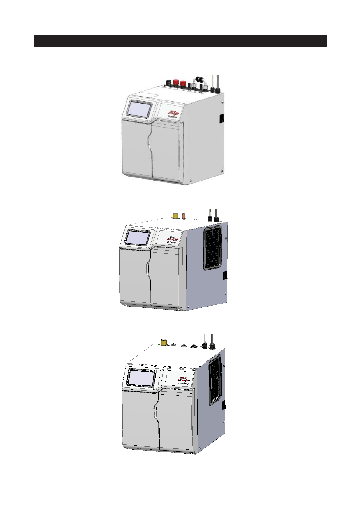
Models
Model BHA
Model CHA
Model CSHA
Page 2 of 28 802149 - BHA; CHA; CSHA -Installation Instructions - 09.2016 - V2.01
Page 3

Index
Specifications
Installation check list ....................................................................................................................4
General Product Features ............................................................................................................5
Important Safety Instructions .......................................................................................................6
Warnings and Regulatory Information ..........................................................................................7
Major components and Accessories ............................................................................................8
Technical Specification ................................................................................................................9
Before Installation and site requirements .....................................................................................9
STEP 1 -
STEP 2 - Check for adequate ventilation
STEP 3 -
STEP 4
Section 4 - Undersink unit installation
Measure and cut all the tap holes before fitting the taps
Section 1 - Tap Installation instructions ......................................................................................10-12
1.1 - Bench top hole size ...................................................................................................11
1.2 - CSHA Tap connections .............................................................................................11
1.3 - BHA & CHA tap connections ....................................................................................12
1.4 - Tap installation ..........................................................................................................13
Section 2 - Ventilation .................................................................................................................14
2.1 - Cut out details ...........................................................................................................15
2.3 - Cut out procedure .....................................................................................................16
Fit the CO2 Gas cylinder (CSHA model)
Section 3 - CO2 Cylinder ............................................................................................................17
3.1 - Connect and secure the CO2 gas cylinder ...............................................................18
- Install the undersink unit
4.1 - Hose fitting ................................................................................................................19
4.2 - Clearances ................................................................................................................19
4.3 - External bypass valve ...............................................................................................20
4.4 - BHA Installation ........................................................................................................21
4.5 - CHA Installation ........................................................................................................22
4.6 - CSHA Installation ......................................................................................................23
STEP 5
Section 5 - Commissioning
- Commission the Celsius
5.1 - CO2 Purge ................................................................................................................24
5.2 - Filter flush .................................................................................................................24-25
5.3 - Boiling Calibration (BHA Model) ...............................................................................25
Trouble Shooting
End of life disposal .......................................................................................................................25
Trouble Shooting Table ................................................................................................................26
Notes ............................................................................................................................................27
Contact details .............................................................................................................................28
802149 - BHA; CHA; CSHA -Installation Instructions - 09.2016 - v2.01 Page 3 of 28
Page 4

Installation checklist
Before Installation:
A. Read the instructions and check if there is adequate space to mount all of the components.
B. Note: Not all fittings are supplied with the appliance kit. Isolation valves are not supplied.
C. Check the mains water pressure is between 172-700kPa for BHA & CHA or 250-700kPa for
CSHA units
D. Check the water quality to determine if extra filtration will be required.
NOTE: This product must be fitted to a potable water supply
E. Check the appliance rating plate and ensure correct power is available for the appliance.
F. Check the under counter cupboard supporting the appliance is adequate for
the total weight of the appliance, when full of water.
Before Commissioning:
1. Check the unit has been installed correctly.
2. Check all plumbing fittings have been tightened.
3. Ensure the outlet and vent pipes are positioned to drain correctly.
4. Ensure there is adequate ventilation.
5. Check all tubes from the undersink unit to the tap, have a constant rise and there are no
sags or kinks in the hoses.
6. Check all electrical connections are correct and there are no loose wires.
Commission: (See section 5)
7. Flush the supply line before connecting.
8. Turn on the water and check for leaks.
9. Flush the filters
10. Purge the CO
11. Where applicable, programme the unit to suit the customer’s requirements.
Page 4 of 28 802149 - BHA; CHA; CSHA -Installation Instructions - 09.2016 - V2.01
2
Page 5
General Product Features
Thank you for purchasing a Zip Celsius. Please read and follow these instructions carefully to ensure safe and
trouble free service. If service is required, please call 1800 638 633
What is the Zip Celsius ?
The Zip Celsius is a conventional flick mixer tap that dispenses, Boiling or Chilled still and Chilled Sparkling
water from the same outlet. The Celsius units are under bench drinking water appliances with a dispensing
tap mounted on a kitchen sink or bench. These units utilise a conventional refrigerant compressor to chill the
water and a CO
gas cylinder to carbonate the chilled water. The Celsius taps will dispense Boiling or Chilled
2
and Chilled Sparkling water using a rotating handle and deliver a mix of Hot and Cold ambient water through
a conventional mixer lever.
The water filter and CO
gas cylinder are disposable items which will require periodic replacement and are
2
covered by a limited OEM warranty.
It is important that the Installation be done safely, correctly and completely, in order to utilise all the benefits
the Celsius can provide.
Usage:
The Zip Celsius is intended for use in residential household and similar applications such as, Rural and urban
residential Kitchens, Hotels, Motels, Bed and Breakfast and other residential type environments
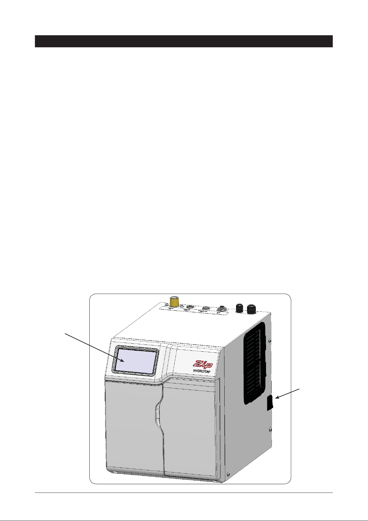
CSHA - under bench unit
Command
centre
ON - OFF
Switch
802149 - BHA; CHA; CSHA -Installation Instructions - 09.2016 - v2.01 Page 5 of 28
Page 6

Important Safety Instructions
This manual contains important safety, Installation instructions for the Zip Celsius.
Safety
This appliance is not intended for use by persons (including children) with reduced physical,
sensory or mental capabilities, or lack of experience and knowledge, unless they have been
given supervision or instruction concerning use of the appliance by a person responsible for
their safety. Children should be supervised to ensure that they do not play with the appliance.
For products sold in Europe, this appliance can be used by children aged from 8 years and above and
persons with reduced physical, sensory or mental capabilities or lack of experience and knowledge if they
have been given supervision or instruction concerning use of the appliance in a safe way and understand
the hazards involved. Children shall not play with the appliance. Cleaning and user maintenance shall not be
made by children without supervision.
Refrigerant
The Zip Celsius unit contains R134A refrigerant under pressure. Maintenance of the refrigeration unit must be
carried out by an accredited service provider or qualified refrigeration technician.
Qualifications
If the power cable is damaged it must be repaired only by a qualified technician. To avoid hazards, all
Installation procedures must be carried out by a suitably qualified tradesperson. The power cable and power
outlet must be in a safe visible position for connection.
Venting
Sometimes steam and / or condensed droplets may discharge through a vent outlet at the tap. If the tap is not
installed using the Font pedestal, ensure the tap body is located so the tap outlet safely dispenses into the
sink bowl area.
Lifting
Take care when lifting the Zip Celsius unit. Some units may exceed safe lifting limits. If you feel this is beyond
your personal capabilities, please seek assistance with the lift. The weights of the units are marked on the
packaging. Do not lift the unit by the front cover or any connections at the top rear of the unit. Refer to the
technical specification for the weight of your product.
Airflow
The ambient operating temperatures, when installed in a cupboard, must be between 5ºC - 35ºC. The
system will operate satisfactorily only if proper air ventilation is provided and only if the recommended air
gaps of 50mm on each side are provided. See section 2 for correct Installation details.
Frost Protection
If this appliance is located where the ambient air temperature could fall below 5ºC when the unit is not in use,
do not turn off the appliance electrically. This safeguard does not offer the same protection to the connecting
pipework and fittings.
ed
Positioning
It is important to ensure the undersink unit is positioned in an accessible area close to the floor level. The unit
must have it’s base mounted in a horizontal position with all inlets and outlets facing up. The Tap must be
located above the undersink unit. See section 4 for details.
Page 6 of 28 802149 - BHA; CHA; CSHA -Installation Instructions - 09.2016 - V2.01
Page 7
Important Safety Instructions
WARNINGS
1.
The Zip Celsius unit must be earthed. The resistance of the earth
connection from each exposed metal part must be less than 1 ohm.
2.
All Installation and service work must be completed by trained and
suitably qualified Tradespeople. Faulty operation due to unqualified
persons working on this product, or any other Zip product may void
warranty coverage.
3.
All Plumbing must comply with AS/NZS3500.
4.
All Electrical must comply with AS/NZS3000
5.
All Plumbing and Electrical connections must be made in accordance
with local regulations.
6.
This product is rated for 230V 50Hz AC operation.
7.
Undersink units must never be located near, or cleaned with water jets.
8.
Zip appliances are not to be exposed to the elements of nature
9.
Due to the process of continuous improvement, Zip Heaters reserves
the right to change details mentioned in this manual, without notice.
CO2 Cylinder Warnings:
•
Pressurised container.
•
Protect from sunlight.
•
Contains gas under pressure, may explode if heated.
•
Do not expose to temperatures exceeding 50˚C.
•
Do not pierce or burn, even after use.
•
Do not refill – non rechargeable
•
Ensure cylinder is empty before disposal.
•
Do not expose to naked flame or any incandescent material.
•
Keep out of reach of children.
•
High concentration of gas may cause asphyxiation.
•
Use only in ventilated areas.
•
Store in an area no less than 38 cubic meters.
•
Use only in an upright position.
•
This bottle must be used with the approved pressure regulator.
•
Avoid shock.
•
Use according to MSDS. (Material Safety Data Sheet).
802149 - BHA; CHA; CSHA -Installation Instructions - 09.2016 - v2.01 Page 7 of 28
Page 8
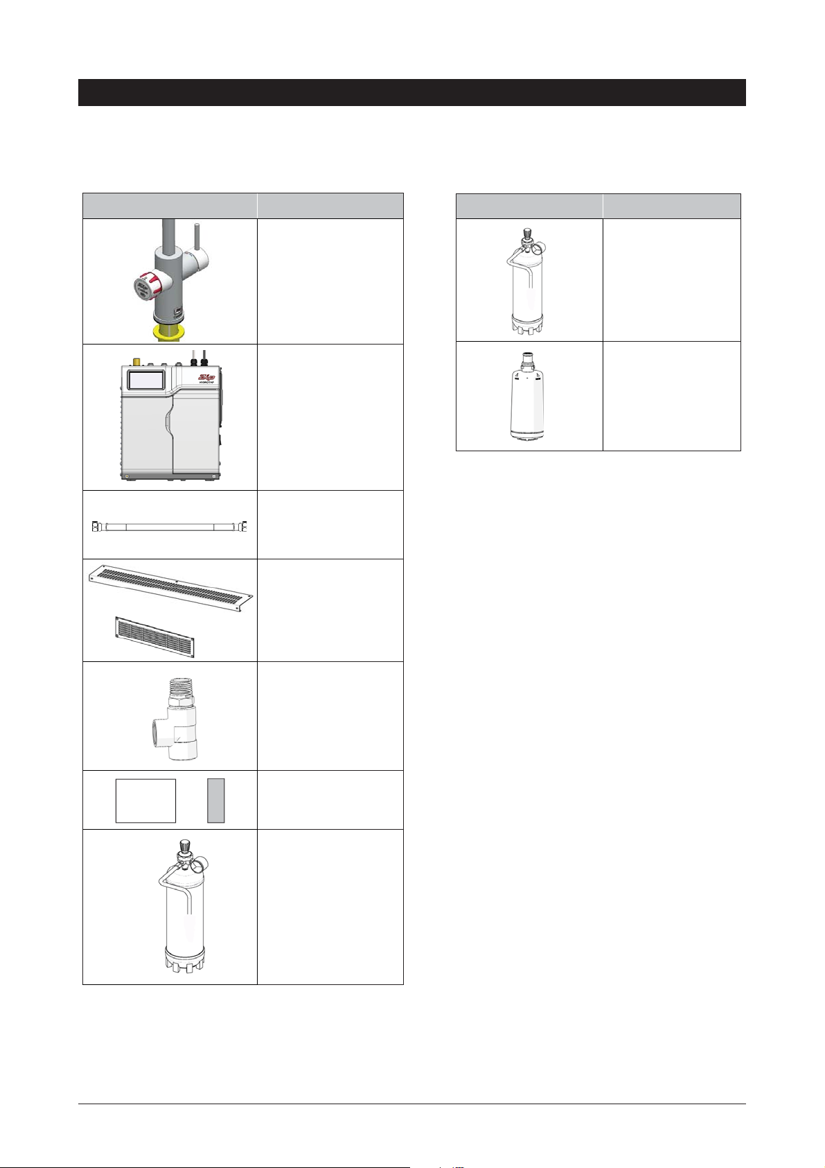
Major components and accessories
Parts supplied Description
1 off
Tap with hoses
1 off
Undersink Unit with
air and water filters
1 off
Mains water
connection hose
Vent Kit
1 x Inlet vent
1 x Outlet vent
9 x Screws
Accessories Description
Replacement CO
Gas Cylinder
Replacement Filter
2
Guide
1 x Tee piece for
ambient water supply
1 x User guide and
1 x Quick start guide
1 off
CO
gas cylinder and
2
regulator assy
Page 8 of 28 802149 - BHA; CHA; CSHA -Installation Instructions - 09.2016 - V2.01
Page 9
Technical Specifications
Residential Models:
BHA = Filtered Boiling water with unfiltered Hot and Cold Ambient water
CHA = Filtered Chilled water with unfiltered Hot and Cold Ambient water
CSHA = Filtered Chilled and Sparkling water with unfiltered Hot and Cold Ambient water
Note: chilled water will continue to be dispensed after the rated capacity has been used, although this
may be at slightly higher temperature.
Product covered by these instructions:
** Add an extra 4 kg
when full of water
GPO's
Required
Chilled Sparkling
BHA 1x10A 1.425 280 x 313 x 335 8
CHA 1x10A 0.125 280 x 392 x 335 20
CSHA 1x10A 0.3 280 x 392 x 335 23
Power
Rating
(kW)
Unit Dimensions
W x D x H
(mm)
**Dry
Weight
(Kg)
Before installing ensure that the following have been
provided at the Installation site:
•
Review all the technical specifications.
•
Ensure the underbench can support the product weight when full of water.
•
Sufficient space in the cupboard to install all of the undersink units in
accordance with these Installation Instructions. Refer to technical specification
for dimensions. Refer to section 3 & 4, for Installation instructions.
•
For Zip Celsius models, a 220-240Vac, 10A GPO will be required.
NOTE: Check all cable and hose lengths against inlet /outlet
positions before proceeding (See section 4 for general layout).
•
A potable water supply connection with isolating valve inside the cupboard
within reach of the braided hoses and positioned so that the connection
point and the stop cock will not be obstructed when the undersink units are
installed.
•
If an external filtration or water softening device is required, then it is
important to allow extra space for these items.
•
A cold water supply with a minimum working pressure of 172kPa for BHA &
CHA or 250kPa for CSHA units and a maximum working pressure of 700kPa
connected via an isolation valve.
•
The appliance must be placed with it’s base in a horizontal position.
IMPORTANT!
not met.
802149 - BHA; CHA; CSHA -Installation Instructions - 09.2016 - v2.01 Page 9 of 28
Do not proceed with the Installation if these requirements are
Page 10
Section 1
Tap Installation
Special Tools Required:
In addition to normal tools, the following will be required:
•
35mm diameter sheet metal hole punch for sink tops. (Not supplied)
•
35mm diameter hole saw for timber bench tops. (Not supplied)
•
42mm AF tube spanner or wrench (Not supplied) for fixing tap assembly.
NOTE: Taps are available with ARC or CUBE neck options.
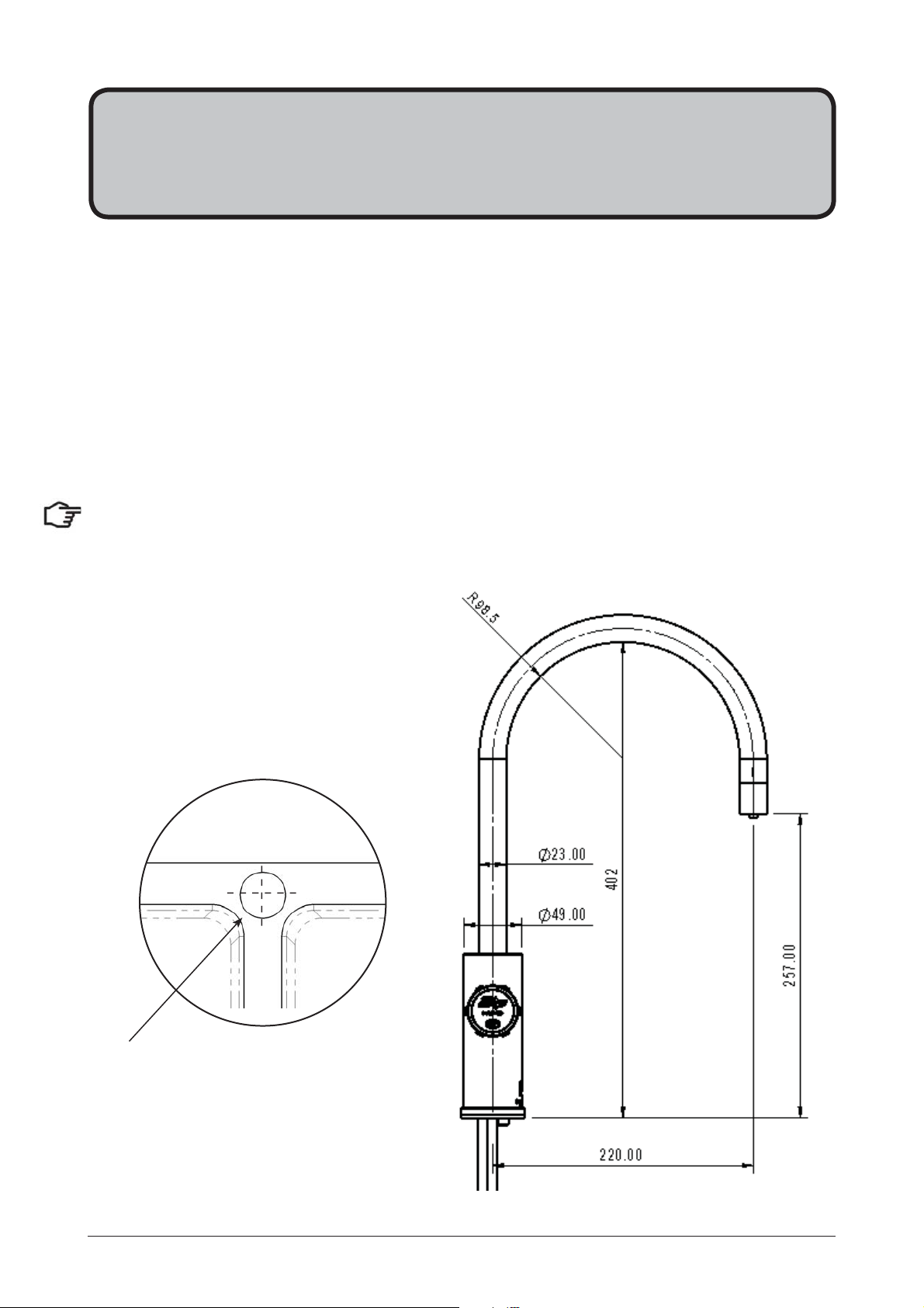
Hole positioning:
Position the tap such that it dispenses
into the sink bowl.
Double Bowl
35mm hole
Page 10 of 28 802149 - BHA; CHA; CSHA -Installation Instructions - 09.2016 - V2.01
Page 11

CSHA Tap connections
1.1
Ø35mm
BENCH TOP
Cut a 35mm hole in the bench / sink top.
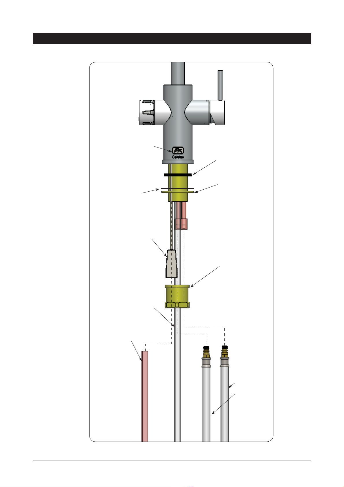
Chilled Sparkling Tap components
1.2
Note: Trim all plastic
tubes to minimise any
dead leg of water.
RUBBER
Washer
USB
PLUG
HOT & COLD
BRAIDED
HOSES
BLACK RUBBER
Seal
BRASS
WASHER
BRASS
NUT
JG
Y-PIECE
CHILLED
TUBE
SPARKLING
TUBE
802149 - BHA; CHA; CSHA -Installation Instructions - 09.2016 - v2.01 Page 11 of 28
Page 12
1.3
BHA and CHA Tap connections
Boiling
model Vent
outlet
RUBBER
Washer
BLACK RUBBER
SEAL
BRASS
WASHER
BOILING
or
CHILLED
TUBE
USB
PLUG
BRASS
NUT
VENT
TUBE
HOT & COLD
BRAIDED
HOSES
Page 12 of 28 802149 - BHA; CHA; CSHA -Installation Instructions - 09.2016 - V2.01
Page 13
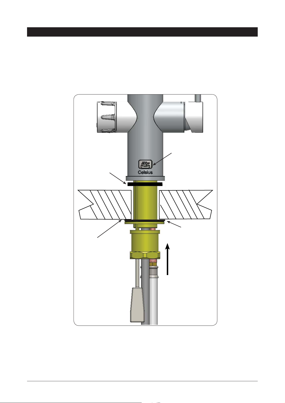
1.4
Tap Installation
•
Pass all the hoses, tubes and USB lead through the 35mm hole.
•
Ensure the black rubber seal is correctly positioned to give a water tight seal
Boiling
model Vent
BLACK
RUBBER
SEAL
outlet
RUBBER
WASHER
35mm HOLE
IN BENCH
TOP
FIT THE
RUBBER WASHER,
BRASS WASHER,
AND LARGE NUT
Secure the rubber & brass washers and large nut from inside the cupboard space, as shown above.
802149 - BHA; CHA; CSHA -Installation Instructions - 09.2016 - v2.01 Page 13 of 28
Page 14

Section 2
Ventilation
When installing air flow ducts, the following tools will be required:
•
Jigsaw and
•
Keyhole or Wall Board saw.
2.1
Ventilation for All Models
Proper air circulation must be provided for all Boiling and Chilled models. The system will operate correctly
only if the recommended air gaps are achieved during Installation. The minimum requirement is for a 50mm air
gap either side and 300mm above of the undersink unit.
It is important that the 4mm door buffers (For all installations ) are fitted to the inside edge of the
cupboard door to allow suficient air circulation inside the cupboard. (See the diagram below). Under normal
circumstances, these buffers are sufficient for residential models.
IMPORTANT:
See section 4 for clearances.
4mm Buffer
Pad to ensure
ventilation gap
Min 300mm
Page 14 of 28 802149 - BHA; CHA; CSHA -Installation Instructions - 09.2016 - V2.01
Page 15

Ventilation
2.2
The following instructions are critical if there is insufficient cupboard air
circulation.
If the air flow, using the silicon door buffers, is insufficient, it will be necessary to fit a standard vent kit, which
ensures heat dissipation through natural convection via installed vents.
For high use applications, where the cupboard space temperature is near 35°C, or higher, the inlet vent
(See Item B below) and silicon buffers, need to be fitted. If the airflow is still insufficient to maintain normal
operating temperatures then the door outlet vent (See item D below) will need to be fitted.
Alternatively a fan kit may be installed, using the AUX din plug on the right hand side of the appliance
(Contact your local service centre for availability).
Note: The vent kit has to be installed in a way that allows air to be drawn in from the bottom of the cupboard
and expelled through the top of the cupboard. Therefore placement of the outlet vent should be towards the
top of the door or on the side of the cupboard.
Airflow through the cupboard
Warm air
OUT
Door outlet vent
Cutout details
1.
Drill four pilot holes
12mm dia.
2.
Finish the cutout using
a jig saw and keyhole
or Wall Board saw
D
Air inlet vent position
Cool air IN
B
802149 - BHA; CHA; CSHA -Installation Instructions - 09.2016 - v2.01 Page 15 of 28
Page 16

Ventilation
2.3
Typical Cut out procedure for
1.
Mark out and cut the air inlet and door outlet holes as shown
2.
Ensure the air inlet vent and air outlet vent are positioned at opposite ends
of the same cupboard space.
3.
Fit the inlet vent, as shown and secure with 5 screws
4.
If required, fit the outlet vent, as shown in the hottest part (top) of the
cupboard and secure with 4 screws
B
D
B
Air inlet vent
Cutout deatils
Page 16 of 28 802149 - BHA; CHA; CSHA -Installation Instructions - 09.2016 - V2.01
Page 17

Section 3
CSHA - CO
Cylinder
2
3.1
Secure the gas bottle supplied to a suitable wall, within 1 metre of the unit, in an upright position. This is
done by screwing the metal plate holding the Hook-and-loop strap to a cupboard wall, 200mm above the floor
or base of the cupboard. Make sure the gas bottle can stand before securing to the wall. Due to regulatory
requirements the gas bottle must be stored securely and in an upright position.
3.2
Make sure the regulator knob is turned fully anti-clockwise to the end-stop before fitting. Fit the regulator to
the gas bottle. Be aware that some CO
excess gas leakage, promptly screw the regulator on to the bottle.
3.3
Connect the braided gas hose to the top of the undersink unit via the John Guest fitting marked ‘Gas IN’
Then connect the threaded end to the regulator, taking care not to lose the plastic olive located inside the
threaded nut. To turn the gas ON, rotate the regulator knob clockwise and adjust to 2.7-3.0 bar (270-300kPa).
The arrow should sit in the green section of the regulator gauge; it should not fall in the red or yellow
sections.
Secure the cylinder mounting
Connect the regulator:
may be discharged from the connection during assembly. To avoid
2
Connect the gas hose:
3.4
Test for gas leaks:
Using soapy water perform a leak test. Apply the soapy water to the gas connections using a sponge. If any
bubbles appear and grow, there is a gas leak at the connection. Clean away the soapy residue and tighten
or refit the leaking connection. Make sure the regulator is turned off when tightening or refitting the leaking
connection.
Refit the gas bottle to the Hook-and-loop strap and secure the bottle in an upright position.
NOTE:
normal operating pressure of 2.7-3.0 bar (270-300kPa) be exceeded.
Connect the unit to the mains power supply.
WARNING:
A gas cylinder containing 1kg of CO2 should be installed in a well ventilated area or an area no less than
38m
If more than 1 gas cylinder containing 1kg of CO
ventilated area should be in proportion to the number of gas cylinders stored in that location.
A ventilated area is a non-enclosed area which could include the kitchen, living room etc.
Care must be taken when working with high pressure carbon dioxide, and in no cases should the
3
.
is present within the same location, the recommended
2
See gas bottle and MSDS sheet for complete list of warnings.
802149 - BHA; CHA; CSHA -Installation Instructions - 09.2016 - v2.01 Page 17 of 28
Page 18

CO2 Connections
CO2 pressure set zone -2.7-3.0 bar
After replacing a bottle or after making a
gas connection:
Stage1:
1.
Turn the gas OFF
2.
Using soapy water applied with a sponge, or with
a brush, cover all of the gas joints with a liberal
amount of soap suds.
Stage 2:
1.
Turn ON the gas
2.
Inspect the joint for leaks
3.
If any bubbles appear, the joint
will need to be resealed.
Faulty seal joint
Page 18 of 28 802149 - BHA; CHA; CSHA -Installation Instructions - 09.2016 - V2.01
Page 19
Section 4
Undersink Unit Installation
4.1 Hose fitting
Install the mains water braided hose to the undersink unit before locating the unit in place.
Note: The connection hoses supplied with the tap head assembly and cold inlet CANNOT be lengthened.
Note: Insulate the Blue and White tubes after trimming to length
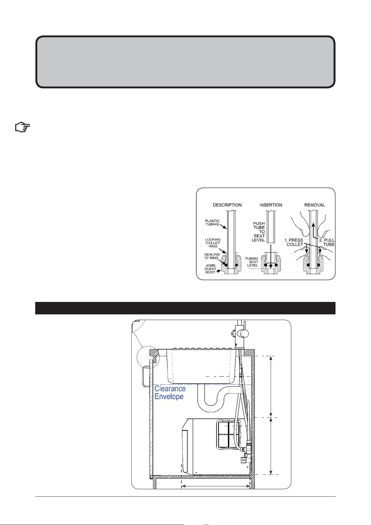
John Guest fittings (Insertion and removal)
Be careful when cutting the poly tube so that there are no rough edges and that the tube is not distorted.
1.
Use a sharp knife to ensure the tube has a clean,
straight edge. Do not cut at an angle.
2.
Remove any swarf or unwanted material.
3.
Push the tube into the John Guest fitting making
sure all connections to the John Guest fittings are
pushed in past the “O”ring to full depth, at least
15-16mm.
4.
Check for a good joint by pulling back on the tube.
If the tube comes out, of the fitting, repeat the
above step.
5.
To remove the tube, press the collet into the fitting and at the same time pull back on the tube.
Common kitchen layout
4.2
Clearances
335mm Min 300mm
392mm
802149 - BHA; CHA; CSHA -Installation Instructions - 09.2016 - v2.01 Page 19 of 28
Page 20
%
5RWDWH
RQO\
$
5RWDWH
RQO\
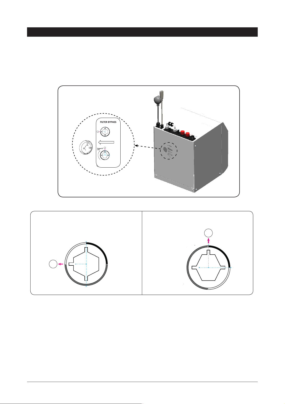
BHA Installation
NO EXTERNAL
FILTER INSTALLED
SELECT POSITION A
EXTERNAL
FILTER INSTALLED
SELECT POSITION B
B
1
2
3
4
A
1
2
3
4
PN: 801231
Note:
4.3
Before you install a unit, determine whether a water softener or an external filter is required.
E
xternal Bypass Valve
The diverter bypass valve allows the user to choose to have the boiling feed water bypass the internal filter
and only be filtered by the external filtration. This diverter valve is located at the rear panel of the Zip HydroTap
undersink unit, see the image below.
Check the table below to determine which filter bypass position you need for your product.
If no external fi lter is installed, select position A
If an external filter is installed, select position B
Page 20 of 28 802149 - BHA; CHA; CSHA -Installation Instructions - 09.2016 - V2.01
Page 21
Installation Instructions
Note:
All
silicon tubes
must be cut to
size. They must
have a constant
fall back to the
unit.
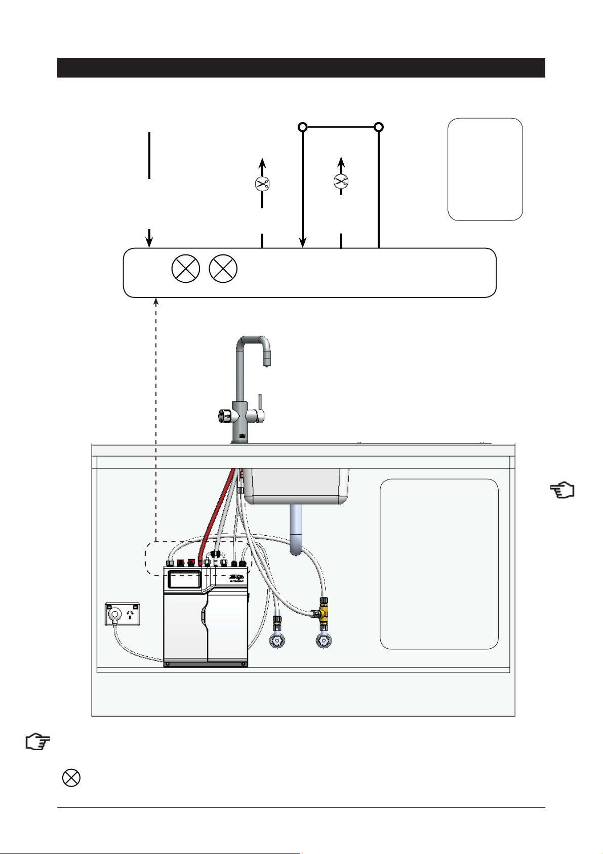
4.4
Model BHA
MAINS INMIXER
BRAIDED
OUT
RED
MIXER INBOILING
OUT
CLEAR
BYP ASS INVENT BYPASS
OUT
USB
Note:
silicon tubes
must be cut to
size. They must
have a constant
fall back to the
POWER
CORD
unit.
All
Note:
isolation valve (Not supplied), to the mixer tap. (See diagrams)
The Celsius tap requires theTee piece, as supplied, to be fi tted in the cold water supply line, from the
: Not required for standard BHA HydroTap models.
Note:
- Mains hose length is
750mm
- Plug and Cord length is
1800mm
Position the undersink
unit close to the Celsius
tap and according to the
hose and cord lengths
supplied
802149 - BHA; CHA; CSHA -Installation Instructions - 09.2016 - v2.01 Page 21 of 28
Page 22

4.5
Note:
All
silicon tubes
must be cut to
size. They must
have a constant
fall back to the
unit.
Model
Installation Instructions
CHA
BRAIDED
MAINS
IN
BLUE
CHILLED
OUTLET
USB
POWER
CORD
Note:
silicon tubes
must be cut to
size. They must
have a constant
fall back to the
unit.
All
Note:
isolation valve (Not supplied), to the mixer tap. (See diagrams)
The Celsius tap requires theTee piece, as supplied, to be fi tted in the cold water supply line, from the
Note:
- Mains hose length is
750mm
- Plug and Cord length is
1800mm
Position the undersink
unit close to the Celsius
tap and according to the
hose and cord lengths
supplied
Page 22 of 28 802149 - BHA; CHA; CSHA -Installation Instructions - 09.2016 - V2.01
Page 23

4.6
Note:
Trim all plastic
tubed to mini-
mise any dead
leg of water
Model
CSHA
Installation Instructions
Note:
Trim all plastic
tubed to mini-
mise any dead
leg of water
BRAIDED
MAINS
IN
BLUE
CHILLED
OUTLET
WHITE
SPARKLING
OUTLET
BRAIDED
CO2
IN
POWER
USB
CORD
Note:
- Mains hose length is
750mm
- Plug and Cord length is
1800mm
Position the undersink
unit close to the Celsius
tap and according to the
hose and cord lengths
supplied
280mm
Note:
isolation valve (Not supplied), to the mixer tap. (See diagrams)
802149 - BHA; CHA; CSHA -Installation Instructions - 09.2016 - v2.01 Page 23 of 28
The Celsius tap require the Tee piece, as supplied, to be fi tted in the cold water supply line, from the
Page 24

Section 5
Commissioning
The Celsius is now ready to be commissioned.
•
Turn ON the water and check for any leaks.
•
Turn the power ON at the GPO and at the side of the undersink unit.
•
Familiarise yourself with the operation of the Tap, in preparation for use (See User Guide).
•
Select the language option from the view screen.
•
Follow the Installation instructions below (and review Section C of the User Guide).
•
After commissioning, the system may be customised by selecting further options in Section G Settings, within the User Guide.
5.1 - CO
NOTE:
at first commissioning, the system will select the CO2 Purge screen automatically.
Purge (Model CSHA)
2
1.
Press the [START] button to commence the purging
process.
2.
Purge for 10 seconds and ensure all water has stopped
flowing through the tap. (You will hear the CO
escaping from the tap).
3.
Press the [Stop] button.
4.
Press [Next] for the filter flush screen
gas
2
5.2 - Filter Flush (Model BHA; CHA & CSHA)
Have a 10L bucket or similar container (not supplied) at the ready to hold the water that will be ejected while
the Filter Flush Mode is in operation. Open the filter access door on the front of the unit and the filter cartridge
will be exposed. Located to the rear RHS of the cartridge is a flush line, approx 600mm long and the flush
line stop cock. Place the valve end of the flush line into the bucket or container (not supplied).
NOTE: the flush line may be extended using 1/4” JG tube (Not supplied)
G4 Celsius Filter Flush Menu
OPEN Position
ON
Stop cock
operation
CLOSED Position
Page 24 of 28 802149 - BHA; CHA; CSHA -Installation Instructions - 09.2016 - V2.01
OFF
Page 25

Commissioning
T
1.
Press [Start] [Stop] buttons to start and stop the filter
flush.
2.
Turn the flush line stop cock ON (See diagram).
3.
Press [Start] and allow at least 10 litres of water (1 x Std
Bucket) to flush through the filter.
4.
For convenience, the product details will be displayed in
the screen.
5.
Once the filter flush is finished, Turn the stop cock OFF
then press [Stop] to end filter flush mode.
NOTE: For any subsequent fi lter changes or any operational procedures, please refer to the Celsius user
guide, located inside the fi lter housing access door.
5.3 - Boiling Calibration (Model BHA)
The Zip HydroTap is equipped with a self-calibrating program to adjust for altitude. On start up, the controls
take the system through a calibration process. Once this mode is complet the system reverts back to normal
operation.
Boiling
Boiling Water
97.5
Steam Vent
53.0
EL
03:01 PM, TUE 12, Feb 2013
Calibrate
To start press
Calibrate
button
•
Press the calibration button and the system will
commence the Boiling calibration procedure. This
will take aprox 5-6 minutes.
End of Life Disposal
In order to help preserve our environment we ask that you dispose of this product correctly. Please contact
your local city council for collection centre details.
802149 - BHA; CHA; CSHA -Installation Instructions - 09.2016 - v2.01 Page 25 of 28
Page 26

Trouble Shooting
System Fault
Possible Cause Solutions
Message
Power board fault Electrical disruption Check power supply and all fuses
Interface fault Internal fault Call Zip Service
Level board fault Internal fault Call Zip Service
Condenser screen blocked Blocked Air filter Remove blockage / Clean filter / check user guide
Water leak, Isolate mains Water leak Turn off mains water supply / Call for service
Compressor over-run Compressor too Hot Check ventilation
Water supply failed No water Check water supply is turned ON
Hot sensor Open Internal fault Call Zip Service
Hot sensor Closed Internal fault Call Zip Service
Cold sensor Open Internal fault Call Zip Service
Cold sensor Closed Internal fault Call Zip Service
Flood sensor Open Internal fault Call Zip Service
Condenser sensor Closed Internal fault Check Ventilation / Call Zip Service
Condenser sensor Open Internal fault Check ventilation / Call Zip service
Heater fuse / driver fault Internal fault Call Zip Service
Heater driver fault No hot water Call Zip Service
Compressor driver fault No chilled water Call Zip Service
Hot sensor degraded Internal fault Call Zip Service
Condenser overtemp. Blocked air filter Remove blockage / Clean filter / check user guide
A DC Pump is faulty Internal fault Call Zip Service
Steam is too cool Internal fault Call Zip Service
Steam sensor Open Internal fault Call Zip Service
Steam sensor Closed Internal fault Call Zip Service
Over Steamed Internal fault Call Zip Service
Hot tank overfilled Internal fault Call Zip Service
Comp Fuse/Driver Fault Internal fault Call Zip Service
Hot tank under filled Low water pressure Check water supply
Boil dry protection Safety activated Turn OFF / On power to reset
Flash Mem corrupted Internal fault Call Zip Service
Flow Sensor Fault Internal fault Call Zip Service
Call an electrician, a plumber, or Zip for a free call in Australia on 1800-638-633 for assistance, service, spare
parts or enquiries.
Page 26 of 28 802149 - BHA; CHA; CSHA -Installation Instructions - 09.2016 - V2.01
Page 27

Notes
802149 - BHA; CHA; CSHA -Installation Instructions - 09.2016 - v2.01 Page 27 of 28
Page 28

Head Office
Zip Heaters (Aust) Pty. Ltd.
ABN: 46 000 578 727
67 Allingham Street
Condell Park NSW 2200
Postal: Locked Bag 80
Bankstown 1885 Australia
Contact Details
Website: www.zipindustries.com
Facsimile: (02) 9796 3858
Telephone: (02) 9796 3100
Sales & Service.
Free Call: 1 800 63 86 33
Customer Care.
Free Call: 1 800 42 43 44
As Zip policy is one of continuous product improvement, changes to
specifications may be made without prior notice. Images in this booklet have
been modified and may not be true representations of the finished goods.
The terms “Zip” and “Celsius” are registered trade marks of Zip Heaters (Aust)
Pty Ltd.
Zip products described in this publication are manufactured under one or more
of the following patents: AU675601, AU637412, AU635979, GB0422305,
GB2065848, US4354049, US5103859, US5099825 and SA2006/08043. Other
patents are in force and patent applications are pending.
WMK25927
AS/NZS 3718
WMKA00099
AS 3498
Page 28 of 28 802149 - BHA; CHA; CSHA -Installation Instructions - 09.2016 - V2.01
 Loading...