

Zip HydroTap G4 Elite, HydroTap G4 Arc, HydroTap G4 Classic All-in-One, HydroTap G4 Celsius All-in-One, HydroTap G4 Celsius Installation Instructions Manual
...Page 1
Installation instructions
Zip
®
HydroTap G4
Tap range.
Model number:
(See table of contents for specific models).
Installation instructions
803341 V3.00 June 2019 - Zip G4 tap range
Australia Ph: 1800 460 222 , UK Tel: 0345 6 005 005 email: service@zipindustries .co.uk
Technical support
1
Page 2
Tap options
The G4 series offers a range of interchangeable taps to suit the customer's needs.
Classic range
These standalone taps offer instant boiling, chilled
and sparkling water* and are directly compatible
with the G4 Command-Centre.
Arc / Cube range
Elite range
Mixer range
Classic All-in-One
The mains and vented mixer tap range may be
used in conjunction with any of the above to
provide mixed hot and cold water for sanitary
use*.
The All-in-One taps may be used as alternatives to
the above HydroTap and mixer tap combinations*.
Celsius All-in-One
The Celsius range offer instant boiling, chilled
and sparkling / boiling and chilled / boiling and
ambient / chilled and sparkling / chilled or boiling*
water together with the an integral mixer to
provide mixed hot and cold water from the mains.
Celsius range
Installation instructions
02
803341 V3.00 June 2019 - Zip G4 tap range
*Dependant upon model purchased.
Technical support
Australia Ph: 1800 460 222 , UK Tel: 0345 6 005 005 email: service@zipindustries .co.uk
Page 3

Table of contents
Tap options .............................................................................................................................................2
Generic installation instructions .............................................................................................................4
Min / Max water supply pressure requirements .....................................................................................4
Special tool requirements .......................................................................................................................4
Hole & tap positioning ............................................................................................................................5
Clearance envelope .................................................................................................................................6
Command Centre connection table .......................................................................................................6
Tap installation
Section 1 - Classic and Elite HydroTap G4 installation .............................................................................7
Section 2 - Arc / Cube HydroTap G4 installation ....................................................................................8
Section 3 - Vented Classic Mixer tap installation ....................................................................................11
Section 4 - Mains Arc & Cube Mixer tap installation ...............................................................................12
Section 5 - Vented Arc & Cube Mixer tap installation .............................................................................13
Section 6 - Mains All-in-One tap installation ..........................................................................................15
Section 7 - Vented All-in-One tap installation ........................................................................................18
Section 8 - Mains Celsius tap installation ................................................................................................21
Section 9 - Mains All-in-One Celsius Arc tap installation ........................................................................24
Product information
End of life disposal ..................................................................................................................................27
Contact details ........................................................................................................................................28
Installation instructions
803341 V3.00 June 2019 - Zip G4 tap range
Australia Ph: 1800 460 222 , UK Tel: 0345 6 005 005 email: service@zipindustries .co.uk
Technical support
03
Page 4
Generic installation instructions
!
!
Elite
Classic Classic
HydroTaps All in One taps Mixer taps
Arc / Cube
All-in-
One
Celsius
All-in-One
Celsius Arc
Arc Cube
Using these instructions
These instructions are provided primarily to demonstrate how to install HydroTap
G4 taps
and do not provide sufficient information to install and commission complete HydroTap G4
systems.
Please refer to all safety and installation requirements detailed in the Quick start guide
provided with the Command-Centre, and Command-Centre installation instructions found
online prior to any change to the complete system.
Before commencing the installation, download & read the Command Centre
installation instruction manual, which can be found online at:
(Australia) www.zipwater.com
(UK) www.zipwater.co.uk
Min / Max water supply pressure requirements
HydroTaps and Mains All-in-One & Celsius taps sparkling models.............0.30 MPa (3.0 bar) - 0.7 MPa (7.0 bar)
HydroTaps and Mains All-in-One & Celsius taps non-sparkling models........0.17 MPa (1.7 bar) - 0.5 MPa (5.0bar)
Vented All-in-One sparkling models............................................................0.25 MPa (2.5 bar) - 0.5 MPa (5.0 bar)
Mixer taps and Vented All-in-One non-sparkling model taps.....................0.25 MPa (2.5 bar) - 0.5 MPa (5.0 bar)
Be aware of the risks of hazards which could cause harm when using tools.
Assess the risks before starting the installation.
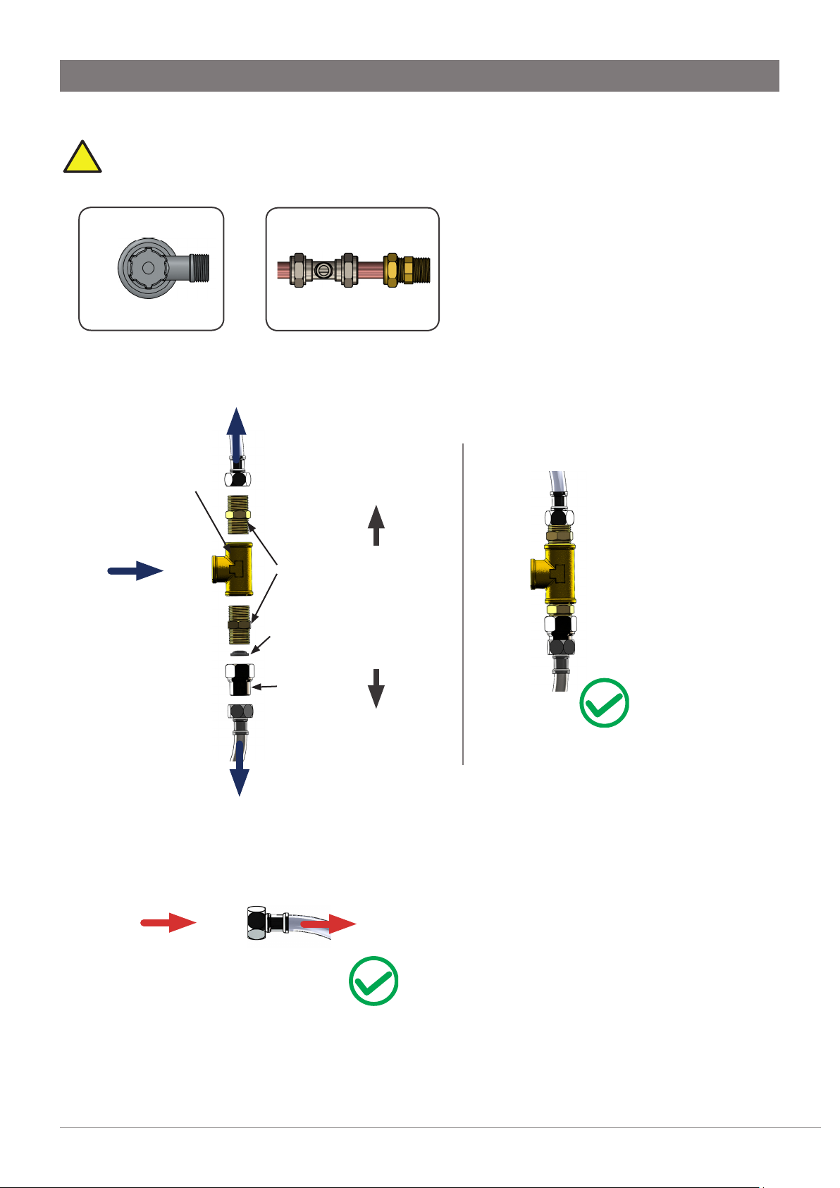
Tap installation special tool requirements
(or equivalent equipment) will be required.
For the HydroTap G4, Celsius and mixer taps (for All-in-One Celsius Arc see below).
• 35mm diameter sheet metal hole punch for sinks (not supplied).
• 35mm diameter hole saw for worktops (not supplied).
• Nut runner tube spanner (supplied for all but Celsius & mixer taps) for fixing the tap assembly.
For the All-in-One tap & All-in-One Celsius Arc.
• 50mm diameter sheet metal hole punch for sinks (not supplied).
• 50mm diameter hole saw for worktops (not supplied).
• Nut runner tube spanner (not supplied for All-in-One Celsius Arc) for fixing tap assembly.
In addition to normal tools, the following
Font installation special tool requirements
• Hole saw or equivalent to suit surface being cut. Ø140m for Arc / Cube and Ø108mm for Classic and Elite.
Installation instructions
04
803341 V3.00 June 2019 - Zip G4 tap range
Australia Ph: 1800 460 222 , UK Tel: 0345 6 005 005 email: service@zipindustries .co.uk
Technical support
Page 5
Generic installation instructions
!
Hole positioning
• Position the tap such that it dispenses into the sink bowl with ample clearance for a cup or tea pot.
Alternatively, the tap could be mounted away from the sink using a Zip Font, available as an accessory.
Tap positioning
Ensure that taps are positioned to minimise the risks of scalding by dispensing
boiling water while using the mixer tap.
Tap
Elite 116
HydroTap Classic 116
HydroTap Arc/Cube 171 (-174 extended)
All-in-One 211
Celsius All-in-One
Arc
Celsius - Arc/Cube 220
Mixer - Arc 220
Mixer - Classic 270
Mixer - Cube 220
Recommended
dispensing
distance (mm)
220
Note
• Celsius, All-in-One and mixer taps have spouts that swivel.
• All images are for illustrative purposes, to aid understanding
of the system configuration, and are not prescriptive of tap
positioning.
• Ensure that the taps are mounted in a position that allows the
water to safely drain to waste throughout the positional range.
116
125
Installation instructions
803341 V3.00 June 2019 - Zip G4 tap range
225 with extension
HydroTap G4 Classic
Technical support
Australia Ph: 1800 460 222 , UK Tel: 0345 6 005 005 email: service@zipindustries .co.uk
05
Page 6

Generic installation instructions
Clearance envelope
• See adjacent diagram.
• A clearance envelope around all Command-Centres must be
provided to allow adequate ventilation for the safe and effective
use of the HydroTap G4 system.
• The tap must have adequate clearance to correctly dress tubes
and hoses without kink or sagging.
• Allow space for the threaded boss and the connection pipes.
Command Centre connection table - for reference
535mm
Clearance
envelope
min. 300mm
335mm
All plastic pipes / silicone tubes must be trimmed to size. They must have a constant fall to the CommandCentre.
The connection tubes supplied with the tap head assembly CANNOT be lengthened.
Mains In Mains water supply. Wholesome (cat 1).
Mains power IEC power lead, 230V AC 50Hz 13A socket.
USB
Connect to the Tap—make sure they click together and are secured up off
the floor of the cupboard.
CO2 IN Connect the 1/4’ connection from the CO2 cylinder.
Boiling out
Chilled out
Vent
Sparkling out
Bypass in
Bypass out
Cut to length Red hose from tap. No kinks, bends or loops. Must fall from tap
directly to Command Centre.
Connect the JG 1/4’ pipe to this push fit outlet. There is another push fit JG
fitting for the tap.
Cut to length clear hose from tap. No kinks, bends or loops. Must fall from
tap directly to Command Centre.
Connect a piece of JG 1/4’ pipe to this outlet. Fit the carbonation valve to the
pipe, then connect valve to tap.
Only used for Booster (supplied with 240/175 models) & scale filter. Braided
hose from Booster outlet (or scale filter).
Only used for Booster (supplied with 240/175 models) & scale filter. Braided
hose from Booster inlet (or scale filter).
Only used when supplied with a special 3 hose mixer tap from Zip. Leave the
Mixer in
red dust caps on if not used.
If using a mixer tap connect to the blue marked braided hose from mixer tap.
Only used when supplied with a special 3 hose mixer tap from Zip. Leave the
Mixer out
red dust caps on if not used.
If using a mixer tap connect to the red marked braided hose from mixer tap.
Cut hoses to length, no clamps are required on silicone hoses.
Installation instructions
06
803341 V3.00 June 2019 - Zip G4 tap range
Australia Ph: 1800 460 222 , UK Tel: 0345 6 005 005 email: service@zipindustries .co.uk
Technical support
Page 7
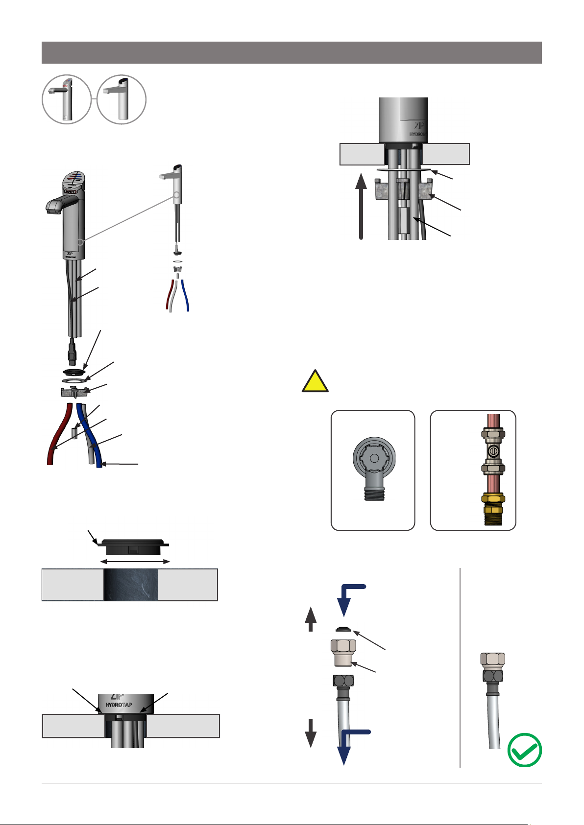
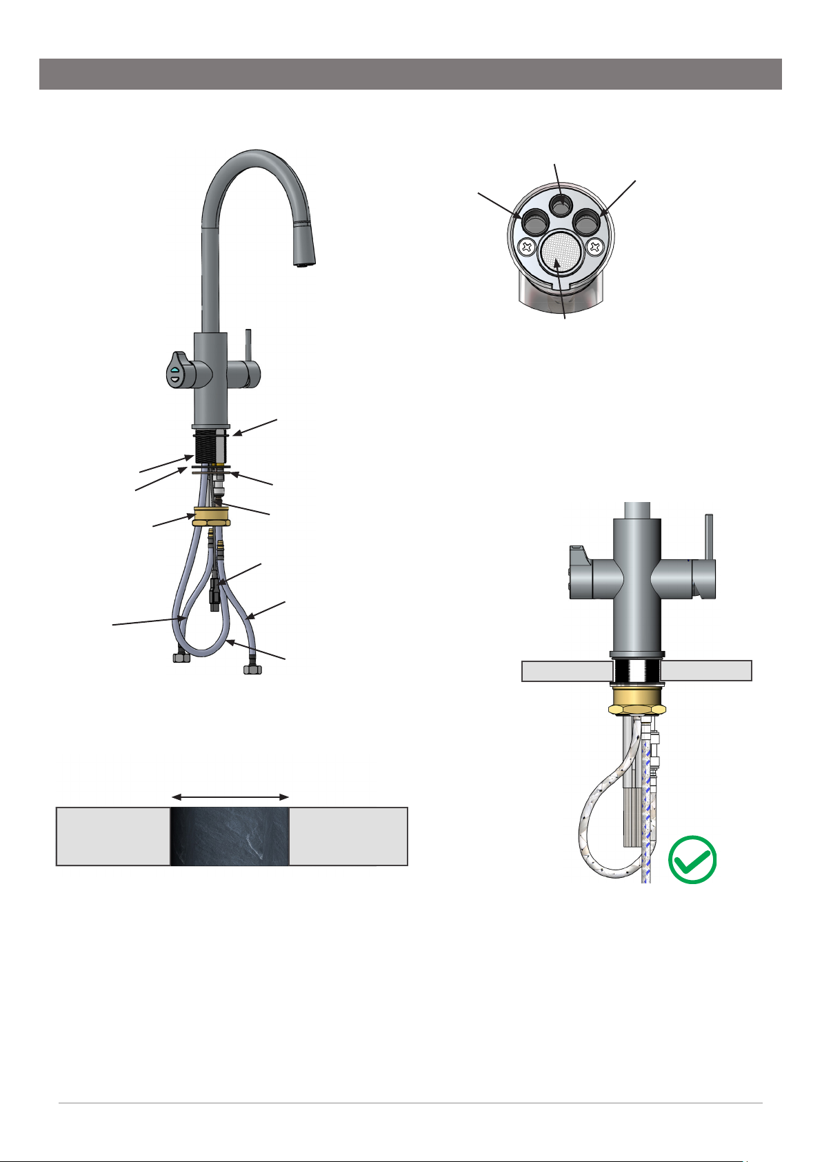
EliteClassic
!
1.1 Configure the tap
All thread rod
USB lead
Black plastic
spacer
Stainless steel
spacer
Spider
clamp
Nut
Red boiling pipe
Clear vent pipe
(boiling models)
Blue chilled pipe
(chilled models)
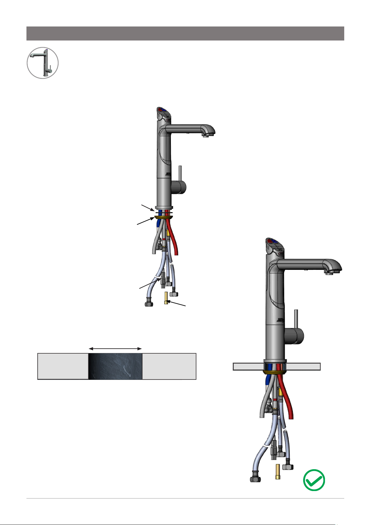
SECTION 1 Classic & Elite HydroTap G4 installation
1.4 Secure the tap
• Fit the stainless steel washer & spider clamp.
• Secure with nut.
• Feed each of the tubes and USB cable evenly
in between the legs of the spider clamp during
installation.
1.5 Connect the water supply (detail shown,
assembled and disassembled)
Note correct filter orientation. Valves and
fittings must be sealed with PTFE tape.
Australia
Stainless steel
washer
Spider clamp
Nut
UK
1.2 Cut the hole & fit the spacer
• Apply a light smearing of silicone sealant on the
underside of the spacer to ensure a watertight fit.
Ø35mm
• Cut a Ø35mm hole in the worktop / sink.
Note Make sure the tap location will allow the tap
spout to drain into the sink.
1.3 Mount the tap
Ø35mm hole
• Pass the tubes and USB cable through
the Ø35mm hole.
Black
plastic spacer
Isolation valve
1/2” BSP
(G 1/2)
- 1/2” BSP
(G 1/2)
Ambient mains water supply
Incoming mains
ambient water
supply
via Isolation valve
(not supplied)
Filter
(supplied)
Male - Female
adaptor
(supplied)
15mm
Connect together
Braided hose
to Command
-Centre
(supplied)
Installation instructions
803341 V3.00 June 2019 - Zip G4 tap range
Australia Ph: 1800 460 222 , UK Tel: 0345 6 005 005 email: service@zipindustries .co.uk
Technical support
07
Page 8
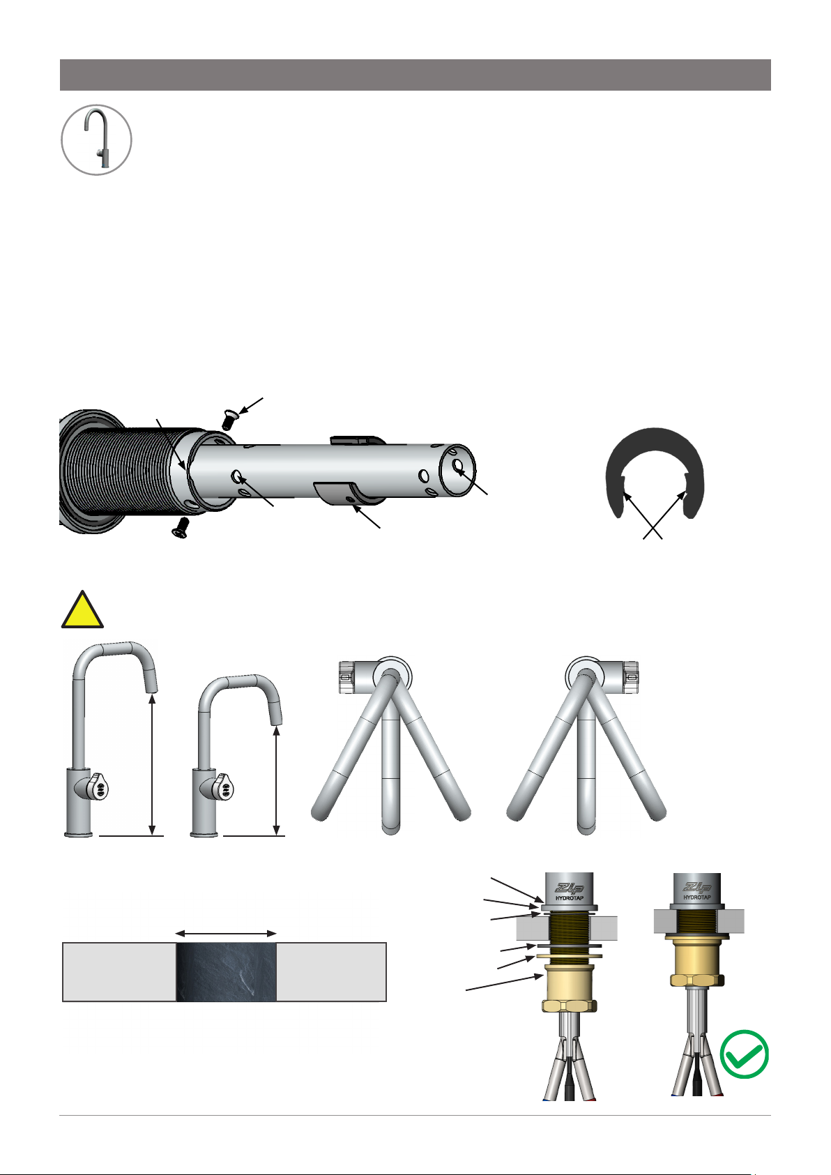
!
SECTION 2 Arc & Cube HydroTap installation
The Arc / Cube have spouts that may be fixed in 1 of 6 angular positions and 1 of 2 height
positions. The spout is fixed and does not swivel.
Arc / Cube
2.1 Configure the tap (see diagram below)
• Remove spout locating screws, lower spout to expose the plastic spring clip.
• To reposition spout, prise open spring clip.
• Slide spring clip up/down to engage selected holes.
• Ensure dimples engage simultaneously with the two selected holes.
• Raise the spout (ensure USB lead fits in undercut and open ends of the clip).
• Align clip with locating holes, & refit the 2 x locating screws.
Undercut
for USB
Spout locating
screws
Lower locating
positions
Upper locating
positions
Spring clip
2.2 Adjust the height & angle (fixed position options, see below)
Scalding risk, Position *A should not be selected with boiling water models.
225mm
175mm
Spring clip
Dimples
2.3 Cut the hole & mount the tap
• Cut a Ø35mm hole in the worktop / sink.
Ø35mm
• Slide o-rings in place.
• Mount tap in position on Ø35mm hole.
• Slide lower rubber washer & metal washer over
threaded boss, tighten the tap nut to secure in place.
• Do not over tighten.
Installation instructions
08
803341 V3.00 June 2019 - Zip G4 tap range
*A
*A
Upper o-ring
Base ring
Lower o-ring
Rubber washer
Metal washer
Nut
Technical support
Australia Ph: 1800 460 222 , UK Tel: 0345 6 005 005 email: service@zipindustries .co.uk
Page 9

SECTION 2 Arc & Cube HydroTap installation
2.4 Fit the tube kit (The L/H & R/H positions of the three way silicone tube are interchangeable) refer to
instruction supplied with the tube kit, and the configuration diagrams below .
Boiling, chilled
& sparkling
Red
Silicone
Vent connector
Blue / White
LLDPE
Red
Silicone
Boiling &
chilled
Clear
Silicone
Blue
Silicone
Boiling &
Red
Silicone
ambient
Clear
Silicone
Blue
LLDPE
Red
Silicone
Boiling
Clear
Silicone
Note Fit the vent connector in ALL installations (to stabilise the tube assembly)
2.5 John Guest fittings (insertion and removal)
• Ensure cut tube has a clean, square & straight edge.
• Remove any residual material.
• Ensure tube remains round, without distortion.
• See adjacent diagram for fitting & removal.
Chilled and
sparkling
Blue / White LLDPE
Chilled
Blue
Silicone
2.6 Secure the tube kit
Three way
silicone tube
Clamp Herbie
clip near the
20mm
insertion
end of the
three way
silicone tube
S/S tube
Axial alignment
of clips
• Check the insertion depth as shown above.
• Ensure the Herbie clip is clamped close to the end of the three way silicone tube and aligned with the
central axis, as shown above.
• Compress with pliers for tight fit.
2.7 Attach the label
• Clean tap, select correct label.
• Trim to size if required & fit to tap as indicated, see adjacent diagram.
Herbie clip
orientation:
align with axis
Area 1
Installation instructions
803341 V3.00 June 2019 - Zip G4 tap range
BOILING
CHILLED
SPARKLING
BOILING
CHILLED
BOILING
AMBIENT
BOILING
CHILLED
SPARKLING
Australia Ph: 1800 460 222 , UK Tel: 0345 6 005 005 email: service@zipindustries .co.uk
CHILLED
Area 2
Technical support
09
Page 10
SECTION 2 Arc & Cube HydroTap installation
!
2.8 Connect the water supply (detail shown, assembled and disassembled)
Note correct filter orientation. Valves and
fittings must be sealed with PTFE tape.
Australia
Isolation valve
1/2” BSP
- 1/2” BSP
(G 1/2)
Ambient mains water supply
Incoming mains
ambient water
supply
via Isolation valve
(not supplied)
Filter
(supplied)
Male - Female
adaptor
Connect together
(supplied)
UK
15mm
(G 1/2)
Braided hose to
Command -Centre
(supplied)
Installation instructions
10
803341 V3.00 June 2019 - Zip G4 tap range
Australia Ph: 1800 460 222 , UK Tel: 0345 6 005 005 email: service@zipindustries .co.uk
Technical support
Page 11

Classic
!
3.1 Configure the tap
SECTION 3 Vented Classic mixer tap installation
3.3 Fit the braided hoses (see 3.2)
Upper rubber
washer
Lower rubber
washer
Blue marking - MIXER IN
on Command-Centre
White or plain marking -
mains supply
Red marking - MIXER OUT
on Command-Centre
Washer
Nut
Upper rubber washer
Lower rubber
washer
Washer
Nut
Braided
hose x 3
3.2 Cut the hole & mount the tap
• Cut a Ø35mm hole in the worktop / sink.
Ø35mm
Note Make sure the tap location will allow the
tap spout to drain into the sink.
3.4 Connect the water supply (detail shown,
assembled and disassembled)
Note correct filter orientation. Valves and
fittings must be sealed with PTFE tape.
Australia UK
1/2” BSP (G 1/2)
Isolation valve
15mm - 1/2” BSP(G 1/2)
Ambient mains water supply
Plain braided
hose to mixer
tap
Flow restrictor
(supplied)
Incoming
mains ambient
water supply
via Isolation valve
(not supplied)
• Slide upper rubber washer in place.
• Mount tap in position on Ø35mm hole.
• Slide lower rubber washer, metal washer then tap
nut over thread extension.
• Tighten the tap nut to secure in place, do not
over tighten.
• Match the braided hose and tap extension colour
markings, attach the braided hoses.
• Ensure the seals on the end of the hoses are
lubricated, do not over tighten.
Installation instructions
803341 V3.00 June 2019 - Zip G4 tap range
T-piece
Connect together
(supplied)
Male - male
adaptor
(supplied)
Braided hose
to Command
-Centre mains
inlet
Australia Ph: 1800 460 222 , UK Tel: 0345 6 005 005 email: service@zipindustries .co.uk
Technical support
11
Page 12

Section 4 Mains Arc & Cube mixer tap installation
!
4.3 Fit the braided hoses (See 4.2)
Arc Cube
4.1 Configure the tap
Upper rubber
washer
Lower rubber
washer
Washer
Braided
hose x 2
Lower rubber
washer
Upper rubber
washer
Washer
Nut
Blue marking - Ambient
mains supply
Red marking - Hot mains
supply
4.4 Connect the water supply (detail shown,
assembled and disassembled)
Note correct filter orientation. Valves and
fittings must be sealed with PTFE tape.
Australia
UK
Nut
4.2 Cut the hole & mount the tap
• Cut a Ø35mm hole in the worktop / sink.
Ø35mm
Note Make sure the tap location will allow the
tap spout to drain into the sink.
• Slide upper rubber washer in place.
• Mount tap in position on Ø35mm hole.
• Slide lower rubber washer, metal washer then
tap nut over threaded boss, then tighten the
tap nut to secure in place, do not over tighten.
• Match the braided hose and tap extension
colour markings. Attach the braided hoses.
• Ensure the seals on the end of the hoses are
lubricated.
• Do not over tighten.
Isolation valve
Connect together
1/2” BSP
(G 1/2)
Incoming
mains water
supply
Male - Female
adaptor
(supplied)
Blue marking -
Braided
hose
to tap
15mm
- 1/2” BSP
(G 1/2)
HotAmbient
Red marking -
Braided
hose
to tap
Installation instructions
12
803341 V3.00 June 2019 - Zip G4 tap range
Australia Ph: 1800 460 222 , UK Tel: 0345 6 005 005 email: service@zipindustries .co.uk
Technical support
Page 13

Arc Cube
5.1 Configure the tap
• See adjacent diagram.
Section 5 Vented Arc & Cube mixer tap installation
Upper rubber washer
Lower rubber
washer
Washer
Nut
Braided
hose x 3
5.2 Low pressure installation
Replace the supplied Aerator with a 94732 flow
Supplied
aerator
straightener in the spout of the v
5.3 Cut the hole & mount the tap, fit the braided hoses
• Cut a Ø35mm hole in the worktop / sink.
Ø35mm
Note Make sure the tap location will allow the
tap spout to drain into the sink.
• Slide upper rubber washer in place.
• Mount tap in position on Ø35mm hole.
• Slide lower rubber washer, metal washer then
tap nut over threaded boss, then tighten the
tap nut to secure in place, do not over tighten.
• Match the braided hose and tap extension
colour markings. Attach the braided hoses.
• Ensure the seals on the end of the hoses are
lubricated.
• Do not over tighten.
Blue marking - MIXER IN
on Command-Centre
Plain hose, no marking -
Ambient mains supply
Red marking - MIXER OUT
on Command-Centre
Replacement
94732
Lower rubber
washer
ented Zip mixer tap.
Upper rubber
washer
Washer
Nut
Installation instructions
803341 V3.00 June 2019 - Zip G4 tap range
Australia Ph: 1800 460 222 , UK Tel: 0345 6 005 005 email: service@zipindustries .co.uk
Technical support
13
Page 14

Section 5 Vented Arc & Cube mixer tap installation
!
5.4 Connect the water supply (detail shown, disassembled and assembled)
Note correct filter orientation. Valves and
fittings must be sealed with PTFE tape.
Australia UK
1/2” BSP (G 1/2)
Isolation valve
15mm - 1/2” BSP(G 1/2)
Ambient mains water supply
Plain braided
hose to mixer
tap
Flow restrictor
(supplied)
via Isolation valve
Incoming
mains ambient
water supply
(not supplied)
Braided hose
to Command
-Centre
inlet
Male - female
adaptor
(supplied)
Filter
(supplied)
T-piece
(supplied)
Filter
(supplied)
Male - female
adaptor
(supplied)
Connect together
Installation instructions
14
803341 V3.00 June 2019 - Zip G4 tap range
Australia Ph: 1800 460 222 , UK Tel: 0345 6 005 005 email: service@zipindustries .co.uk
Technical support
Page 15

All-in-One
mains
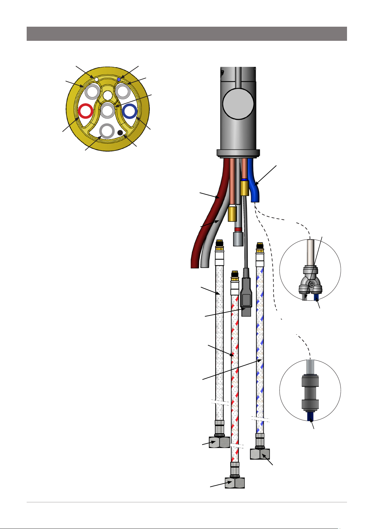
6.1 Configure the tap
• See adjacent diagram.
Section 6 Mains All-in-One tap installation
O-ring
Base block
spider
Base block nut
USB cable
6.2 Cut the hole & mount the tap
• Cut a Ø50mm hole in the worktop / sink.
Ø50mm
Note Make sure the tap location will allow the tap
spout to drain into the sink.
Note All silicone tubes must be cut to size. They must
have a constant fall back to the Command-Centre.
• Fit the o-ring to the underside of the tap.
• Pass tubes and cable through the Ø50mm hole.
• Feed each of the tubes and USB cable evenly between the legs of
the base block spider (see section 6.3).
• Locate the base block spider to the underside of the tap.
• Clamp in position using the base block nut.
• Do not over-tighten.
Installation instructions
803341 V3.00 June 2019 - Zip G4 tap range
Australia Ph: 1800 460 222 , UK Tel: 0345 6 005 005 email: service@zipindustries .co.uk
Technical support
15
Page 16
Section 6 Mains All-in-One tap installation
6.3 Position tubes, hoses & base block spider
Blue marking Red marking
Blue marked
braided hose
Red silicone
tube
Clear silicone tube
(viewed from underneath)
6.4 Connect the tap
• Connect the tap using the
adjacent diagram.
• Match the braided hoses &
extension tubes colour markings.
• Attach the braided hoses
(lubricate seals).
• Do not over tighten.
• For sparkling HydroTaps, connect
the supplied Y connector to the
blue silicone tube, then 1/4” blue
and white pipes as shown.
• For ambient HydroTaps, connect
the supplied connector to the
blue silicone tube, then 1/4” blue
pipe as shown.
• Attach the USB connector to the
Command-Centre.
USB plug, connect
to Command-
Centre
Blue marked
braided hose to
blue marked pipe
on tap
Red marked
braided hose
Blue silicone
tube
USB cable
Red silicone tube -To
BOILING OUTLET on
Command-Centre
Clear silicone
tube - To VENT on
Command-Centre
SPARKLING
OR
models
OR
AMBIENT
models
Blue silicone
tube -To
CHILLED
OUTLET on
Command-
Centre
White pipe
to SPARKLING
OUTLET on
Command-
Centre
Blue pipe
to CHILLED
OUTLET on
Command-
Centre
Installation instructions
16
803341 V3.00 June 2019 - Zip G4 tap range
Red marked
braided hose to
red marked pipe
on tap
Blue marked braided
hose to ambient mains
water supply
Blue pipe to
AMBIENT
Red marked braided
hose to hot mains
water supply
Australia Ph: 1800 460 222 , UK Tel: 0345 6 005 005 email: service@zipindustries .co.uk
OUTLET on
Command-
Centre
Technical support
Page 17
Section 6 Mains All-in-One tap installation
!
6.5 Connect the water supply (detail shown, disassembled and assembled)
Note correct filter orientation. Valves and
fittings must be sealed with PTFE tape.
Australia UK
1/2” BSP (G 1/2)
Isolation valve
15mm - 1/2” BSP(G 1/2)
Ambient mains water supply
Blue marked
Braided hose
to mixer tap
T-piece
(supplied)
Incoming
mains ambient
water supply
via Isolation valve
(not supplied)
Hot mains water supply
Incoming
mains hot
water supply
Male - Male
adaptor
(supplied)
Filter
(supplied)
Male - Female
adaptor
(supplied)
Braided hose
to Command
-Centre inlet
Connect together
via Isolation valve
(not supplied)
Installation instructions
803341 V3.00 June 2019 - Zip G4 tap range
Red marked
Braided hose
to mixer tap
Australia Ph: 1800 460 222 , UK Tel: 0345 6 005 005 email: service@zipindustries .co.uk
Technical support
17
Page 18
All-in-One
vented
7.1 Configure the tap
• See adjacent diagram.
Section 7 Vented All-in-One tap installation
O-ring
Base block
spider
USB cable
7.2 Cut the hole & mount the tap
• Cut a Ø50mm hole in the worktop / sink.
Ø50mm
Note Make sure the tap location will allow the tap
spout to drain into the sink.
Note All silicone tubes must be cut to size. They must
have a constant fall back to the Command-Centre.
Base block nut
• Fit the o-ring to the underside of the tap.
• Pass tubes, hoses and cable through the Ø50mm hole.
• Feed each of the tubes and USB cable evenly between
the legs of the base block spider (see section 7.3).
• Fit the base block spider to the underside of the tap.
• Clamp in position using the base block nut.
• Do not over tighten.
Installation instructions
18
803341 V3.00 June 2019 - Zip G4 tap range
Australia Ph: 1800 460 222 , UK Tel: 0345 6 005 005 email: service@zipindustries .co.uk
Technical support
Page 19
Section 7 Vented All-in-One tap installation
7.3 Position tubes, hoses & base block spider
White marking
White marked
braided hose
Red silicone
tube
Clear silicone tube
(viewed from underneath)
7.4 Connect the tap
• Connect the tap using the
adjacent diagram.
• Match the braided hoses
& extension tubes colour
markings.
• Attach the braided hoses
(lubricate seals).
• Do not over tighten.
• For sparkling HydroTaps,
connect the supplied Y
connector to the blue silicone
tube, then 1/4” blue and white
pipes as shown.
• For ambient HydroTaps,
connect the supplied
connector to the blue silicone
tube, then 1/4” blue pipe as
shown.
• Attach the USB connector to
the Command-Centre.
Blue marking
Blue marked
braided hose
Red
marked
braided
hose
Blue silicone
tube
USB cable
Red silicone tube -To
BOILING OUTLET on
Command-Centre
Clear silicone
tube - To VENT on
Command-Centre
Plain or white
marked braided
hose to white
marked pipe on tap
USB plug, connect
to Command-Centre
Red marked braided
hose to red marked
pipe on tap
Blue marked
braided hose to
blue marked pipe
on tap
Blue silicone tube
-To CHILLED
OUTLET on
Command-Centre
to SPARKLING
OR
SPARKLING
models
OR
AMBIENT
models
White pipe
OUTLET on
Command-
Centre
Blue pipe
to CHILLED
OUTLET on
Command-
Centre
Installation instructions
803341 V3.00 June 2019 - Zip G4 tap range
Plain or white
marked Braided hose
- Flow restrictor
on ambient mains
supply
Red marked braided
hose to MIXER OUT
on Command-Centre
Australia Ph: 1800 460 222 , UK Tel: 0345 6 005 005 email: service@zipindustries .co.uk
Blue marked
braided hose to
MIXER IN on
Command-Centre
Technical support
Blue pipe to
AMBIENT
OUTLET on
Command-
Centre
19
Page 20

Section 7 Vented All-in-One tap installation
!
7.5 Connect the water supply (detail shown, disassembled and assembled)
Note correct filter orientation. Valves and
fittings must be sealed with PTFE tape.
Australia UK
1/2” BSP (G 1/2)
Isolation valve
15mm - 1/2” BSP(G 1/2)
Ambient mains water supply
Plain
Braided hose
to mixer tap
Male - Female
adaptor
(supplied)
Flow restrictor
(supplied)
via Isolation valve
Incoming
mains ambient
water supply
(not supplied)
Filter
(supplied)
Filter
(supplied)
Male - Male
adaptor
(supplied)
T-piece
(supplied)
Male - Male
adaptor
(supplied)
Male - Female
adaptor
(supplied)
Braided hose
to Command
-Centre
mains inlet
Connect together
Installation instructions
20
803341 V3.00 June 2019 - Zip G4 tap range
Australia Ph: 1800 460 222 , UK Tel: 0345 6 005 005 email: service@zipindustries .co.uk
Technical support
Page 21

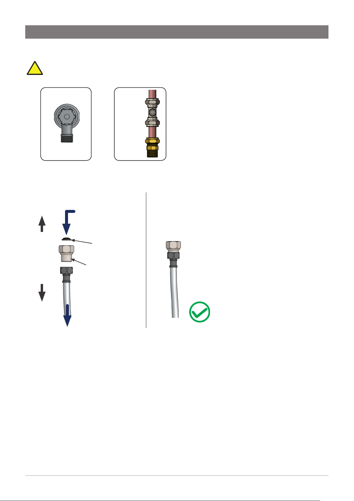
Celsius
8.1 Configure the tap
See adjacent diagram.
Section 8 Mains Celsius tap installation
Upper
rubber
washer
Lower
rubber
washer
8.2 Cut the hole & mount the tap
• Cut a Ø35mm hole in the worktop / sink.
Ø35mm
Brass
washer
Nut
• Slide upper rubber washer in place.
• Mount tap in position on Ø35mm hole.
• Slide lower rubber washer, metal washer & tap nut over the threaded boss, then tighten the tap nut to
secure in place.
• Do not over tighten.
Note Make sure the tap location will allow the tap spout to drain into the sink.
Installation instructions
803341 V3.00 June 2019 - Zip G4 tap range
Australia Ph: 1800 460 222 , UK Tel: 0345 6 005 005 email: service@zipindustries .co.uk
Technical support
21
Page 22
Section 8 Mains Celsius tap installation
8.3 Connect together
• Connect the tap using the
diagrams below.
• Match the braided hoses
& extension tubes colour
markings.
• Attach the braided hoses
(lubricate seals).
• Do not over tighten.
• For sparkling HydroTaps,
connect the supplied Y
connector to the blue silicone
tube, then 1/4” blue and white
pipes as shown.
• Attach the USB connector to
the Command-Centre.
Chilled & Sparkling Chilled or Boiling
Upper rubber
washer
Lower rubber
washer
Brass washer
White pipe
- SPARKLING
OUTLET on
Command-
Centre
Blue pipe
- CHILLED
OUTLET on
Command-
Centre
Vent
Nut
USB
lead
Vent
Upper rubber
washer
Lower rubber
washer
Brass washer
Nut
Red silicone tube
BOILING OUT on
Command-Centre
or
Blue silicone tube
CHILLED OUT on
Command-Centre
Clear silicone tube
VENT on Command-
Centre
(Boiling models only)
USB
lead
Blue marking - Ambient
mains supply
Installation instructions
22
803341 V3.00 June 2019 - Zip G4 tap range
Red marking - Hot mains
supply
Blue marking - Ambient
mains supply
Red marking - Hot mains
supply
Australia Ph: 1800 460 222 , UK Tel: 0345 6 005 005 email: service@zipindustries .co.uk
Technical support
Page 23

Section 8 Mains Celsius tap installation
!
8.4 Connect the water supply (detail shown, disassembled and assembled)
Note correct filter orientation. Valves and
fittings must be sealed with PTFE tape.
Australia UK
1/2” BSP (G 1/2)
Isolation valve
15mm - 1/2” BSP(G 1/2)
Ambient mains water supply
Blue marked
Braided hose
T-piece
(supplied)
to mixer tap
Incoming
mains ambient
water supply
via Isolation valve
(not supplied)
Hot mains water supply
Incoming
mains hot
water supply
Male - Male
adaptor
(supplied)
Filter
(supplied)
Male - Female
adaptor
(supplied)
Braided hose
to Command
-Centre
mains inlet
Connect together
via Isolation valve
(not supplied)
Installation instructions
803341 V3.00 June 2019 - Zip G4 tap range
Red marked
Braided hose
to mixer tap
Australia Ph: 1800 460 222 , UK Tel: 0345 6 005 005 email: service@zipindustries .co.uk
Technical support
23
Page 24
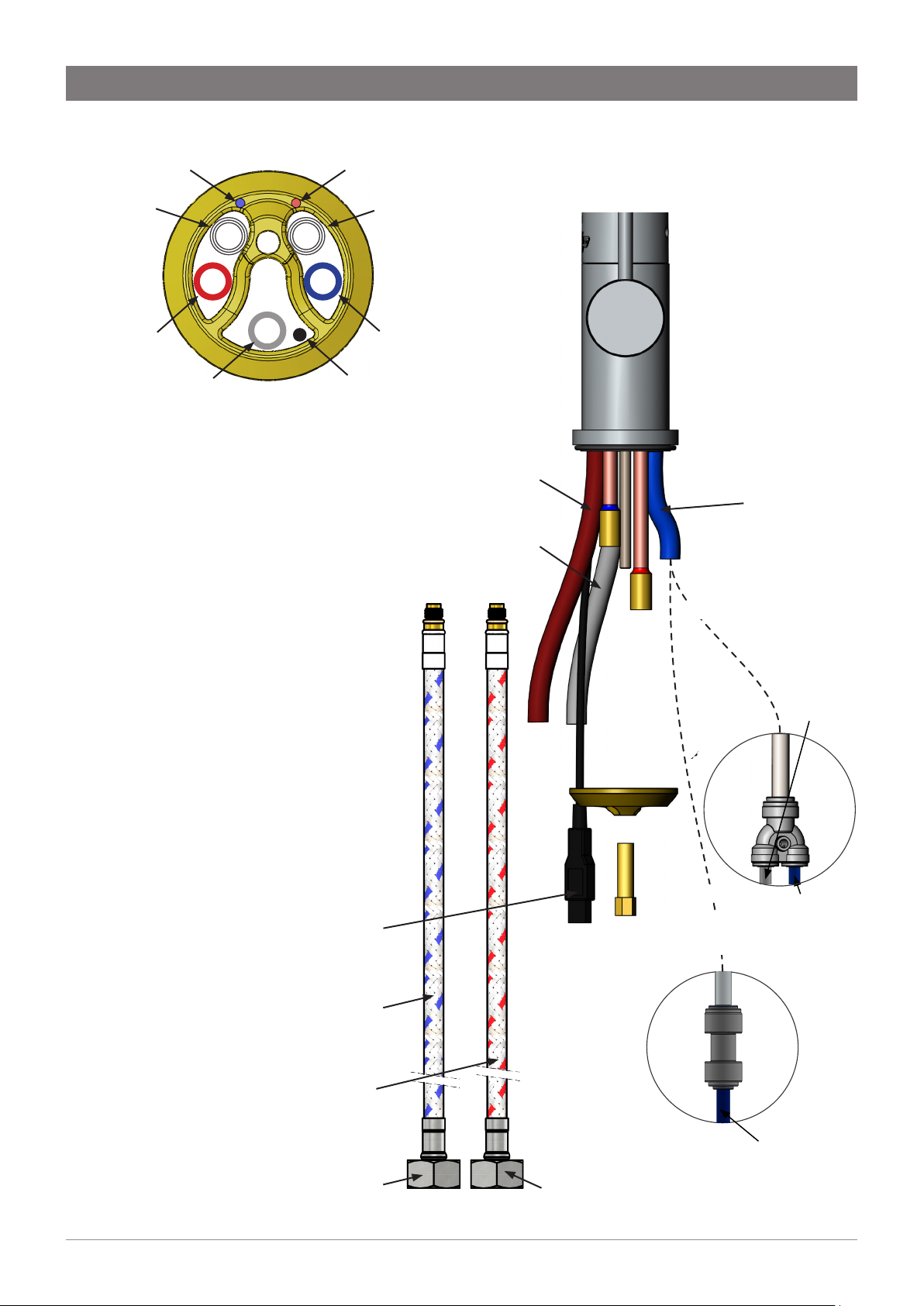
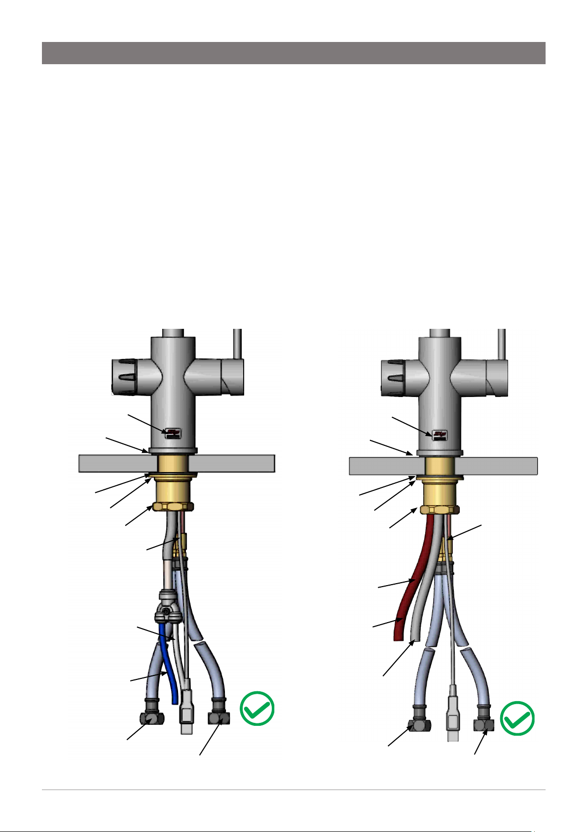
SECTION 9 Mains All-in-One Celsius Arc tap installation
9.1 Configure the tap
• See adjacent diagram.
Threaded boss
Rubber washer
Brass nut
O-ring
Metal washer
3 way silicone
tube
9.2 Outlet configuration
Steam vent
Boiling
water outlet
Mixed
hot & cold water
outlet
Chilled /
sparkling /
filtered water
outlet
USB cable
HOT mains
braided hose
AMBIENT
mains braided hose
Mixed water braided hose
9.3 Cut the hole & mount the tap
• Cut a Ø50mm hole in the worktop / sink.
Ø50mm
Note Make sure the tap location will allow the tap spout
to drain into the sink.
Note All silicone tubes must be cut to size. They must
have a constant fall back to the Command-Centre.
• Fit the o-ring to the underside of the tap then pass tubes, cable and
mixed water braided hose through the Ø50mm hole.
• Fit the large rubber and metal washers over the threaded boss (on the
underside of the worktop).
• Clamp in position using the brass nut.
• Do not over tighten.
Installation instructions
24
803341 V3.00 June 2019 - Zip G4 tap range
Australia Ph: 1800 460 222 , UK Tel: 0345 6 005 005 email: service@zipindustries .co.uk
Technical support
Page 25

9.4 Connect the tap
!
3 ways multi
channel
silicone tube
SECTION 9 Mains All-in-One Celsius Arc tap installation
Boiling
outlet
Steam
vent
Bottom end of
3-Way silicone tube
Chilled
outlet
Connect tap to
Command-Centre
via 3 stainless
steel tubes
Clear silicone
tube - To VENT on
Command-Centre
Red silicone tube -To
BOILING OUTLET on
Command-Centre
Blue silicone tube -To
CHILLED OUTLET on
Command-Centre
Fit braided hoses
to tap connections
in the orientation
shown.
Push fit straight
connector
(supplied), connect
to mixed water
braided hose.
USB plug, connect
to Command-
Centre
Braided hose for
mixed water
For
AMBIENT
OR
models
Blue pipe to AMBIENT
OUTLET on
Command-
Centre
Do not over tighten the braided hoses. Ensure that all tubes and hoses are firmly secured.
Installation instructions
803341 V3.00 June 2019 - Zip G4 tap range
OR
To SPARKLING
OUTLET on
Command-
Centre
For
SPARKLING
models
To CHILLED
OUTLET on
Command-
Centre
Brass nut
Braided hose
with blue
marking -
AMBIENT mains
Braided hose with
red marking - HOT
mains supply.
supply.
Australia Ph: 1800 460 222 , UK Tel: 0345 6 005 005 email: service@zipindustries .co.uk
Technical support
25
Page 26

SECTION 9 Mains All-in-One Celsius Arc tap installation
!
9.5 Connect the water supply (detail shown, disassembled and assembled)
Note correct filter orientation. Valves and
fittings must be sealed with PTFE tape.
Australia UK
1/2” BSP (G 1/2)
Isolation valve
15mm - 1/2” BSP(G 1/2)
Ambient mains water supply
Blue marked
Braided hose
to mixer tap
Incoming
mains ambient
T-piece
(supplied)
water supply
via Isolation valve
(not supplied)
Hot mains water supply
Incoming
mains hot
water supply
Male - Male
adaptor
(supplied)
Filter
(supplied)
Male - Female
adaptor
(supplied)
Braided hose
to Command
-Centre
mains inlet
Connect together
via Isolation valve
(not supplied)
Installation instructions
26
803341 V3.00 June 2019 - Zip G4 tap range
Australia Ph: 1800 460 222 , UK Tel: 0345 6 005 005 email: service@zipindustries .co.uk
Technical support
Page 27

End of life disposal
The use of this crossed out wheeled bin logo indicates that electrical and electronic products
needs to be disposed of separately to any other household waste.
Within each of the European Union member countries, provisions have been made for collection
and recycling of unwanted electrical and electronic equipment. In order to help preserve our
environment we ask that you dispose of this product correctly.
Installation instructions
803341 V3.00 June 2019 - Zip G4 tap range
Australia Ph: 1800 460 222 , UK Tel: 0345 6 005 005 email: service@zipindustries .co.uk
Technical support
27
Page 28

AU02691
WMKA21012
AS 3498
Zip Heaters (Aust) Pty. Ltd
67 - 77 Allingham Street, Condell
www.zipwater.com
Installation instructions
28
803341 V3.00 June 2019 - Zip G4 tap range
ABN 46 000 578 727
Park,
NSW 2200
Postal: Locked bag 80,
Bankstown 1885
Australia
Tel (02) 9796 3100
Free Call 1 800 638 633
Zip Water UK
14 Bertie Ward Way, Dereham,
Norfolk NR19 1TE
0345 6 005 005
sales@zipindustries.co.uk
www.zipwater.co.uk
Technical support
Australia Ph: 1800 460 222 , UK Tel: 0345 6 005 005 email: service@zipindustries .co.uk
 Loading...