

Zip HydroTap ABB10FXC, HydroTap ABC30/30FXC, HydroTap ABB30FXC, HydroTap B1OC, HydroTap B3OC Installation Instructions And Operating Manual
...Page 1
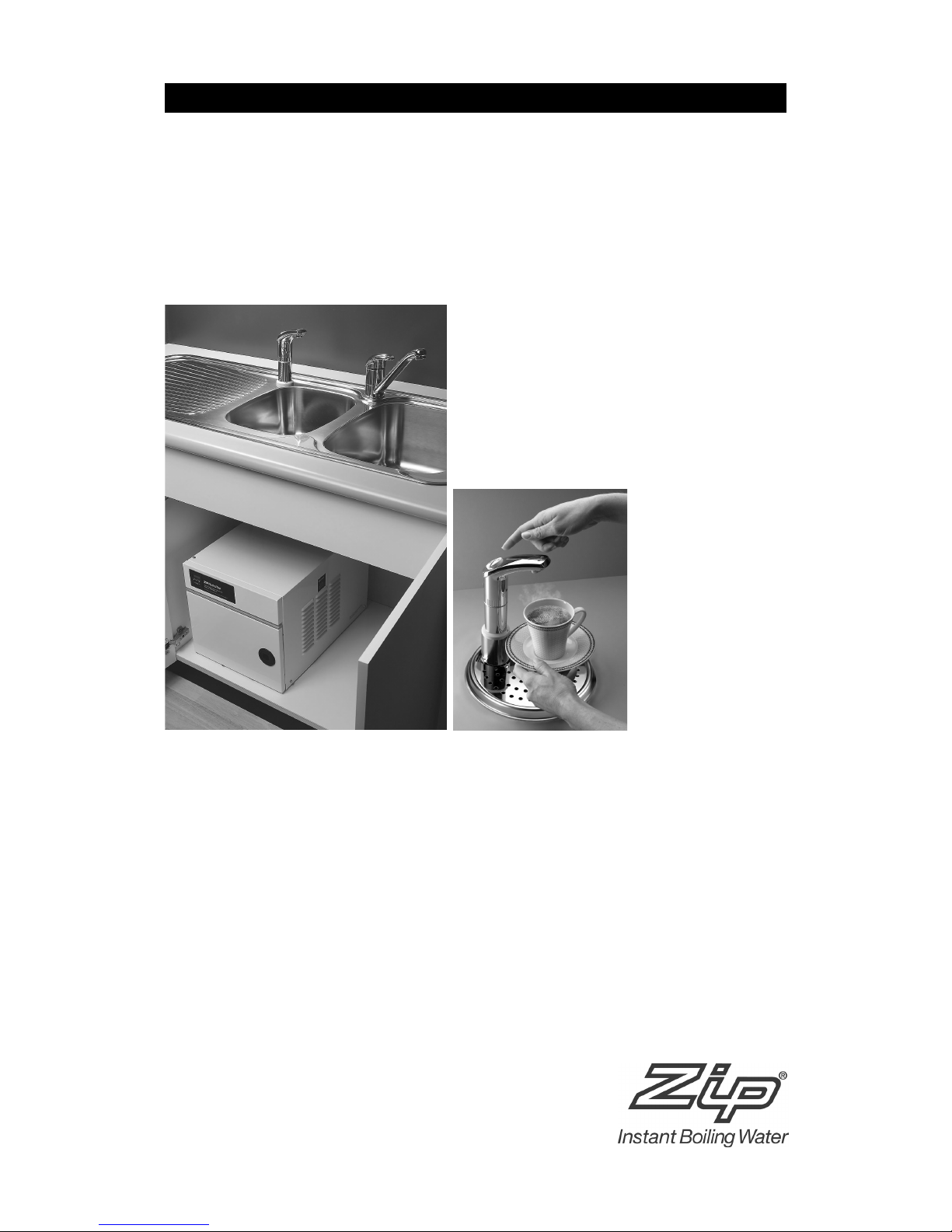
Zip HydroTap
Filtered boiling and chilled water for kitchens and tea rooms
73078 Zip HydroTap ABC10/30FXC
73119 Zip HydroTap ABC30/30FXC
73081 Zip HydroTap ABA10FXC
73123 Zip HydroTap ABA30FXC
73118 Zip HydroTap ABB10FXC
73121 Zip HydroTap ABB30FXC
73110 Zip HydroTap B1OC
73111 Zip HydroTap B3OC
Installation Instructions and Operating Procedures
®
Page 2

Page 2 of 20 Zip HydroTap Installation and Operating Instructions - 82872 - July 2003
Page 3

Zip HydroTap Installation and Operating Instructions - 82872 - July 2003 Page 3 of 20
Contents
Read These Warnings First . . . . . . . . . . . . . . . . . . . . . . . . . .4
Models covered by these instructions . . . . . . . . . . . . . . . . . .5
Installation Requirements . . . . . . . . . . . . . . . . . . . . . . . . . . .5
Special tools required . . . . . . . . . . . . . . . . . . . . . . . . . . . . . .6
Installation procedure . . . . . . . . . . . . . . . . . . . . . . . . . . . . . .6
Step A - Installing the tap (all models) . . . . . . . . . . . .6
Step B - Installing the undersink unit (all models) . . .7
Step C - Connecting the tap . . . . . . . . . . . . . . . . . . .7
Installation with Tap Font . . . . . . . . . . . . . . . . . . . . . . . . . . . .8
Tap Font Mounting Template . . . . . . . . . . . . . . . . . . . . . . . . .a-d
Installation procedure Continued . . . . . . . . . . . . . . . . . . . . . .13
Step C - Connecting The Tap continued . . . . . . . . . .13
Step D - Connecting the water supply (all models) . .14
Step E - Testing and commissioning . . . . . . . . . . . . .14
Solving general problems . . . . . . . . . . . . . . . . . . . . . . . . . . .15
Operating the Tap . . . . . . . . . . . . . . . . . . . . . . . . . . . . . . . . .16
Cleaning . . . . . . . . . . . . . . . . . . . . . . . . . . . . . . . . . . . . . . . .17
Replacing the Filter . . . . . . . . . . . . . . . . . . . . . . . . . . . . . . . .17
Setting the Energy Saver Timer . . . . . . . . . . . . . . . . . . . . . . .18
Setting Correct Time . . . . . . . . . . . . . . . . . . . . . . . . .18
Programming Power ON & OFF . . . . . . . . . . . . . . . . .18
Warranty . . . . . . . . . . . . . . . . . . . . . . . . . . . . . . . . . . . . . . . .19
Contact Details . . . . . . . . . . . . . . . . . . . . . . . . . . . . . . . . . . .20
Page 4

Page 4 of 20 Zip HydroTap Installation and Operating Instructions - 82872 - July 2003
Read These Warnings First
Safety
Do not allow young children, handicapped or infirm persons, to use the Zip
HydroTap without supervision
Refrigerant
The Zip HydroTap Chilling unit contains 134A refrigerant under pressure. No
part of the unit should be exposed to a naked flame. Maintenance of
refrigeration unit must be carried out by an accredited service provider or
qualified refrigeration mechanic.
Qualifications
If any power cord or plug is damaged it must be repaired only by a
qualified technician.
To avoid hazards, all installation procedures must be carried out by a
suitably qualified tradesperson.
Venting
Sometimes steam and/or boiling water may discharge through the vent at
the rear of the tap shank. If the tap is not installed on a sink, the pipe to
this outlet must be disconnected and plumbed away to a safe location
according to local plumbing bylaws and regulations.
Lifting
Take care when lifting the Zip HydroTap undersink unit. Some units may
exceed safe lifting limits. Do not lift without assistance. The weights of the
units are given in the table under Installation Requirements (page 5).
Airflow
Proper air circulation must be provided. The system will operate
satisfactorily only if the recommended air gaps are provided. If this is not
possible, ventilation slots must be cut into the top AND bottom of the
cupboard door. Make sure that the ventilation grilles of the undersink unit
are not obstructed.
Altitude
At altitudes over 500 metres above sea level, the thermostat temperature
may require adjustment. Contact your Zip Service Provider.
Filter
For models ABC, ABA and ABB only:
The Zip HydroTap filter timer is preset to nine months to provide troublefree flow and operation in most installations. Local water quality conditions
may require an alteration to this time. In areas where the water has a high
concentration of sediment, the preset time may be shortened to avoid poor
flow, taste or odour situations. In areas where the water quality is above
average, lengthening the preset time may be desirable, but not essential.
If any of these changes are needed, contact your Zip Service Provider.
Page 5
Zip HydroTap Installation and Operating Instructions - 82872 - July 2003 Page 5 of 20
# Section Heading
These Installation Instructions cover the entire Zip HydroTap range. Use the
chart on the left to identify the model you are using:
Model:
ABC = Filtered, boiling and chilled, timer
ABA = Filtered, boiling and ambient
ABB = Filtered, boiling only
B = Boiling only (unfiltered)
Boiling Water Capacity:
10 = 10 cups 30 = 30 cups
Chilled Water Capacity: (ABC only)
30 = 30 cups
Filtration: (ABA, ABB and ABC only)
FX = Sub micron filter
Models covered by these instructions
Before installing ensure that the following have been provided at the
installation site:
• Sufficient space in the cupboard to install the undersink unit in
accordance with these Installation Instructions. A table of dimensions is
given below.
• A water supply connection with isolating valve inside the cupboard
within reach of the 750 mm flexible connection and positioned so that
the connection point and the stop cock will not be obstructed when the
undersink unit is installed.
• A water supply which can deliver 2 litres per minute flow rate at
minimum of 1.5 Bar (150 kPa) flow (dynamic) pressure.
• Power supply connection to the heater via a double pole fused spur with a
minimum break rating of 13 amps.
• Cold water supply with a minimum working pressure of 1.5 bar (150 kPa)
and a maximum working pressure of 10 bar (1000 kPa) connected via an
isolation valve.
Important:
Do not proceed with the installation if these requirements are not met.
Capacity 10/30 Height Depth Width Weight kg/(lb)
mm (in.) mm (in.) mm (in.) Empty Full
ABC 340 (13.4) 510 (20) 340 (13.4) 30 (66.1) 36 (79.3)
ABA and ABB 343 (13.5) 343 (13.5) 287 (11.3) 14 (30.8) 16 (35.2)
B 340 (13.9) 277 (10.9) 194 (7.6) 12 (26.4) 14 (30.8)
Capacity 30/30 Height Depth Width Weight kg/(lb)
mm (in.) mm (in.) mm (in.) Empty Full
ABC 383 (15) 510 (20) 477 (18.8) 32 (70.5) 42 (90.3)
ABA and ABB 383 (15) 433 (17) 340 (13.4) 18 (39.7) 23 (50.7)
B 380 (15) 369 (14.5) 284 (11.2) 16 (35.2) 21 (46.2)
Installation Requirements
ABC
Model
10/
Boiling
Water
Capacity
30
Chilled
Water
Capacity
FX
Filtration
Page 6
Page 6 of 20 Zip HydroTap Installation and Operating Instructions - 82872 - July 2003
In addition to normal tools, the following will be required:
• 13.5 mm diameter sheet metal hole punch
• 35 mm diameter sheet metal hole punch.
Special tools required
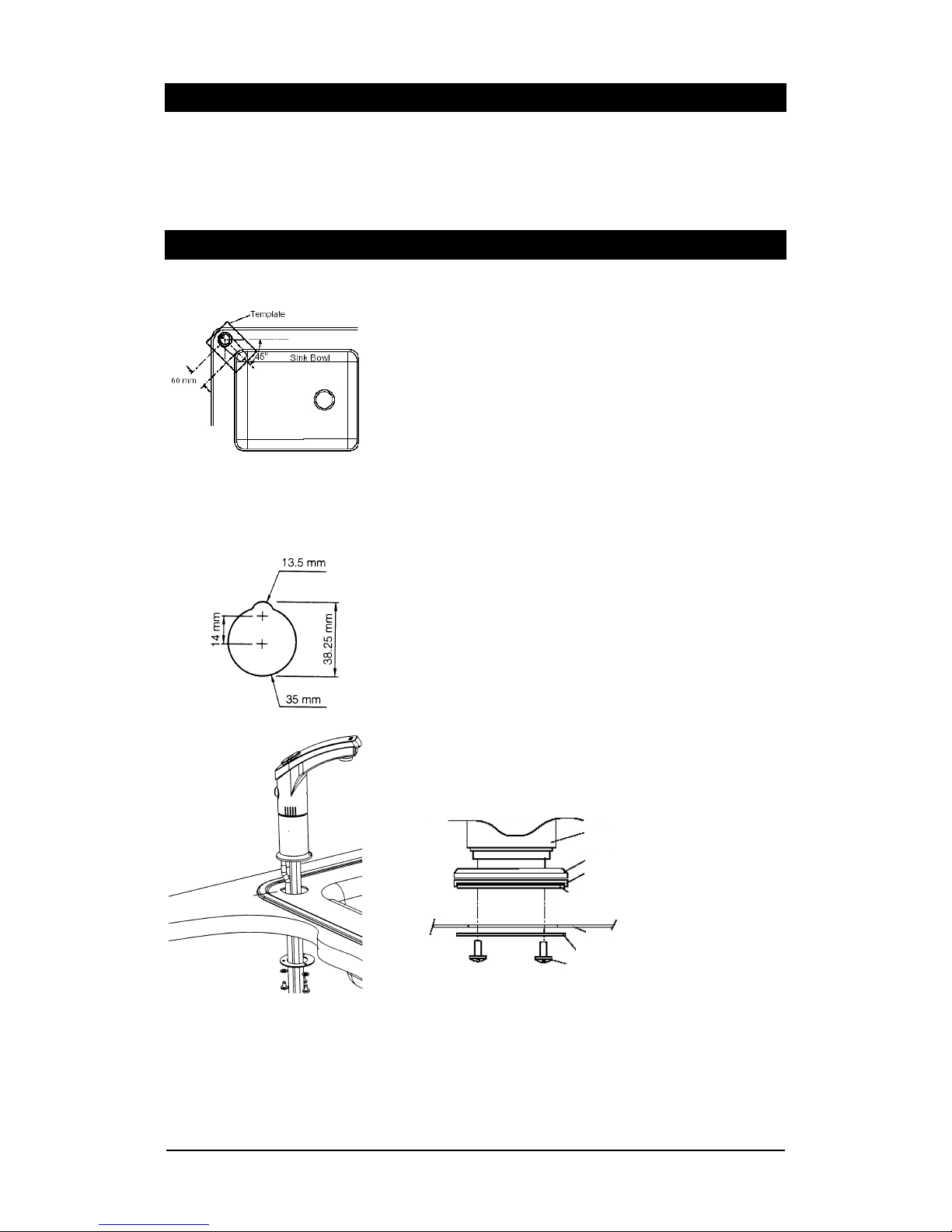
Step A - Installing the tap (all models)
Locate the stick-on tap hole mounting template in the accessory envelope
and apply to a flat surface at the left rear corner of the sink. Follow the
instructions on the template.
Make sure that the tap will be able to drain into the sink.
Mark the two hole centres and cut the small hole using a 13.5 mm sheet
metal hole punch
Cut the large hole using a 35-mm sheet metal hole punch.
Install the tap, making sure it is adequately sealed.
To ensure proper sealing, make sure that the tap mounting items are
assembled in the order shown in the Assembly Detail diagram below.
Ensure that the upper plate is properly inserted in the recess on the
bottom of the sealing ring.
Tighten the fixing screws firmly.
Installation procedure
Tap Body
Base Ring
Sealing Ring
Upper Metal Plate (Fits into recess
in sealing ring)
Sink
Lower Metal Plate
Fixing Screws
Assembly Detail
Page 7

Zip HydroTap Installation and Operating Instructions - 82872 - July 2003 Page 7 of 20
Step B - Installing the undersink unit (all models)
Before positioning heater connect the braided water inlet hose (supplied) to
cold water inlet on unit. This is located on the left hand side.
Position the Zip HydroTap undersink unit as closely as possible to directly
beneath the Zip HydroTap tap head.
The connection tubes supplied with the tap head assembly CANNOT be
lengthened.
Leave at least a 50 mm air-gap without obstruction on each side of the
unit.
Fasten the fixing brackets (located behind the access door) to the cupboard
floor using screws provided.
Adjust both cupboard door hinges and attach the supplied rubber door
buffers to the doors to create a 4 mm air-gap between the doors and the
cupboard. This is the minimum ventilation requirement.
Caution: Proper air circulation must be provided. The system will operate
correctly only if the recommended air gaps are achieved during installation.
If this is not possible, ventilation slots must be cut into the top AND bottom
of the cupboard door. Make sure that ventilation grilles are not obstructed.
Allow access to water inlet located on the left hand side of undersink unit.
Step C - Connecting the tap
Model ABC
Mount the External Chilled Water Expansion Chamber (ECWEC) into the cold
water outlet on the top of the undersink unit by pressing down firmly into
the John Guest fitting.
Measure and trim the blue tube and connect it to the top centre outlet of
the ECWEC.
Measure and trim the small tube and connect it to the offset outlet on the
top of the ECWEC.
Measure and trim the red marked tube and connect it to the hot water
outlet on the top of the undersink unit.
Measure and trim the unmarked tube and connect it to the vent outlet on
the top of the undersink unit
Connect the tap electrical connector to the cord attached to the undersink
unit. Align the pins carefully and do not force the plug. Clamp the cable to
the wall with clip provided so that the plug hangs vertically.
Note: When trimming any silicon tubes trim to minimum length, do not
loop the excess or allow kink of the tubes. When connecting, slide
the tube over the pipe at least 25 mm.
Installation procedure continued
Boiling
Water (red)
Vent
Chilled
Water
(blue)
Vent
ECWEC
Electrical
4 mm
+50 mm
+50 mm
Page 8

Page 8 of 20 Zip HydroTap Installation and Operating Instructions - 82872 - July 2003
Installation with Tap Font
Features
The sump built into the Tap-Font drains away to any nearby waste.
Also elevates tap outlet to provide 210 mm clearance for pots.
Positioning
Position Tap-Font as close as possible to directly above under-sink unit.
Never extend either the cable or tubing attached to the head assembly.
If possible position tray on bench so the tap is to the rear, then rotate base
45 degrees anti-clockwise.
Drilling
Use paper template to drill 57 mm hole, 45 mm hole and 4 screw holes.
For timber bench, drill 3 mm screw holes for timber screws provided.
For granite or similar, drill 6 mm holes for stainless screws provided.
Assembling
Fix clamp plate to bench top using 4 "timber" or "stainless" screws
provided.
Remove silicon vent tube from base of tap assembly as shown in diagram.
Pass electrical cable, then tubes, from tap base through pedestal as shown.
Check cable and tubes to ensure all are free, none are twisted or kinked.
Fix the tap head assembly to pedestal using 3 pedestal screws.
Apply sealant to thread on brass tube supplied, screw into pedestal base.
Attach disconnected silicon vent tube to brass vent tube as shown in photo.
Apply a light bead of sealant to the underside edge of the sump tray.
Position the tray so the sump drain outlet lines up with the fixing plate hole.
Swivel tray so pedestal is positioned above largest hole in bench.
Pass all cables and tubes from pedestal through largest hole in bench.
Fit clamp spacer and lock nut on to drain bush and tighten securely.
Clean off any sealant squeezed out around sump tray during clamping.
Connecting
Install the waste clamp in an accessible position on the "sink side" of drain
trap and as high as possible above the trap water line.
The waste clamp must never be installed on the "drain side" of drain trap.
To drill access hole into trap, remove nut and olive from clamp fitting and
select drill bit to fit inside diameter of the clamp fitting hole.
Fasten clamp to drain pipe and drill access hole through hole in clamp.
Apply sealant to thread on brass tube supplied and fasten tube to clamp
with nut and olive, referred to above.
Apply sealant to similar brass tube and fit to drain bush on sump.
Connect tube on clamp to tube on sump using flexible tubing provided.
Ensure flexible tube has a continuous fall from sump to clamp.
Remove protective coating from stainless steel, wipe clean and fit
removable drip plate. Fit remaining tubes and cable as shown on page 7.
Inserting screw through pedestal
to underside of tap.
An alternative to mounting the Zip
HydroTap tap head on a sink.
Use Zip HydroTap Tap-Font kit to install
tap anywhere on bench.
To order Tap-Font kit, quote Zip part
number 99057.
Tap Assembly
Remove
Flexible
vent Tube
Vent Pipe
Drip Plate
Brass Outlet
Tube
Clamp
Spacer
Tap
Assembly
Waste
Clamp
Brass Drain
Tube
Clamp Plate
Bench Top
Flexible
Drain Tube
Lock Nut
Drain Tube
Sump
Sump Tray
Pedestal Screws
Pedastal
Page 9

Zip HydroTap Installation and Operating Instructions - 82872 - July 2003 Page a
Detach this papertemplate and use it to
position your Zip Hydrotap Tap-Font on
your kitchen bench.
Page 10

80 mm
45 mm
MINIMUM
CLEARANCE
FROM REAR
WALL.
CIRCUMFERENCE
OF TAP-FONT BASE
SMALL HOLE
SCREW HOLE
SCREW HOLE
Page 11

57 mm
SCREW HOLE
SCREW HOLE
LARGE HOLE
Page 12

Page d Zip HydroTap Installation and Operating Instructions - 82872 - July 2003
Detach this paper template and
use it to position your Zip Hydrotap
Tap-Font on your kitchen bench.
Page 13

Zip HydroTap Installation and Operating Instructions - 82872 - July 2003 Page 13 of 20
Connecting the Tap continued
Models ABA and ABB
Measure and trim the red marked tube and connect it to the hot water
outlet on the top of the undersink unit.
Measure and trim the unmarked tube and connect it to the vent outlet on
the top of the undersink unit.
For ABA only, measure and trim the blue marked tube and connect to the
ambient water outlet on the top of the undersink unit..
Connect the tap electrical connector to the cord attached to the undersink
unit. Align the pins carefully and do not force the plug. Clamp the cable to
the wall with clips provided so that the plug hangs vertically.
Model B
Measure and trim the red marked tube and connect it to the hot water
outlet on the top of the undersink unit.
Measure and trim the unmarked tube and connect it to the vent outlet on
the top of the undersink unit.
Connect the tap electrical connector to the cord attached to the undersink
unit. Align the pins carefully and do not force the plug. Clamp the cable to
the wall with clips provided so that the plug hangs vertically.
Note: In some circumstances, steam and/or boiling water may discharge
from the vent at the rear of the tap shank. If the tap is not installed
on a sink, the pipe to this vent must be removed from the spigot at
the base of the tap and plumbed away to a safe location in
accordance with local plumbing regulations
Installation procedure continued
Electrical
Vent
Water
(ambient)
Boiling Water
Electrical
Boiling
Water
Vent
Vent
Page 14

Page 14 of 20 Zip HydroTap Installation and Operating Instructions - 82872 - July 2003
Step D - Connecting the water supply (all models)
To prevent sediment from entering the Zip HydroTap at connection, flush
water through the supply thoroughly before connection to the HydroTap.
Open the access door and check that the filter is in place and secure.
Connect water supply to undersink unit using flexible hose already
attached.
Step E - Testing and commissioning
Check that all installation steps have been carried out correctly
Locate the red fill switch on the upper left-hand side of the undersink unit
and check that it is in the Fill (Up) position.
Connect the undersink unit to the power and turn the power and water on.
Check that the tap-head lamps operate according to the model as follows:
Models ABC and ABB: All three lamps on
Model ABA: Lamps 1 and 3 on, lamp 2 off
Model B: Lamps 1 and 2 on, lamp 3 off
The boiling water tank is now filling and after a short time, water will start
to flow from the tap. Allow the water to flow for five minutes to charge the
filter and ensure clean clear water. Allow sufficient water to flow through
the filter to clear the water of carbon fines.
Set the Fill switch to the On (down) position. The water will stop flowing.
For Model ABC, press and hold the blue button for about 1 minute after
water begins to flow.
Check that the lamps operate according to the model as follows:
Model ABC: Lamps 1 and 2 flash once per second and lamp 3 flashes once
per minute
Model ABA: Lamp 1 flashes once per second, and lamp 3 flashes once per
minute.
Model ABB: Lamp 1 flashes once per second, lamp 2 stays on, and lamp 3
flashes once per minute.
Model B: Lamp 1 flashes once per second and lamp 2 stays on.
Check all connections for water leaks, rectify as necessary.
Write the date on the filter cartridge (all models except model B).
After approximately 15 minutes, lamps which were flashing (lamps 1 and/or
2) will stop flashing and stay on to indicate that the water has reached the
correct temperature. Lamp 3 will continue to flash once per minute.
Test Water delivery from the tap checking for appropriate temperatures.
Use cable clips to tidy and secure wiring.
If required for Model ABC, set up the energy saver timer as detailed on page 13.
Installation procedure continued
Water connection
Stop
cock
Flexible
hose
Fill switch location
Tap head lamps
Lamp 3
Lamp 2
Lamp 1
Chilled (Model ABC) or ambient
(Model ABA) water button
Boiling water
button
On models ABB and B
both buttons dispense
boiling water
Electrical Connection
Cold Supply
Hot outlet
Vent
Page 15

Zip HydroTap Installation and Operating Instructions - 82872 - July 2003 Page 15 of 20
Symptom Possible Cause Solution
The filter lamp is flashing once per The filter is outside its usable time Change the filter
sec (not model B)
The water flow is slow The filter is blocked. (not model B) Change the filter
There is a problem with the water Ask you Zip service provider to
supply pressure test the water pressure
Isolating valve not fully open
The unit is not dispensing water and The power is off Check the power supply
all the lamps are off The timer is in power save mode (off)
(model ABC only) Check the timer settings
The tap is not connected properly to the
undersink unit Call your Zip service provider
The safety shutdown is activated (tray Turn off the power and the
flooded) and the red lamp is faulty water and call your Zip service
(not model B) provider
The boiling water is not hot and the The unit is being used in excess of its Change your usage pattern or
red lamp is flashing rated capacity upgrade to a larger unit
Boiling water or steam is coming The unit is being used in short bursts Dispense boiling water for two
from tap vent too often minutes to drain.
Dispense no less than one up at
a time
The red lamp is flashing three times There is a problem with the Turn off the power and the water
a second undersink unit and call your your Zip Service
provider
The red lamp flashes once a second There is a problem with the Turn off the power and the water
when the water is hot undersink unit and call your Zip service
provider
The boiling water is running The Fill switch is in the wrong Move the Fill switch on the left o
continuously position (Up) side of the unit to the down
position
The boiling water is not dispensing The Tap safety lock is set Check the setting of the Tap lock
and the red lamp is on There is no water supply Check the water supply
The filter is blocked. (not model B) Change the filter
There is a problem with the Turn off the power and the water
undersink unit and call your Zip service
provider
Solving general problems
Symptom
The chilled water is not cold and
the blue lamp is flashing
Chilled water is coming from the
tap vent
The blue light is flashing three
times a second
The chilled water is not dispensing
and the blue lamp is on
Possible Cause
The unit is being used in excess of
its rated capacity
The unit is being used in short
bursts too often
There is a serious problem with the
undersink unit
There is no water supply
The filter is blocked
There is a problem with the
undersink unit
Solution
Change your usage pattern or
upgrade to a larger unit
Dispense chilled water for two
minutes to drain.
Dispense no less than one cup at at
time
Turn off the power and the water
and call your Zip service provider
Check the water supply
Change the filter
Turn off the power and the water
and call your Zip service Provider
Solving problems with the chilled water (Model ABC only)
Page 16

Page 16 of 20 Zip HydroTap Installation and Operating Instructions - 82872 - July 2003
Operating the Tap
Blue Chilled Water Light
On all the time:
This indicates that the chilled water is within the usable temperature
range.
Flashing slowly (once every second):
This indicates that the chilled water is not at temperature. Wait up to 30
minutes. When the chilled water is ready, the light will stop flashing. Note:
The Zip HydroTap is designed to dispense chilled water in the temperature
range 5°C to 10°C. During heavy usage, the temperature can rise out of
this range.
Flashing rapidly (three times a second):
This indicates that there is a fault in the undersink chilling system. Call a
Zip service provider.
Red Boiling Water Light
On all the time:
This indicates that the boiling water is ready.
Flashing slowly (once every second):
This indicates that the boiling water is not at required temperature. Wait
up to 15 minutes. When the boiling water is ready, the light will stop
flashing.
Flashing rapidly (three times a second):
This indicates that there is a leak in the undersink water system and the
unit will be shut down. In this case call Zip services.
Filter Change Light Flashing slowly (once every minute):
The light will flash once every minute when the filter is within its specified
lifespan.
Flashing rapidly (once per second):
The light will flash once per second when the filter is due for replacement.
Refer to section 3, "Replacing the filter".
Boiling Water Button
Press and hold down to pour boiling water.
Chilled Water Button
Press and hold down to pour chilled water.
Child Proof Lock
The child proof lock can be activated to prevent boiling water flowing if the
hot button is inadvertently pushed.
To turn on, rotate the red button to the locked position.
To turn off, rotate the red button to the unlocked position.
To operate the tap when the child proof lock is activated, press and hold
the child proof lock button in and then press the hot water button.
Note: Whilst the Zip HydroTap is designed to dispense water within 2°C to
6°C of boiling point. The temperature can drop out of this range during
heavy usage.
Dispensing Boiling Water with
Child lock deactivated.
Dspensing Boiling Water with
Child proof lock active
Red
(Boiling)
Blue
(Chilled)
Filter
status
Dispensing Chilled Water
Page 17

Zip HydroTap Installation and Operating Instructions - 82872 - July 2003 Page 17 of 20
Cleaning
Do not use strong, corrosive, spray or abrasive cleaners. Clean with a soft
cloth or brush and mild soap and water.
Do not spray water over the tap as it may damage the low-voltage
electronics.
Undersink units must never be cleaned with water jets.
The Zip HydroTap timer is set to remind you to replace your filter every 9
months. When a filter change is due, the Change Filter light will come on and
remain on until reset.
Depending on local water quality conditions and usage, the filter may require
changing every 6 to 12 months. You may also need to replace the filter if you
notice unpleasant odours or tastes, or if the flow rate of the tap is slow.
Some water may drip from the filter head (socket) during replacement. Keep a
bucket and towel handy to catch drips and mop up any spills.
1. Locate service valve in the water supply line and turn off the water
supply.
2. Grasp filter cartridge and twist right to left one quarter turn until it stops.
3. Ease cartridge downwards to detach it from the filter head (socket).
4. Do not tilt the cartridge as dirty water may spill from it if tilted.
5. Unpack replacement cartridge and write today’s date where shown on the
label.
6. Avoid bacterially contaminating cartridge top whilst inserting into head.
7. Align cartridge tabs with the slots on the under-side of the filter head.
8. Slide cartridge upward into head and rotate left to right until it stops.
9. Open the service valve and check filter head for leaks. Refit if leaking.
10. To purge air from filter follow purging procedure described below.
11. Wipe up any spills and dispose of spent filter cartridge and packaging
thoughtfully.
12. Run the hot or cold water through the tap continuously for 5 minutes.
13. Reset filter status, by pushing the red button positioned to the left of the
cartridge.
Note: Freshly installed filters may cause water to appear milky. The water
should clear after running a few litres of water through the filter.
Replacing the Filter
• Warning: If the Zip HydroTap is switched off for a long period of time (one
weekend plus), run water through the chilled water outlet for at least 5
minutes before consumption.
Number of users per Zip HydroTap 10 50 100
Estimated weekly consumption (litres) 50 250 500
Filter change - sub-micron (weeks) 52 22 11
Page 18

Page 18 of 20 Zip HydroTap Installation and Operating Instructions - 82872 - July 2003
If you do NOT wish to programme the timer to turn the Zip HydroTap on and
off daily, you may ignore the following instructions.
The Zip HydroTap will operate continuously if you do not programme the
timer at all.
If you do wish to programme the timer to turn the Zip HydroTap on and off
daily, first set the timer to the correct time, then follow the instructions set
out below. You can programme the timer to turn the Zip HydroTap on and
off up to 3 times daily.
Setting Correct Time
Hold down the button until the following 3 steps are completed.
1. Change day:
With button held down, press button “d”.
A triangle points to day currently selected.
Days are marked 1 to 7.
Day 1 = Monday, Day 7 = Sunday.
Press and release button “d” until correct day is selected.
2. Change hour:
With button held down, press button “h”.
Screen shows hour currently selected.
Clock works on 24 hour time: 1 = 1 am, 13 = 1 pm.
Press and release button “h” until correct hour is selected.
3. Change minute:
With button held down, press button “m”.
Screen shows minute currently selected.
Press and release button “m” until correct minute is selected.
When, day, hour and minute are correct, release button.
Programming Power ON & OFF
1. Press and release the “Prog” button once.
2. Display will show first setting: (—:— 1 ON).
3. Triangle over “1” indicates setting for Monday.
4. Press and release “h” and “m” buttons to set ON time.
5. Press and release the “Prog” button once.
6. Display will show second setting: (—:— OFF).
7. Triangle over “1” indicates setting for Monday.
8. Press and release “h” and “m” buttons to set OFF time.
9. Press and release “Prog” button once.
Repeat procedure to set further Monday ON and OFF times.
Or press and release “d” to go directly to first setting next day.
Programme ON and OFF for each day of week.
When complete, press and release button.
During programming a 40 second delay will return you to clock display.
To return to programming point, press “Prog” and “d” buttons together.
To review programme, press and release “Prog” repeatedly.
To erase any ON or OFF setting displayed, press “h” and “m” together.
For total reset, press “d”, , “m” and buttons together.
To over-ride OFF setting, press and release button – will remain ON
until the next programmed OFF time.
To lock timer ON or OFF press “m” and buttons together. Check
screen: black dot over ON or OFF indicates timer locked.
Setting the Energy Saver Timer
prog.
m
h
d
Page 19

Zip HydroTap Installation and Operating Instructions - 82872 - July 2003 Page 19 of 20
Warranty
The Zip appliance you have chosen is precision-built from the finest
materials available and should give many years of trouble free service.
Certain warranties may be implied by law into your contract with Zip. The
warranty provided below is additional to these implied warranties and
nothing set out below shall limit your statutory rights or rights at law.
Zip Heaters (UK) Pty Ltd warrants that, should any part fail within 12
calendar months of installation, that part will be repaired or replaced free of
charge by Zip or its Distributor or Service Provider, except as set out below,
provided the appliance is installed and used strictly in accordance with the
instructions supplied, and that failure is not due to accident, misuse, abuse,
unsuitable water conditions, or to any alteration, modification or repair by
any party not expressly nominated by Zip.
No costs are payable by the customer other than any mileage or travellingtime charges incurred by a Zip Service Provider or the cost of removal,
cartage and re-installation of any component of the appliance if it needs to
be returned for repair to Zip or its Distributor.
This warranty does not cover damage resulting from non-operation of the
appliance or consequential damage to any other goods, furnishings or
property.
No warranty applies to the life of any filtration cartridge installed with the
appliance as cartridge life may vary according to water quality and the rate
of water consumption.
Zip does not exclude, restrict or modify any liability that cannot be
excluded, restricted or modified or which cannot, except to a limited extent,
be excluded, restricted or modified as between the owner or user and Zip
under the laws applicable.
Furthermore, this warranty does not displace any statutory warranty, but, to
the extent to which Zip is entitled to do so, the liability of Zip under any
statutory warranty will be limited at Zip's option to the replacement of the
appliance or supply of equivalent appliance, the payment of the cost of
replacing the appliance or acquiring an equivalent appliance, or the
payment of the cost of having the appliance repaired or the repair of the
appliance.
Registering Your Purchase
Registering your Zip installation on the Zip website may help to establish
date of installation should it become necessary to service the appliance
under terms of the Zip warranty. To register your installation go to
www.zipheaters.co.uk and look under the heading "Warranty".
Page 20

Page 20 of 20 Zip HydroTap Installation and Operating Instructions - 82872 - July 2003
The standard cup referred to in this publication is 167 ml (6 fl oz).
The standard glass is 200 ml (7 fl oz).
The terms "Zip", "HydroTap" and "Hydroboil" are registered trade marks.
Zip products described in this publication are manufactured under one or more of the following
patents: AU675601, AU637412, AU635979, GB0422305, GB2065848, US4354049, US5103859,
and US5099825. Other patents are in force and patent applications are pending.
Zip Heaters (UK) Ltd
14/15 Bertie Ward Way
Rash’s Green Dereham
Norfolk NR19 1TE
www.zipheaters.co.uk
Telephone: 0870 608 8888
Facsimile: 01362 692448
Contact Details
 Loading...