

Page 1

User Guide
HydroTap G5
®
Australia UK
Visit our website to download the manuals
806835 v1.07 09.22 G5 User guide
1
Page 2

2
806835 v1.07 09.22 G5 User guide
Page 3

Table of contents
SECTION 1: SAFETY ....................................5
1.1 Explanation of symbols .......................................... 5
1.2 Before you start ..................................................... 5
SECTION 2: Using the HydroTap .................6
2.1 Classic Plus, Elite Plus ............................................. 7
2.2 Touch-Free Wave ................................................. 8
2.3 Arc / Arc Plus, Cube / Cube Plus and Celsius........ 10
2.4 Classic ................................................................... 11
2.5 HydroTap Mixer taps ............................................. 12
SECTION 3: Command Centre Screen ..........13
3.1 How to use the Command Centre screen ............. 13
3.2 Home screen ......................................................... 15
3.3 Main menu ............................................................ 16
3.4 General settings ................................................... 16
3.5 System settings ..................................................... 18
3.5.1 Filter settings ....................................................... 19
3.5.2 Temperature settings ......................................... 22
3.5.3 CO settings ........................................................ 24
3.5.4 Dispense times ................................................... 26
3.5.5 Light sensor ........................................................ 26
3.5.6 Quiet mode ........................................................ 27
3.5.7 Advanced settings 1 ............................................ 27
3.5.8 Advanced settings 2 (Wave Tap only) ................ 28
3.5.9 System restart ..................................................... 28
3.6 Safety & security .................................................... 29
3.6.1 Boiling safety ....................................................... 29
3.6.2 Passcode protect ............................................... 30
3.7 Energy saving ........................................................ 31
3.7.1 Sleep mode ......................................................... 31
3.7.2 On/Off Timer ...................................................... 32
3.7.3 Energy Use .......................................................... 33
3.8 Info & logs ............................................................. 34
SECTION 4: User maintenance ....................35
4.1 Changing the internal filter ................................... 35
4.2 Air inlet filter maintenance .................................. 37
4.3 Cleaning ................................................................ 38
4.4 CO cylinder and regulator ................................... 39
4.4.1 Changing the 2.64kg CO cylinder .................... 41
4.4.2 Changing the 1.2kg CO2 cylinder ...................... 42
806835 v1.07 09.22 G5 User guide
3
Page 4

Register product
• Navigate to the register product menu.
• Scan the QR code and follow the on screen steps to
register your product.
[ ]
[ ]
REGISTER PRODUCT 12:12 PM
®
Congratulations on
Congratulations on
purchasing a HydroTap
purchasing a HydroTap
system.
system.
Scan the QR code on your
Scan the QR code on your
phone to register your
phone to register your
product.
product.
**The screens referenced in this manual are current as per firmware v0.4.12F.
4
806835 v1.07 09.22 G5 User guide
Page 5

!
!
SECTION 1: SAFETY
!
1.1 Explanation of symbols
Read the instructions
WARNING
Danger of electric shock
Hot surface
1.2 Before you start
Read the WARNINGS and PRECAUTIONS.
Download & read the complete
Command Centre installation instruction
manual and user guide.
806835 v1.07 09.22 G5 User guide
Read and use the instructions supplied
with individual kit components for safe
use and installation of replacement
consumables.
5
Page 6

SECTION 2: Using the HydroTap
Touch-free
Classic Plus, Elite Plus
Touch-Free Wave
Arc / Arc Plus, Cube /
Cube Plus and Celsius
SAFETY
See page 6
See page 7
See page 9
BOILING
CHILLED
CHANGE FILTER
SAFETY
Classic
See page 10
HydroTap Mixer Taps
See page 11
6
806835 v1.07 09.22 G5 User guide
Page 7

SECTION 2: Using the HydroTap
2.1 Classic Plus, Elite Plus
Controls Press to dispense
Simply press to dispense
chosen water type
Safety lock
Lights
!
FLASHING
Change filter or CO.
ON Safety lock on.
OFF Safety lock off.
ON
Ready to dispense.
FLASHING SLOWLY
Water temperature not at set point.
FLASHING QUICKLY
System fault.
Dispense options
Press the icons to dispense water choice.
ON
Bottle fill
enabled
FLASHING
Activated,
(press water
choice)
!
Service
Safety
lock
+
Boiling
806835 v1.07 09.22 G5 User guide
Chilled Sparkling
Bottle fill
(then
press water
choice)
7
Page 8

SECTION 2: Using the HydroTap
Touch-free
Touch-free
Touch-free
Touch-free
2.2 Touch-Free Wave
Controls Touch-free
sensors on the tap top,
back and sides.
Safety
sensor
(at back)
Dispense
sensors
Clearance requirements
100mm
100mm
100mm 100mm
Lights
RED Boiling & safety
sensors activated, water
dispensed.
Light
BLUE Chilled sensor
activated, water dispensed.
WHITE Sparkling sensor
activated, water dispensed.
PURPLE Lock mode on (when tap is idle).
Flashing RED Sensor activated incorrectly; hand
may be too close to sensor, sensor has been
touched or covered.
WHITE / BLUE / RED Cycling 5 to 10 seconds
Filter needs replacing, CO warning (G5), unit
is in an error mode (refer to Command Centre
screen).
WHITE Flashing rapidly Sensors calibrating when
power is first applied to the tap. Allow 10 seconds.
8
806835 v1.07 09.22 G5 User guide
Page 9

SECTION 2: Using the HydroTap
!
2.2 Touch-Free Wave continued
Dispense options
Sensor range 1 - 4cm.
To dispense, hold hand within range of the
sensors.
Tap will not operate and light will flash if the
sensors are touched or if your hand is too close.
+
Boiling
Boiling Water
Chilled
Ambient
Side + Rear sensor:
Bottle fill
(timed dispense)
Sparkling
Top + Rear sensor:
Bottle fill
(timed dispense)
806835 v1.07 09.22 G5 User guide
1 – 4cm
9
Page 10

SECTION 2: Using the HydroTap
2.3 Arc / Arc Plus, Cube / Cube Plus and Celsius
Controls
Indicator displays
system status.
Select touch to
select water type.
Bottle fill
(timed dispense)
SELECT
SELECT
SELECT
Boiling
Chilled
Sparkling
SAFETY
Manual
dispense
Safety When safety lock is on, touch twice to
flash. Turn to dispense boiling water.
Lights
Indicator
SELECT
SELECT
SELECT
+
+
SAFETY
+
Select
Safety
ON
Ready to dispense.
SINGLE COLOUR FLASHING SLOWLY
Water temperature not at set point.
SINGLE COLOUR FLASHING QUICKLY
System fault, refer to Command Centre LCD.
SAFETY
SELECT
+
+
ALL LIGHTS FLASH EVERY 10
SECONDS
Filter change due.
10
806835 v1.07 09.22 G5 User guide
SAFETY
SAFETY
LOCK ON
Page 11

BOILING
CHILLED
CHANGE FILTER
SAFETY
SECTION 2: Using the HydroTap
2.4 Classic
Controls
Push for manual
dispense
Pull for bottle fill
(timed dispense)
BOILING
CHILLED
CHANGE FILTER
SAFETY
Lights
Boiling ready
Chilled / sparkling
ready
SAFETY
ON active
OFF inactive
ON
Ready to dispense.
FLASHING SLOWLY
Water temperature is not
at set point
FLASHING QUICKLY
System fault
Dispense options
Use boiling, chilled,
sparkling, or ambient
lever to dispense your
water choice.
Filter
Safety
lock
FILTER
OFF
Filter within lifespan.
FLASHING SLOWLY
Change filter.
CHILLED
BOILING
CHANGE FILTER
SAFETY
806835 v1.07 09.22 G5 User guide
11
Page 12

SECTION 2: Using the HydroTap
2.5 HydroTap Mixer taps
Controls mixed water
Hot
Cold
Lift and rotate the lever
to dispense mixed
warm water.
12
806835 v1.07 09.22 G5 User guide
Page 13

SECTION 3: Command Centre Screen
3.1 How to use the Command Centre screen
The Command Centre has a colour touch screen liquid
crystal display.
The screen turns OFF after 5 minutes of non-use. Touch
the screen to reactivate.
Navigate to the required screen. Here's an example :
Set the language - from the home screen
Touch the ‘top left’ icon to navigate to the main menu.
Then touch the general settings icon to navigate to the
general settings menu.
(To return to the home screen)
Logs
System
Settings
Product
Serial No.
MAIN MENU 12:12 PM
Safety &
Energy
Security
Saving
Register
Service
Product
Technician
[ ]
[ ]
General
Settings
[ ]
Info &
Touch the language icon to navigate to the language screen.
Touch the relevant language icon to select the language.
Touch the metric or imperial icon to select the units.
(To go back)
[ ]
LANGUAGE 10:50
[ ]
[ ]
Units :
[ ]
Metric
English
Imperial
806835 v1.07 09.22 G5 User guide
13
Page 14

SECTION 3: Command Centre Screen
OFF screen
Touch the power button to turn the Command Centre ON
or OFF. The LCD screen visually shows OFF when it is nonoperational.
You will hear the sound of an internal “click” as the
HydroTap Command Centre turns ON or OFF.
When OFF, all functions are disabled including heating,
chilling, filling and dispensing.
Turning the power back ON will reset the system of any
faults.
14
806835 v1.07 09.22 G5 User guide
Page 15

SECTION 3: Command Centre Screen
3.2 Home screen
Status screens shown here are representative and may vary.
Use the home screen to monitor the HydroTap status.
Touch each icon to view the system status.
Boiling temperature
set point
Chilled temperature set
point (Chilled models)
CO gas remaining (Sparkling models)
CO2 GAS REMAINING
!
12:12 PM
%
REPLACE
CO2 GAS
When the CO cylinder has approximately 20% remaining,
a warning appears to encourage you to prepare a
replacement cylinder.
Filter life remaining
12:12 PMFILTER LIFE REMAINING
UV %
100
!
Internal %
REPLACE
FILTER
!
External %
EXT FILTER
DISABLED
0
!
A warning icon is shown when the filter needs to be
replaced. See page 35.
Energy saving settings
View or modify the current active timers and sleep mode
actions. See page 31.
806835 v1.07 09.22 G5 User guide
15
Page 16

SECTION 3: Command Centre Screen
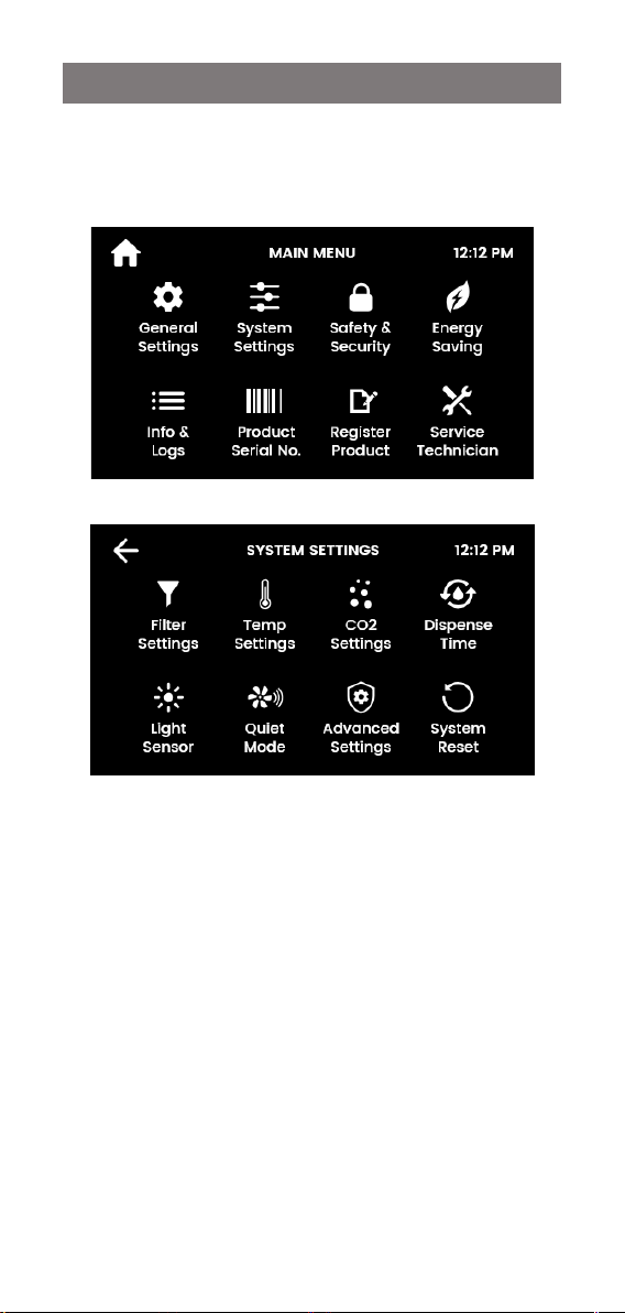
3.3 Main menu
Use the Main menu to configure your HydroTap and
access features and settings. Touch each icon to access
further options.
[ ]
3.4 General settings
Language
16
Units :
LANGUAGE 10:50
English
Metric
Imperial
806835 v1.07 09.22 G5 User guide
Page 17

SECTION 3: Command Centre Screen
Date and time
Touch the text boxes on the screen and then press + and to set the current date and time. Press the tick to confirm
and save.
06
DATE & TIME
Dec
:
10
50
2021
12:12 PM
Mon
24 hr
Time
Network
Connect to Wi Fi (available with optional Zip Assist Kit).
NETWORK 12:12
Zip Wi-Fi
Hotspot
Off Connected Registered
Wi-Fi
Network
Fault
relay
Network
Off Off
Cloud
Registration
LoRa
806835 v1.07 09.22 G5 User guide
17
Page 18
SECTION 3: Command Centre Screen
3.5 System settings
Configure your HydroTap to suit your needs.
Navigate to system settings screen for all system settings.
[ ]
18
806835 v1.07 09.22 G5 User guide
Page 19

SECTION 3: Command Centre Screen
3.5.1 Filter settings
FILTER SETTINGS 12:12 PM
Filter
Flush
Tank
Flush
Filter
Reset
Filter
Life
Filter flush
Use Filter flush during commissioning of a new installation,
and after every filter change.
See page 35 for filter change instructions.
Flush line tap
Open filter door, uncoil flush line.
Direct flush line into bucket.
Open flush line tap.
806835 v1.07 09.22 G5 User guide
Flush line tap open
19
Page 20

SECTION 3: Command Centre Screen
Start flush.
Approximately 10L of water will
flow, for 2 minutes.
FILTER FLUSH
RUNNING.....
Water is now being flushed through the filter.
This process is automatic and will take 2 minutes.
Press pause to pause filter flush.
The screen will show the filter has
been flushed.
Close the flush line tap, return the
flush line to the filter compartment
and close door.
Reset the filter counter (see page 19).
20
12:12 PM
| |
Flush line tap closed
806835 v1.07 09.22 G5 User guide
Page 21

SECTION 3: Command Centre Screen
Filter reset
Reset the filter counters after filter replacement and flush.
FILTER RESET 12:12 PM
This will reset the usage counters for the chosen item.
Select an item and press reset to confirm.
Internal
filter
External
filter
Filter life
Select internal/external filter and edit the filter life (months
or litres) and actual usage (days or litres).
When usage exceeds the filter life, the tap lights and
screen will indicate to change the water filter.
Default internal water filter life:
• Residential: 12 months or 4000L
• Commercial: 6 months or 6000L.
INTERNAL FILTER LIFE 12:12 PM
Life (months)
12 000
Life (litres)
04000 000
Usage (days)
Usage (litres)
806835 v1.07 09.22 G5 User guide
21
Page 22

SECTION 3: Command Centre Screen
3.5.2 Temperature settings
Boiling / Chilled set point
Adjust as required.
COLD/HOT SETPOINT 12:12 PM
Chill Set Point
°C
3-6
Boiling Set Point
°C
98
Chilled models
Default chill set point: 5-9ºC Commercial, 6-10ºC Residential.
Scroll to select alternatives.
Sparkling models
Chill set point: 3-6ºC Commercial, 3-7ºC Residential.
This set temperature is fixed, for sparkling optimisation.
Boiling models
Default set point: 98ºC Set point range: 68-100ºC.
Operation: Within 1-2ºC of set point.
Note: Boiling water delivery rate will be affected with a
higher temperature setting. Up to 6% less energy in standby
is consumed with a 98ºC set point, rather than 100ºC.
A warning icon will appear when setting boiling set point
temperatures that are subject to pump cavitation.
22
806835 v1.07 09.22 G5 User guide
Page 23

SECTION 3: Command Centre Screen
Boiling calibration
Take care during boiling calibration as hot
!
External Booster
For selected commercial Boiling models, an external
booster is supplied or may be purchased as an upgrade to
increase Boiling capacity.
steam may vent from the tap spout.
On start-up, the HydroTap self-calibrates, or
go to this menu to recalibrate.
Calibration will take around 10 minutes.
Ensure the correct selection is made, for optimum
performance.
806835 v1.07 09.22 G5 User guide
23
Page 24

SECTION 3: Command Centre Screen
3.5.3 CO settings
CO2 SETTINGS 12:12 PM
Purge
CO2
CO2
Reset
CO2
Life
CO purge
Purge the gas lines when fitting a new CO gas cylinder.
Press the green start icon. The purge runs for 30 seconds.
Water may be dispensed before CO gas escapes from the
tap. The purge process stops automatically.
12:12 PMPURGE WATER WITH CO2
This process removes water from the sparkling
chamber when a new CO2 bottle is installed.
This is an automatic process that will take 30 seconds.
INFO
CO reset
After fitting a new CO cylinder, reset the CO counter.
24
806835 v1.07 09.22 G5 User guide
Page 25

SECTION 3: Command Centre Screen
CO life
CO life may be adjusted by months or litres. The Home
screen displays a warning when the CO level reaches 20%
(see page 14).
CO life defaults to grams absorbed. Months of use
may also be selected to trigger a reminder to prepare a
replacement CO cylinder.
Usage is dependent on CO absorption, settings on the
HydroTap, and leak-free installation.
CO cylinders are available in two sizes:
• 1.2kg (approx. 180-200L) for residential or commercial
(UK).
• 2.64kg (approx. 400-460L) for commercial (not available
in UK).
806835 v1.07 09.22 G5 User guide
25
Page 26

SECTION 3: Command Centre Screen
3.5.4 Dispense times
Set the “bottle fill” dispense time for each water type.
Minimum dispense time: 5 seconds.
Maximum dispense time: 15 seconds (default).
3.5.5 Light sensor
Follow the on screen instructions.
Ensure the ambient light in the room is typical for
operating conditions.
The lights on the tap will flash to confirm calibration.
When the room is darkened below the calibrated light
level, the tap lights will turn OFF after 30 seconds. Energy
saving modes may occur. Refer to section 3.7 (page 31).
LIGHT SENSOR 12:12 PM
This will calibrate the light sensor which will allow the
system to go to sleep when it is dark.
Before we start, the room should be in a typical
Remove any object away from the tap.
26
CALIBRATION
ambient lit environment.
806835 v1.07 09.22 G5 User guide
Page 27

SECTION 3: Command Centre Screen
3.5.6 Quiet mode
Lowering the fan speed can reduce noise. Increasing it
may improve chilling performance.
Residential models: 75% / 100% / Auto (default).
Commercial models: 100% (default) / Auto.
3.5.7 Advanced settings 1
12:12 PMADVANCED SETTINGS 1
Periodic Pulse Reduced Cavitation Mode
Hot setpoint must be < 98°C to disable
Pre-pulse Reduced Cavitation Mode
Adds slight delay to boiling dispense
Power Pulsing Mode
Hot setpoint must be < 98.5°C to disable
Periodic Pulse Reduced Cavitation Mode
Sends two electric pulses every 5 minutes to the pump.
This prevents the build-up of air bubbles inside the pump
to ensure an even flow of hot water at the tap.
Pre-Pulse Reduced Cavitation Mode
Pulses immediately before boiling dispense to prevent the
build-up of air bubbles inside the pump and ensure an even
flow of hot water at the tap. There will be a 150 millisecond
delay before water is dispensed.
Power Pulsing Mode
Applies a closer tolerance to the set temperature, to
ensure hot water is maintained as closely as possible to the
set point.
806835 v1.07 09.22 G5 User guide
27
Page 28

SECTION 3: Command Centre Screen
3.5.8 Advanced settings 2 (Wave Tap only)
12:12 PMADVANCED SETTINGS 2
Wave Tap Sensor Demister Mode
Allows Control of Heating of Wave Tap
Wave Tap Lock Mode
Dual Sensors Required for Chilled/Sparkling
Wave Tap Sensor Demister Mode
• Enabled (default): activates the Wave Tap internal
heater to prevent its sensors from being affected by
condensation from steam.
• Disabled: choose this option to conserve a small amount
of power.
Wave Tap Lock Mode
• Disabled (default): Chilled or sparkling water can be
dispensed by activating the corresponding sensor.
• Enabled: in addition to the chilled or sparkling sensor,
the rear sensor must also be activated in order to
dispense chilled or sparkling water. This is useful to
prevent false activation if a highly reflective surface is
present (such as high-visibility reflective tape). Note:
Bottle fill is disabled.
3.5.9 System restart
Touch the top circle, then the bottom circle to power
down and restart the system. Use this function to reset
faults or to reset the settings access password.
28
806835 v1.07 09.22 G5 User guide
Page 29

SECTION 3: Command Centre Screen
3.6 Safety & security
3.6.1 Boiling safety
(Not applicable to Touch-Free Wave Tap)
Boiling safety lock
Use the safety button to dispense hot water
Hot isolation (additional boiling safety)
3 slow safety button presses required
prior to dispensing
12:12 PMBOILING SAFETY
Boiling safety lock
• Enabled (default): safety button must be touched/
tapped in order to dispense boiling water.
• Disabled: boiling water can be dispensed without the
need to touch/tap the safety button.
Hot isolation
3 slow safety button presses are required prior to
dispensing.
806835 v1.07 09.22 G5 User guide
29
Page 30

SECTION 3: Command Centre Screen
3.6.2 Passcode protect
Activate passcode protection to limit access to certain
settings. Users will be prompted for this passcode when
attempting to access settings.
Create a 4-digit passcode and re-enter, as prompted.
The passcode will be deactivated if the HydroTap is reset
(powered off and on again).
30
806835 v1.07 09.22 G5 User guide
Page 31

SECTION 3: Command Centre Screen
3.7 Energy saving
3.7.1 Sleep mode
• Disabled (default).
• Enabled: Any attempt to dispense water will bring the
HydroTap out of sleep mode. Allow sufficient time for
the water to reach the set temperature.
Sleep when...
Select from: It gets dark / Not used in 2 hours / Both
Recalibrate the light sensor after selecting sleep when “it
gets dark”. Ensure the ambient light is typical for operating
conditions (see page 26).
SLEEP WHEN 12:12 PM
806835 v1.07 09.22 G5 User guide
It gets
dark
Not used
in 2 hours
31
Page 32

SECTION 3: Command Centre Screen
When sleeping
Choose between the following modes:
• Keep hot water at 68°C (default). Chilled water will be
kept at setpoint, for chilled models.
• Turn system OFF: boiling and chilled water will be OFF.
3.7.2 On/Off Timer
The option that is in effect is highlighted.
When OFF, the HydroTap will stop chilling and heating the
drinking water.
During OFF mode, any attempt to dispense water will bring
the HydroTap back ON. Allow sufficient time for the water
to reach the set temperature.
After 30 minutes of non-use, the system will revert to the
On / Off setting.
Set Timer
The off/on timer can be set to the same time every day,
on a range of days (weekdays/weekends), or by individual
days.
12:12 PMSET TIMER
Everyday
Weekdays / Weekends
Individual days
32
806835 v1.07 09.22 G5 User guide
Page 33

SECTION 3: Command Centre Screen
12:12 PMENERGY USE
3.7.2 On/Off Timer continued
Select the day or range of days, then set the desired Off/
On times. Touch the tick to confirm and save.
12:12 PMSET TIMER
Mon Tue Wed Thu Fri Sat Sun
Off at On at
:
0023
:
0023
3.7.3 Energy Use
Track energy usage of your HydroTap by viewing the total
energy consumed and the energy consumed since the last
energy use reset.
12:12 PMENERGY USE
Total (kWh)
00000.0
Last Period (kWh)
000.0
Date of Reset
01/01/2020
806835 v1.07 09.22 G5 User guide
The bottom right button is used to reset the
‘last period’ usage counter.
33
Page 34

SECTION 3: Command Centre Screen
3.8 Info & logs
INFO & LOGS 12:12 PM
Filter
Logs
!
System
Faults
!
Recent
Faults
i
About
System
Filter Logs, System Faults, Recent Faults
View the filter reset history, current and recent fault history.
About System
View the system information.
ABOUT SYSTEM 12:12 PM
Title Info
Module:
App. revision:
Serial No:
Product No:
Calibration:
50L Filtered:
Wi-Fi:
MAC Address:
BCS100
017-H5v0.1.xx
0000000000000
H500xx000US
N/A
N/A
BS 0.00 FW 0.00
00:00:00:00:00:00
34
806835 v1.07 09.22 G5 User guide
Page 35

SECTION 4: User maintenance
4.1 Changing the internal filter
The tap and screen will indicate that a filter needs to be
changed.
Depending on local water quality conditions and usage,
the filter may require changing before the filter change
indication is shown. You may also need to replace the filter
if you notice an increase in chlorine, taste or odour.
Open filter door.
Remove
Rotate
Pull
Remove old filter.
!
Place a cloth or towel under the filter cartridge before
removing. Water will drip as the cartridge is removed.
Unpack replacement cartridge and remove sanitary cap.
Write today’s date on the label.
806835 v1.07 09.22 G5 User guide
35
Page 36

SECTION 4: User maintenance
Moisten connector o-rings.
Insert
Rotate
Push up
Fit new filter.
Initiate the filter flush programme by scrolling through the
menu screen (see page 19).
Clean up and dispose of old cartridge and packaging.
If the HydroTap is switched off for a long period of time
(e.g. more than a weekend), run water through the chilled
water outlet for at least 60 seconds before consumption.
36
806835 v1.07 09.22 G5 User guide
Page 37

SECTION 4: User maintenance
4.2 Air inlet filter maintenance
Remove and clean quarterly.
Rinse off with tap water.
Gently dry with a cloth or towel.
Maintain at least a 50mm air gap in front of the air inlet
screen at all times.
Take care to keep the air inlet clear of blockage.
806835 v1.07 09.22 G5 User guide
37
Page 38

SECTION 4: User maintenance
!
4.3 Cleaning
To clean all taps, Command Centre and
ancillaries, wipe external surfaces with a gentle
cleaning agent or a damp cloth and then wipe
dry immediately with a clean, dry cloth.
Do not use strong, corrosive, spray or abrasive
cleaners.
!
Command Centres must never be located near
or cleaned with water jets.
For the Touch-Free Wave Tap:
Do not use abrasives to clean the sensor lenses
at the sides, top and rear of the Touch-Free
Wave Tap.
Do not use disinfectant sprays without wiping
dry afterwards.
This could cause permanent malfunction and
void warranty.
38
806835 v1.07 09.22 G5 User guide
Page 39

!
SECTION 4: User maintenance
I
I
I
I
I
I
I
I
I
I
I
I
I
I
I
I
I
I
I
I
I
I
I
I
I
I
I
I
I
I
I
I
I
I
I
I
I
I
I
I
I
I
I
I
I
I
I
I
I
I
I
I
I
I
I
I
I
I
I
I
I
I
I
I
I
I
I
I
I
I
I
I
I
I
I
I
I
I
I
I
I
I
I
I
I
I
I
I
I
I
I
I
I
I
I
I
I
I
I
I
I
I
I
I
I
I
I
I
I
I
I
I
I
I
I
I
I
I
I
I
I
I
I
I
I
I
I
I
I
I
I
I
I
I
I
I
I
I
I
I
I
I
I
I
I
I
I
I
I
I
I
I
I
I
I
I
I
I
I
I
I
I
I
I
I
I
I
I
I
I
I
I
I
I
I
I
I
I
I
I
I
I
I
I
I
I
I
I
I
I
I
I
I
I
I
I
I
I
I
I
I
I
I
I
I
I
I
I
I
I
I
I
I
I
I
I
I
I
I
I
I
I
I
I
I
I
I
I
I
I
I
I
4.4 CO cylinder and regulator
Significant concentrations of CO gas can
cause harm.
To prevent leaks, read and use the
instructions and safety documents provided
with the replacement cylinder, together with
these instructions.
Components
Cylinder valve
I
I
I
I
I
I
I
I
I
I
I
I
I
I
I
I
I
I
I
I
I
I
I
I
I
I
I
I
I
I
I
I
I
I
I
Hook and loop strap
I
I
I
I
I
I
I
I
I
I
I
I
I
I
I
I
I
I
I
I
I
I
I
Hose
and bracket
Regulator
Regulator to
cylinder
adaptor
I
I
I
I
I
I
I
I
I
I
I
I
I
I
I
I
I
I
I
I
I
I
I
I
I
I
I
I
I
I
I
I
I
I
I
I
I
I
I
I
I
I
I
I
I
I
I
I
I
I
I
I
I
I
I
I
I
I
Cylinder
Non-adjustable 1.2kg cylinder regulator
Non-adjustable
regulator
806835 v1.07 09.22 G5 User guide
1.2kg cylinder2.64kg cylinder
39
Page 40

I
I
I
I
I
I
I
I
I
I
I
I
I
I
I
I
I
I
I
I
I
I
I
I
I
I
I
I
I
I
I
I
I
I
I
I
I
I
I
I
I
I
I
I
I
I
I
I
I
I
I
I
I
I
I
I
I
I
I
I
I
I
I
I
I
I
I
I
I
I
I
I
I
I
I
I
I
I
I
I
I
I
I
I
I
I
I
I
I
I
I
I
I
I
I
I
I
I
I
I
I
I
I
I
I
I
I
I
I
I
I
I
I
I
I
I
!
SECTION 4: User maintenance
Universal G5 CO regulator
Cylinder pressure
Outlet
pressure
Set to
3.0 bar
Regulator
control
knob
Cylinder
connection
1.2kg cylinder non-adjustable regulator
Regulator control
knob
Braided hose
connection
Gas hose
connection
Cylinder
connection
40
806835 v1.07 09.22 G5 User guide
Page 41
SECTION 4: User maintenance
I
I
I
I
I
I
I
I
I
I
I
I
I
I
I
I
I
I
I
I
I
I
I
I
I
I
I
I
I
I
I
I
I
I
I
I
I
I
I
I
I
I
I
I
I
I
I
I
I
I
I
I
I
I
I
I
I
I
I
I
I
I
I
I
I
I
I
I
I
I
I
I
I
I
I
I
I
I
I
I
I
I
I
I
I
I
I
I
I
I
I
I
I
I
I
I
I
I
I
I
I
I
I
I
I
I
I
I
I
I
I
I
I
I
I
I
I
I
I
I
I
I
I
I
I
I
I
I
I
I
I
I
I
I
I
I
I
I
I
I
I
I
I
I
I
I
I
I
I
I
I
I
I
I
I
I
I
I
I
I
I
I
I
I
I
I
I
I
I
I
I
I
I
I
I
I
I
I
I
I
I
I
I
I
I
I
I
I
I
I
I
I
I
I
I
I
I
I
I
I
I
I
I
I
I
I
I
I
I
I
I
I
I
I
I
I
I
I
I
I
I
I
I
I
I
I
I
I
I
I
I
I
I
I
I
I
I
I
I
I
I
I
I
I
I
I
I
I
I
I
I
I
I
I
I
I
I
I
I
I
I
I
I
I
I
I
I
I
I
I
I
I
I
I
I
I
I
I
I
I
I
I
I
I
I
I
I
I
I
I
I
I
I
I
I
I
I
I
I
I
I
I
I
I
I
I
I
I
I
I
I
I
I
I
I
I
I
I
I
I
I
I
I
I
I
I
I
I
I
I
I
I
I
I
I
I
I
I
I
I
I
I
I
I
I
I
I
I
I
I
I
I
I
I
I
I
I
I
I
I
I
I
I
I
I
I
I
I
I
I
I
I
I
I
I
I
I
I
I
I
I
I
I
I
I
I
I
I
I
I
I
I
I
I
I
I
I
I
I
I
I
I
I
I
I
I
I
I
I
I
I
I
I
I
I
I
I
I
I
I
I
I
I
I
I
I
I
I
I
I
I
I
I
I
I
I
I
I
I
I
I
I
I
I
I
I
I
I
I
I
I
I
I
I
I
I
I
I
I
I
I
I
I
I
I
I
I
I
I
I
I
I
I
I
I
I
I
I
I
I
I
I
I
I
I
I
I
I
I
I
I
I
I
I
I
I
I
I
I
I
I
I
I
I
I
I
I
I
I
I
I
I
I
I
I
I
I
I
I
I
I
I
I
I
I
I
I
I
I
I
I
I
I
I
I
I
I
I
I
I
I
I
I
I
I
I
I
I
I
I
I
I
I
I
I
I
I
I
I
I
I
I
I
I
I
I
I
I
I
I
I
I
I
I
I
I
I
I
I
I
I
I
I
I
I
I
I
I
I
I
I
I
I
I
I
I
I
I
I
I
I
I
I
I
I
I
I
I
I
I
I
I
I
I
I
I
I
I
I
I
I
I
I
I
I
I
I
I
I
I
I
I
I
I
I
I
I
I
I
I
I
I
I
I
I
I
I
I
I
I
I
I
I
I
I
I
I
I
I
I
I
I
I
I
I
I
I
I
I
I
I
I
I
I
I
I
I
I
I
I
I
I
I
I
I
I
I
I
I
I
I
I
I
I
I
I
I
I
I
I
I
I
I
I
I
I
I
I
I
I
I
I
I
I
I
I
I
I
I
I
I
I
I
I
I
I
I
I
I
I
I
I
I
I
I
I
I
I
I
I
I
I
I
I
I
I
I
I
I
I
I
I
I
I
I
I
I
I
I
I
I
I
I
I
I
I
I
I
I
I
I
I
I
I
I
I
I
I
I
I
I
I
I
I
I
I
I
I
I
I
I
I
I
I
I
I
I
I
I
I
I
I
I
I
I
I
I
I
I
I
I
I
I
I
I
I
I
I
I
I
I
I
I
I
I
I
I
I
I
I
I
I
I
I
I
I
I
I
I
I
I
I
I
I
I
I
I
I
I
I
I
I
I
I
I
I
I
I
I
I
I
I
I
I
I
I
I
I
I
I
I
I
I
I
I
I
I
I
I
I
I
I
I
I
I
I
I
I
I
I
I
I
I
I
I
I
I
I
I
I
I
I
I
I
I
I
I
I
I
I
I
I
I
I
I
I
I
I
I
I
I
I
I
I
I
I
I
I
I
I
I
I
I
I
I
I
I
I
I
I
I
I
I
I
I
I
I
I
I
I
I
I
I
I
I
I
I
I
I
I
I
I
I
I
I
I
I
I
I
I
I
I
I
I
I
I
I
I
I
I
I
I
I
I
I
I
I
I
I
I
I
I
I
I
I
I
I
I
I
I
I
I
I
I
I
I
I
I
I
I
I
I
I
I
I
I
I
I
I
I
I
I
I
I
I
I
I
I
I
I
I
I
I
I
I
I
I
I
I
I
I
I
I
I
I
I
I
I
I
I
I
I
I
I
I
I
I
I
I
I
I
I
I
I
I
I
I
I
I
I
I
I
I
I
I
I
I
I
I
I
I
I
I
I
I
I
I
I
I
I
I
I
I
I
I
I
I
I
I
I
I
I
I
I
I
I
I
I
I
I
I
I
I
I
I
I
I
I
I
I
I
I
I
I
I
I
I
I
I
I
I
I
I
I
I
I
I
I
I
I
I
I
I
I
I
I
I
I
I
I
I
I
I
I
I
I
I
I
I
I
I
I
I
I
I
I
I
I
I
I
I
I
I
I
I
I
I
I
I
I
I
I
I
I
I
I
I
I
I
I
I
I
I
I
I
I
I
I
I
I
I
I
I
I
I
I
I
I
I
I
I
I
I
I
I
I
I
I
I
I
I
I
I
I
I
I
I
I
I
I
I
I
I
I
I
I
I
I
I
I
I
I
I
I
I
I
I
I
I
I
I
I
I
I
I
I
I
I
I
I
I
I
I
I
I
I
I
I
I
I
I
I
I
I
I
I
I
I
I
I
I
I
I
I
I
I
I
I
I
I
I
I
I
I
I
I
I
I
I
I
I
I
I
I
I
I
I
I
I
I
I
I
I
I
I
I
I
I
I
I
I
I
I
I
I
I
I
I
I
I
I
I
I
I
I
I
I
I
I
I
I
I
I
I
I
I
I
I
I
I
I
I
I
I
I
I
Regulator
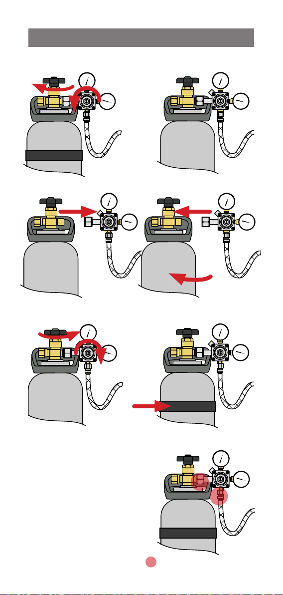
4.4.1 Changing the 2.64kg CO cylinder
I
I
I
I
I
I
I
I
I
I
I
I
I
I
1
I
I
I
I
I
I
I
I
I
I
I
I
I
I
I
I
I
I
I
I
I
I
I
I
I
I
I
I
I
I
I
I
I
I
I
I
I
I
I
I
I
I
I
I
2
I
I
I
I
I
I
I
I
I
I
I
I
I
I
I
I
I
I
I
I
I
I
I
I
I
I
I
I
I
I
I
I
I
I
I
I
I
I
I
I
I
I
I
I
I
I
I
I
I
I
I
I
I
I
I
I
I
I
Turn off cylinder valve & regulator.
I
I
I
I
I
I
I
I
I
I
I
I
I
I
I
I
I
I
I
3 4
Unscrew regulator
connection.
5
Turn on the cylinder valve
I
I
I
I
I
I
I
I
I
I
I
I
I
I
I
I
I
I
I
I
I
I
I
I
I
I
I
I
I
I
I
I
I
I
I
I
I
I
I
I
I
I
I
I
I
I
I
I
I
I
I
I
I
I
I
I
I
I
I
I
I
I
I
I
I
I
I
I
I
I
I
I
I
I
I
I
I
I
I
I
I
I
I
I
I
I
I
I
I
I
I
I
I
I
I
I
I
Replace cylinder and refit
regulator.
6
Strap in place.
Adjust outlet pressure 3.0 bar.
7
Test for leaks by brushing
with soapy water and looking
for bubbles.
Reseal if leaking, or call Zip for
advice and assistance.
8
Purge, reset and set the CO
life, (see page 24).
806835 v1.07 09.22 G5 User guide
2
Unstrap.
I
I
I
I
I
I
I
I
I
I
I
I
I
I
I
I
I
I
I
I
I
I
I
I
I
I
I
I
I
I
I
I
I
I
I
I
I
I
I
I
I
I
I
I
I
I
I
I
I
I
I
I
I
I
I
I
I
I
I
I
I
I
I
I
I
I
I
I
I
I
I
I
I
I
I
I
I
I
I
I
I
I
I
I
I
I
I
I
I
I
I
I
I
I
I
I
I
I
I
I
I
I
I
I
I
I
I
I
I
I
I
I
I
I
I
I
I
I
I
I
I
I
I
I
I
I
I
I
I
I
I
I
I
I
I
I
I
I
Test for leaks in these areas
I
I
I
I
I
I
I
I
I
I
I
I
I
I
I
I
I
I
I
I
I
I
I
I
I
I
I
I
I
I
I
I
I
I
I
I
41
Page 42

I
I
I
I
I
I
I
I
I
I
I
I
I
I
I
I
I
I
I
I
I
I
I
I
I
I
I
I
I
I
I
I
I
I
I
I
I
I
I
I
I
I
I
I
I
I
I
I
I
I
I
I
I
I
I
I
I
I
I
I
I
I
I
I
I
I
I
I
I
I
I
I
I
I
I
I
I
I
I
I
I
I
I
I
I
I
I
I
I
I
I
I
I
I
I
I
I
I
I
I
I
I
I
I
I
I
I
I
I
I
I
I
I
I
I
I
I
I
I
I
I
I
I
I
I
I
I
I
I
I
I
I
I
I
I
I
I
I
I
I
I
I
I
I
I
I
I
I
I
I
I
I
I
I
I
I
I
I
I
I
I
I
I
I
I
I
I
I
I
I
I
I
I
I
SECTION 4: User maintenance
I
I
I
I
I
I
I
I
I
I
I
I
I
I
I
I
I
I
I
I
I
I
I
I
I
I
I
I
I
I
I
I
I
I
I
I
I
I
I
I
I
I
I
I
I
I
I
I
I
I
I
I
I
I
I
I
I
I
I
I
I
I
I
I
I
I
I
I
I
I
I
I
I
I
I
I
I
I
I
I
I
I
I
I
I
I
I
I
I
I
I
I
I
I
I
I
I
I
I
I
I
I
I
I
I
I
I
I
I
I
I
I
I
I
I
I
I
I
I
I
I
I
I
I
I
I
I
I
I
I
I
I
I
I
I
I
I
I
I
I
I
I
I
I
I
I
I
I
I
I
I
I
I
I
I
I
I
I
I
I
I
I
I
I
I
I
I
I
I
I
I
I
I
I
I
I
I
I
I
I
I
I
I
I
I
I
I
I
I
I
I
I
I
I
I
I
I
I
I
I
I
I
I
I
I
I
I
I
I
I
I
I
I
I
I
I
I
I
I
I
I
I
I
I
I
I
I
I
I
I
I
I
I
I
I
I
I
I
I
I
I
I
I
I
I
I
I
I
I
I
I
I
I
I
I
I
I
I
I
I
I
I
I
I
I
I
I
I
I
I
I
I
I
I
I
I
I
I
I
I
I
I
I
I
I
I
I
I
I
I
I
I
I
I
I
I
I
I
I
I
I
I
I
I
I
I
I
I
I
I
I
I
I
I
I
I
I
I
I
I
I
I
I
I
I
I
I
I
I
I
I
I
I
I
I
I
I
I
I
I
I
I
I
I
I
I
I
I
I
I
I
I
I
I
I
I
I
I
I
I
I
I
I
I
I
I
I
I
I
I
I
I
I
I
I
I
I
I
I
I
I
I
I
I
I
I
I
I
I
I
I
I
I
I
I
I
I
I
I
I
I
I
I
I
I
I
I
I
I
I
I
I
I
I
I
I
I
I
I
I
I
I
I
I
I
I
I
I
I
I
I
I
I
I
I
I
I
I
I
I
I
I
I
I
I
I
I
I
I
I
I
I
I
I
I
I
I
I
I
I
I
I
I
I
Regulator
4.4.2 Changing the 1.2kg CO2 cylinder
Universal G5 regulator
1
I
I
I
I
I
I
I
I
I
I
I
I
I
I
I
I
I
I
I
I
I
I
I
I
I
I
I
I
I
I
I
I
I
I
I
I
I
I
I
I
I
I
I
I
I
I
I
I
I
I
I
I
I
I
I
I
I
I
2
I
I
I
I
I
I
I
I
I
I
I
I
I
I
I
I
I
I
I
I
I
I
I
I
I
I
I
I
I
I
I
I
I
I
I
I
I
I
I
I
I
I
I
I
I
I
I
I
I
I
I
I
I
I
I
I
I
I
Turn off regulator.
I
I
I
I
I
I
I
I
I
I
I
I
I
I
I
I
I
I
I
I
I
I
I
I
I
I
3
Unscrew regulator
connection.
5
I
I
I
I
I
I
I
I
I
I
I
I
I
I
I
I
I
I
I
I
I
I
I
I
I
I
I
I
I
I
I
I
I
I
I
I
I
I
I
I
I
I
I
I
I
I
I
I
I
I
I
I
I
I
I
I
I
I
I
I
I
I
I
I
I
I
I
I
I
I
I
I
I
I
I
I
I
I
I
I
I
I
I
I
I
I
I
I
I
I
3.0 bar.
7
Test for leaks by brushing
with soapy water and looking
for bubbles.
Reseal if leaking, or call Zip for
advice and assistance.
8
Purge, reset and set the CO2
life, (see page 24).
42
Unstrap.
I
I
I
I
I
I
I
I
I
I
I
I
I
I
I
I
I
I
I
I
I
I
I
I
I
I
4
I
I
I
I
I
I
I
I
I
I
I
I
I
I
I
I
I
I
I
I
I
I
I
I
I
I
I
I
I
I
I
I
Replace cylinder and refit
regulator inc. adaptor.
6
I
I
I
I
I
I
I
I
I
I
I
I
I
I
I
I
I
I
I
I
I
I
I
I
I
I
I
I
I
I
I
I
I
I
I
I
I
I
I
I
I
I
I
I
I
I
I
I
I
I
I
I
I
I
I
I
I
I
Strap in place.Adjust outlet pressure
I
I
I
I
I
I
I
I
I
I
I
I
I
I
I
I
I
I
I
I
I
I
I
I
I
I
I
I
I
I
I
I
I
I
I
I
I
I
I
I
I
I
I
I
I
I
I
I
I
I
I
I
I
I
I
I
I
I
Test for leaks in these areas
806835 v1.07 09.22 G5 User guide
Page 43

SECTION 4: User maintenance
Non-adjustable regulator
1 2
Turn off regulator.
3
Unscrew regulator
connection.
5
valve.
7
Test for leaks by brushing
with soapy water and looking
for bubbles.
Reseal if leaking, or call Zip for
advice and assistance.
8
Purge, reset and set the CO2
life, (see page 24).
806835 v1.07 09.22 G5 User guide
Unstrap.
4
Replace cylinder and refit
regulator.
6
Strap in place.Turn ON regulator
Test for leaks in these areas
43
Page 44

Zip Water
ABN 46 000 578 727
67 - 77 Allingham Street, Condell Park, NSW 2200
Postal: Locked Bag 80, Bankstown 1885, Australia
(+612) 9796 3100 | Free Call (Aust): 1800 947 827
www.zipwater.com
AU02691
Zip Water UK
Trafalgar House
Rash’s Green, Dereham,
Norfolk NR19 1JG
0345 6 005 005
sales@zipindustries.co.uk
specify.zipwater.co.uk
As Zip policy is one of continuous product improvement, changes
to specifications may be made without prior notice. Images in this
booklet have been modified and may not be true representations
of the finished goods.
The terms “Zip” and “HydroTap” are registered trade marks of Zip
Heaters (Aust) Pty Ltd.
44
806835 v1.07 09.22 G5 User guide
 Loading...