

Page 1
Installation instructions & user manual
Zip
ChillTap
Filtered, chilled water on tap.
806143 - CW ChillTap UCCT 10.18 v1.03
1
Page 2

Table of contents
ChillTap Specifications
Before Installation ........................................................................................................................... 3
Warnings and Precautions .............................................................................................................. 3
Technical Specification ................................................................................................................... 4
Installation Requirements ............................................................................................................... 4
Installation Instructions
Tap installation ................................................................................................................................ 5
Ventilation ....................................................................................................................................... 6-7
Chiller installation ............................................................................................................................ 8-9
Commissioning................................................................................................................................ 9
Operation & Maintenance ............................................................................................................... 10
Troubleshooting .............................................................................................................................. 11
Cleaning .......................................................................................................................................... 11
End of Life Disposal ........................................................................................................................ 11
Contact Details ................................................................................................................................ 12
02 806143 - CW ChillTap UCCT 10.18 v1.03
Page 3
Before installation
A. Read the instructions.
B. Note: All fittings are supplied with the appliance kit except an isolation valve.
C. Check the water quality to determine if extra filtration will be required.
D. Check the appliance rating plate and ensure correct power is available for the appliance.
E. Check the underbench cupboard supporting the appliance is adequate for the total weight and size of the appliance.
F. Ensure a potable water supply connection with isolating valve inside the cupboard is within reach of the braided
hoses and positioned so that the connection point and the stop cock will not be obstructed when the undersink units
are installed.
Note:
All plumbing must comply with AS/NZS 3500.4.1 & AS/NZS 3500.4.2
All electrical must comply with AS/NZS 3000 wiring rules
All refrigeration must comply with AS/NZS 3350.2.24
The plumbing installation must be done in accordance with local Water Authority regulations and these Installation
Instructions.
As the installer, it is your responsibility to supply (if necessary) and install all valves as required by local regulations and
relevant standards.
WARNINGS AND PRECAUTIONS
1. Please read all Precautions, Installation Requirements, Installation Instructions before installing any Zip ChillTap.
2. Never attempt to install any Zip ChillTap without reading all of the applicable instructions.
3. All electrical connections must comply with current wiring rules.
4. This appliance is not designed for use by young children or infirm people without supervision.
5. Young children should be prevented from having access to ensure they are not able to use or play with the chiller.
6. This appliance must be earthed.
7. If the power supply cord is damaged it must be replaced by a Zip Service Provider or a qualified electrician.
8. The power cord and general power outlet must be in a safe and accessible position after installation.
9. Do not remove the cover of the appliance under any circumstances without first isolating the appliance from the
power supply.
10. This unit is designed for indoor use and must not be installed outdoors or exposed to the elements of nature.
11. This unit must not be positioned in an area that may be cleaned by a water jet.
12. This unit must not be cleaned by a water jet.
13. This appliance is not intended for use by persons (including children) with reduced physical, sensory or mental
capabilities, or lack of experience and knowledge, unless they have been given supervision or instruction
concerning use of the appliance by a person responsible for their safety. For products sold in Europe, this appliance
can be used by children aged from 8 years and above and persons with reduced physical, sensory or mental
capabilities or lack of experience and knowledge if they have been given supervision or instruction concerning
use of the appliance in a safe way and understand the hazards involved. Children should be supervised to ensure
that they do not play with the appliance. Cleaning and user maintenance shall not be made by children without
supervision.
14. This appliance is intended to be used in: staff kitchen areas in shops, offices and other working environments;
Farm houses and by clients in hotels, motels and other residential type environments; Bed and breakfast type
environments; Catering and similar non-retail applications.
15. The appliance must be placed in an upright position.
806143 - CW ChillTap UCCT 10.18 v1.03
03
Page 4
Technical specification
Model Water supplied
Power
Rating (kW)
Refrigerant
Dimensions
W x D x H (mm)
Dry Weight*
ChillTap 60 glass Chilled 0.3 R134a 280 x 475 x 335 25
ChillTap Extra 60 glass Chilled, Ambient 0.3 R134a 280 x 475 x 335 25
ChillTap 140 glass Chilled 0.3 R134a 280 x 475 x 335 25
ChillTap Extra 140 glass Chilled, Ambient 0.3 R134a 280 x 475 x 335 25
Note: The standard glass is 200 ml (7 oz).
* Add 4kg when lled with water.
Installation requirements
• Power supply 220-240V AC, 50Hz for connection via a 10 amp G.P.O.
• Operating temperatures 5ºC - 35ºC.
• External water pressure 150kPa - 700kPa (1.5 bar - 7 bar)
• Internal Pressure Limiting Valve: 500kPa
(kg)
Note: For best results, the recommended minimum static mains water pressure is 250kPa (2.5 bar).
Frost Protection
If this appliance is located where the ambient air temperature could fall below 5ºC when the heater is not in use,
do not turn off the appliance electrically. This safeguard does not offer the same protection to the connecting
pipework and fittings.
04 806143 - CW ChillTap UCCT 10.18 v1.03
Page 5

Installation instructions
Tap Installation
In addition to common tools, the following will be required:
O-RING
NUT
Blue and Red
tubes to Tee piece
which connects to
Vent Outlet.
White tube to
Chilled Outlet
Fig.1 ChillTap Standard / Heavy Duty
• 25mm (ChillTap Standard/Heavy Duty) OR 35mm (ChillTap Extra)
diameter sheet metal hole punch for sink tops (not supplied)
• 25mm (ChillTap Standard/Heavy Duty) OR 35mm (ChillTap Extra)
diameter hole saw for timber bench tops (not supplied)
Position the Tap
Warning: Do not reuse old hose-sets. The unit shall be
installed with the new hose-sets supplied. Hoses are
maximum 1000 mm in length.
Position and install the tap at the back of the sink or on the Font, where there
is a minimum 52 mm wide flat area within the draining area of the sink. Make
sure the selected position allows the tap spout to overhang the sink bowl.
Ensure the distance between the tap and the undersink unit does not exceed
the length of the supplied tubing.
ChillTap Standard/Heavy Duty (Fig.1)
Use a 25mm sheet metal punch or hole saw to create a neat hole without
burrs.
O-RING
WASHER
Blue tube to
Chilled Outlet
White tube to
Ambient Outlet
Fig.2 ChillTap Extra
LOWER
RUBBER
WASHER
NUT
Red tube to
Vent Outlet
Remove the large nut from the base of the tap, leaving the rubber sealing
ring (O-ring) in place.
Fit the tap and O-ring to the sink top, oriented so the operating lever is easily
accessible.
From under the sink, slide the nut over the tubes. Tighten the nut to secure
the tap firmly into place.
ChillTap Extra (Fig.2)
Use a 35mm sheet metal punch or hole saw to create a neat hole without
burrs.
Remove the large nut with the stainless steel and rubber washers from the
base of the tap, leaving the rubber sealing ring (O-ring) in place.
Fit the tap and O-ring to the sink top, oriented so the operating levers are
easily accessible.
From under the sink, slide first the rubber washer, and then the brass
washer, followed by the nut, over the tubes. Tighten the nut to secure the tap
firmly into place.
806143 - CW ChillTap UCCT 10.18 v1.03
05
Page 6

Installation instructions
Clearance
Envelope
Ventilation
When installing air flow ducts, the following tools will be required:
•
Jigsaw and 12 mm drill.
•
Keyhole or Wall Board saw.
Ventilation Requirements
IMPORTANT! Allow clearance of 50 mm around and 200 mm above the chiller unit.
Proper air circulation must be provided for the system to operate correctly. Both the top and the front of the chiller
must remain accessible for servicing.
Fit the 3 mm silicon door buffers to the inside edge of the cupboard door (Fig.3).
The vent kit supplied with the ChillTap must be installed. The vent kit ensures heat dissipation through forced convection. Air is drawn in through the front vent and expelled via the duct and outlet vent installed in the cupboard
kickboard.
Referring to Fig.3 and Fig.4, mark out and cut the vent holes. Fit the grilles and secure with screws.
3 mm
Buffer Pad
Clear Gap
550mm
50
mm
50
mm
Fig.3
Warm Air OUT
via kickboard
louvre
*100mm
Cool Air IN via
cabinet floor, front
vent grille
477
* Note: Inlet and outlet vents should be separated by a minimum of 100 mm, to avoid hot air recirculation.
06 806143 - CW ChillTap UCCT 10.18 v1.03
Page 7

Installation instructions
= =
max 43
314.00
12.00
12.00
285.00
12.00
5
326.00
A
A - KICKBOARD CUT-OUT
1.Drill 4 pilot holes Ø12 in corners
2.Finish cut-out using Jigsaw
and Keyhole or Wall Board saw
B - CABINET FLOOR
CUT-OUT
1.Drill two pilot holes Ø12
2.Finish cut-out using Jigsaw
C - CABINET FLOOR
CUT-OUT
1.Drill 4 pilot holes
Ø12 in corners
2.Finish cut-out using Jigsaw
and Keyhole or Wall Board saw
60.00
B
C
12.00
45.00
284
Note: Ensure that A and B are positioned at opposite
ends of the cabinet.
Fig.4
Additional ventilation
The following instructions are critical if the vent kit, as supplied, cannot be fitted.
If the vent kit cannot be used, or for high use applications where the cupboard space temperature is 35°C or higher, an
optional Vent Tray Kit or Exhaust Fan kit may be fitted. Contact your local service centre for more information.
• Vent tray part no. 93541 (optional accessory)
• Dual exhaust fan kit, part no. 93156 (optional accessory)
Vent tray Dual exhaust fan
806143 - CW ChillTap UCCT 10.18 v1.03
07
Page 8
Installation instructions
Chiller Installation
Place the chiller unit into the cupboard with the proposed outlet tap position as close as possible, to minimise the length of
tubing exposed between the chiller unit and the outlet tap. Arrange tubes in the most direct route between tap outlet and unit.
The tubing length is limited to 1000 mm.
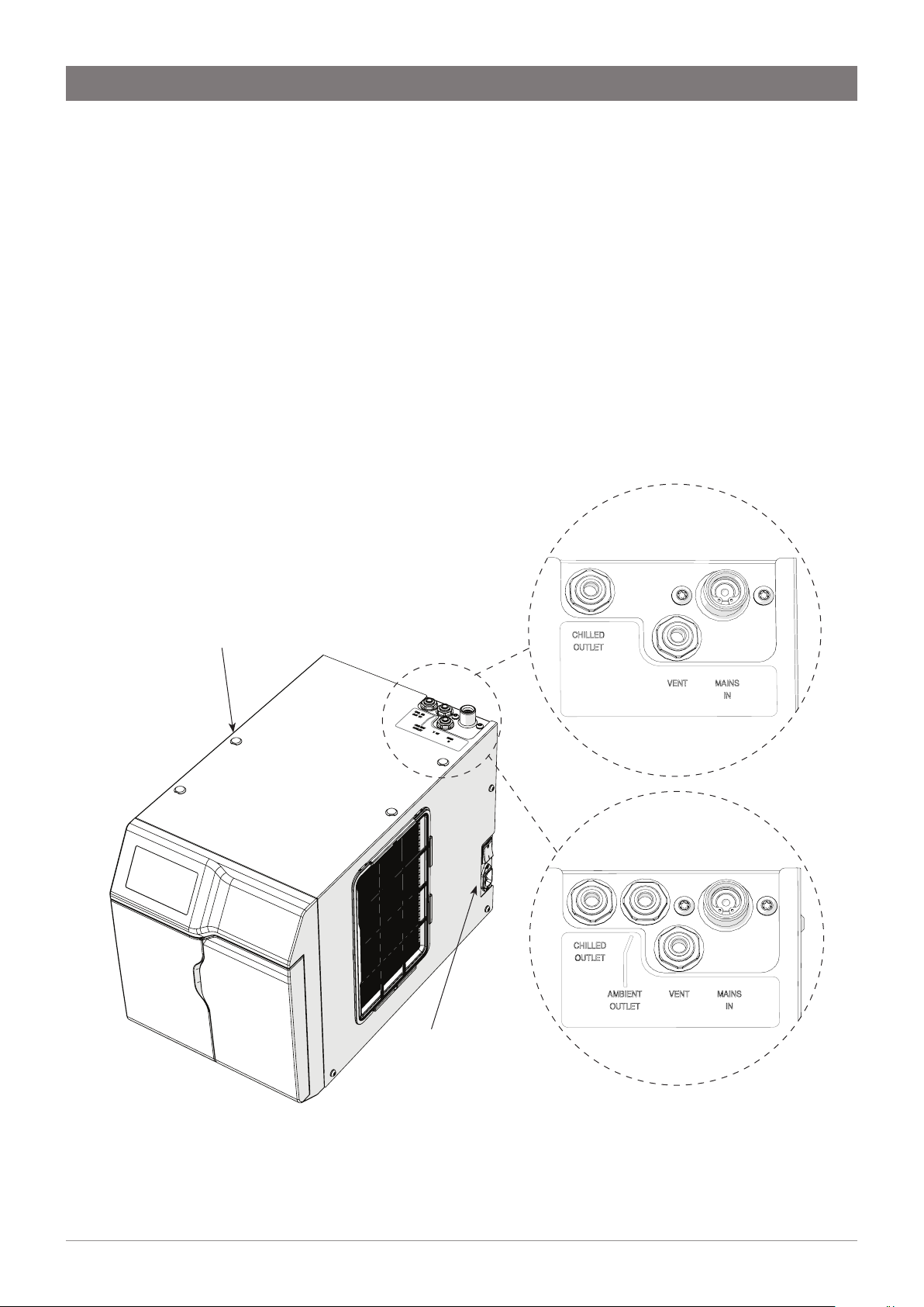
Mains Water Connection
Note: Install an isolation valve (not supplied) in the water supply line before the connection to the product.
Connect the braided hose to the isolation valve installed in the mains water supply line. For best results, the recommended
minimum static pressure is 250 kPa (2.5 bar).
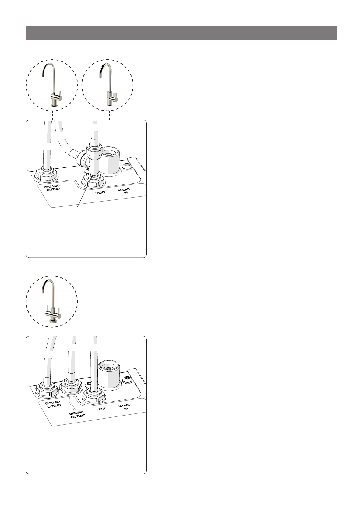
Connect the braided hose from the isolation valve to the top of the undersink unit, marked MAINS IN (see Fig.5).
Water Connection
for ChillTap
If caps are removed to allow lifting handles
to be installed during installation of the unit,
ensure they are retted when unit is in position.
Water Connection
for ChillTap Extra
Fig.5
08 806143 - CW ChillTap UCCT 10.18 v1.03
On / Off Switch
Page 9
Installation instructions
ChillTap Standard ChillTap Heavy Duty
RED
BLUE
WHITE
Tee piece
ChillTap Standard / Heavy Duty
Hose Connections
Note: To avoid water leaks, be careful not to damage the tubes.
The tube must not be kinked around a bend, as the tube may
contain water under pressure. If shortening the hoses, ensure
ends are cut clean and square.
1. Remove plugs from the outlet fittings on the top of
the undersink chiller unit by depressing the collet and
simultaneously pulling out the plug.
2. Measure and trim the three 1/4” coloured hoses from the carafe
tap to the outlet fittings on the top of the chiller unit. See Fig.6
and Fig.7.
3. Before making the connections, insulate the hoses with the
loose length of foam insulation. Trim the insulation to about
5-10mm shorter than the tube.
4. For correct hose connection, refer to Fig.6 for ChillTap
Standard and ChillTap Heavy Duty, and Fig.7 for ChillTap Extra.
Push each hose into the quick-release connector as far as it
will go (approx. 15 mm) to ensure a tight connection.
WHITE: Chilled
BLUE: Tee piece, side
RED: Tee piece, top
ChillTap Extra
WHITE RED
BLUE
Fig.6
Commissioning
Turn on the water supply to the unit, then rotate and hold the chilled
water or ambient water lever (ChillTap Extra). First air, then water
will flow from the tap. Allow the water to continue to flow for about
10 litres, which is required to activate the filter. Once this has been
done release the lever to turn off the water. The lever will spring
back to the upright position.
Connect the unit to the mains power supply and turn ON.
Switch ON the switch at the side of the undersink unit.
The compressor and fan will start, and will continue to run until
temperature is reached.
ChillTap Extra
WHITE: Ambient
BLUE: Chilled
RED: Vent
Fig.7
806143 - CW ChillTap UCCT 10.18 v1.03
09
Page 10
ROTATE
(ChillTap Extra)
Ambient water
(white)
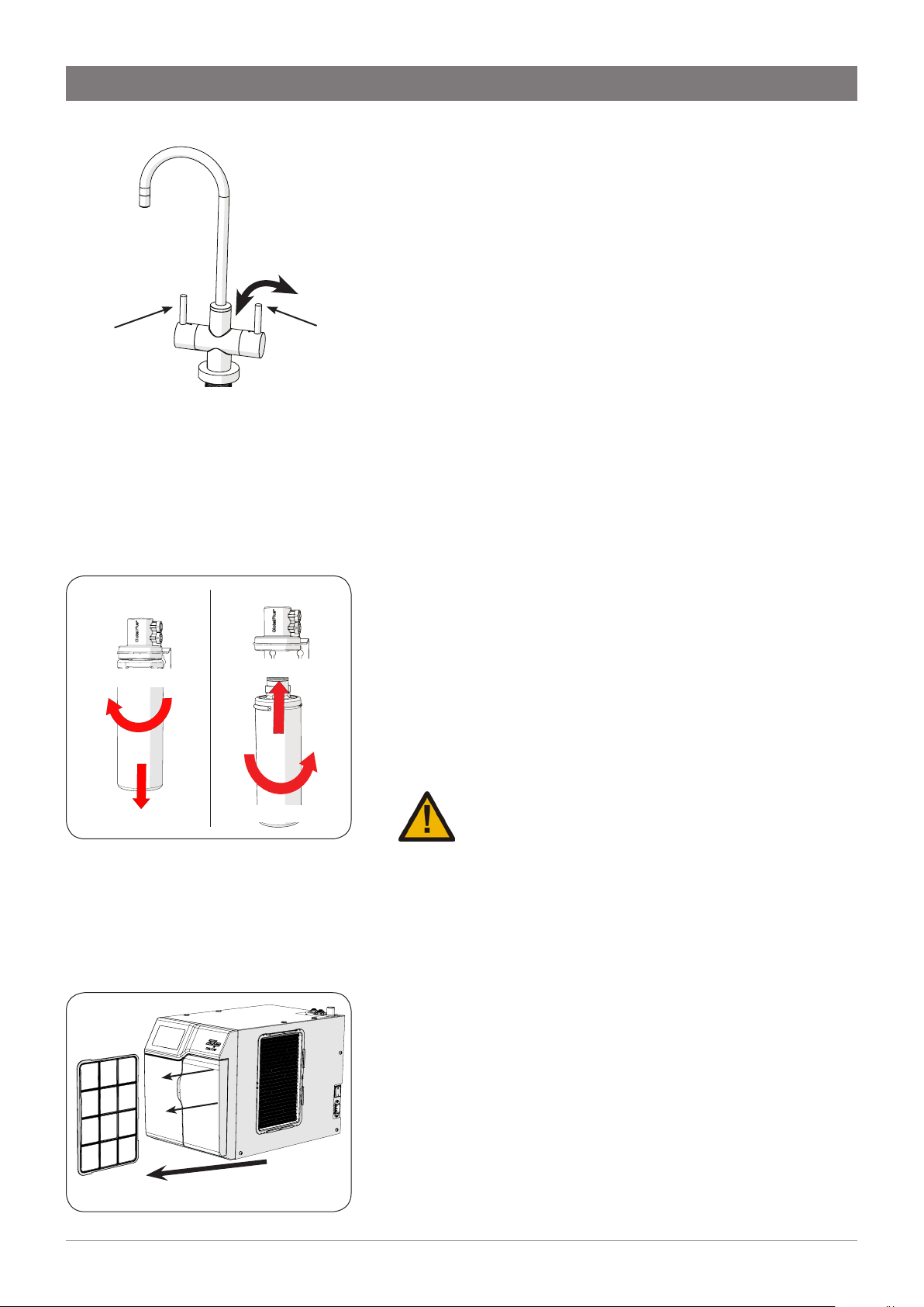
REMOVE FILTER INSERT FILTER
1. ROTATE
Chilled filtered
water (blue)
1. INSERT
Operation & Maintenance
Operation
To dispense chilled, filtered water, rotate the lever on the right hand
side of the carafe tap to a horizontal position. The lever will spring
back when released.
ChillTap Extra: Chilled still filtered water is dispensed using the
lever on the right hand side of the carafe tap (blue marking).
Ambient filtered water is dispensed using the lever on the left hand
side of the carafe tap (white marking).
The levers will spring back to the upright position and water flow
will stop, when released.
Water Filter
For safe operation, the filter cartridge should be replaced every
6-12 months, or earlier if you notice a persistent reduction in water
pressure from the appliance or an unpleasant taste or odour in the
water. To replace the water filter cartridge:
1. Turn off the water and power supply to the unit.
2. Turn on the chilled water lever (blue marking), to release the
water pressure in the unit. Once water has stopped running
from the tap, turn off the lever.
3. Turn the filter clockwise and gently pull the cartridge down.
The cartridge should release from the filter head. Dispose of
the filter cartridge responsibly. Clean any water that has pooled
below the filter head.
4. Fit a new filter by turning filter anti-clockwise and gently
pushing up. The filter will click or lock into place.
5. Turn on the water supply to the unit.
6. Turn on the chilled water tap. Allow 7.5 litres to flow from the outlet.
7. Turn off the chilled water tap.
8. Turn on the power supply to the unit.
2. PULL DOWN
Slide to remove
2. ROTATE
Warning: Not changing filtration cartridges when
required may cause the water to become biologically unsafe.
If the Zip ChillTap is switched off for a long period of time
(e.g. more than a weekend), run water through the chilled water
outlet for at least 5 minutes before consumption.
Use only a Zip filter to match that used with this ChillTap (if fitted).
Replacement filter cartridges can be obtained through plumbing
suppliers or directly from Zip.
Air Inlet Screen
The Zip ChillTap air inlet screen is located on the side of the under
sink unit. The screen needs to be inspected at least quarterly,
cleaned and replaced if damaged.
Remove the screen for cleaning by sliding it forward. Rinse off any
particles with tap water, then gently dry with a cloth or towel. Slide
the screen back into place.
Note: For best performance the unit should only be operated with a
clean air inlet screen, correctly fitted in place. Maintain at least a 50
mm air gap in front of the screen at all times. Take care not to allow
cloths or other soft materials to accidentally block the air inlet.
10 806143 - CW ChillTap UCCT 10.18 v1.03
Page 11

Troubleshooting
Prior to any fault finding, please ensure all water connections to the chiller are sound and that the incoming water supply is
turned on. Also ensure that all electrical connections to the chiller are secure and that the chiller has had adequate time to cool
down.
Call a licenced electrician, plumber, or Zip free call in Australia on 1800 460 222, for assistance, service, spare parts, or
enquiries.
Symptom Possible Cause Responsibility Solution
No water
Mains water not connected or
turned on
Water pressure regulator
failed
User or Service
Technician
Service Technician
Connect or turn on water supply.
Contact local Zip Service
Provider.
supplied
Contact local Zip Service
Provider.
Contact local Zip Service
Provider.
Restore power to the unit.
Contact local Zip Service
Provider.
Contact local Zip Service
Provider.
Contact local Zip Service
Provider.
Allow unit sufficient time to
recover.
Water not chilled
Unit frozen up Service Technician
Internal water leak Service Technician
No power
Thermostat faulty or out of
calibration.
User or Service
Technician
Service Technician
Insufficient cooling air flow
through the refrigeration
Service Technician
system
Refrigeration failure Service Technician
Rated chilled water capacity
has been exceeded
User
Cleaning
Never use strong, corrosive or abrasive cleaning materials. Stainless steel
surfaces will show scratches if an abrasive cleaning product is used.
Wipe clean the outer surfaces with a sponge or a soft cloth using a mild soap
and water.
The louvres on the sides of the chiller unit need to be kept free of dust and lint
to permit free flow of air through the vents. They should be checked regularly, at
least monthly, and dusted or vacuumed.
End of life disposal
In order to help preserve our environment we ask that you dispose of this product correctly. Please contact your
local city council for collection centre details.
806143 - CW ChillTap UCCT 10.18 v1.03
11
Page 12
Head Office
Zip Water (Aust) Pty. Ltd.
ABN 46 000 578 727
67-77 Allingham Street
Condell Park NSW 2200
Postal: Locked Bag 80
Bankstown 1885 Australia
www.zipwater.com
Telephone (02) 9796 3100
Sales Free Call: 1800 638 633
Service Free Call: 1800 460 222
The terms “Zip” and “ChillTap” are registered trade marks of Zip Water (Aust)
Pty Ltd. Zip products described in this publication are manufactured under
one or more patents and further patent applications are pending.
As Zip policy is one of continuous product improvement, changes to
specifications may be made without prior notice. Images in this booklet have
been modified and may not be true representations of the finished goods.
AU02691
WMKA21821
ATS5200.105
© 2018 Zip Water (Aust) Pty Ltd
12 806143 - CW ChillTap UCCT 10.18 v1.03
 Loading...