

Page 1
Electronically controlled instantaneous water heater
DEX: 27930 - 50 °C and 27931 - 60 °C models
Installation instructions
For 50 ºC models, the appliance delivers water not exceeding 50 ºC in accordance with AS3498.
Page 2
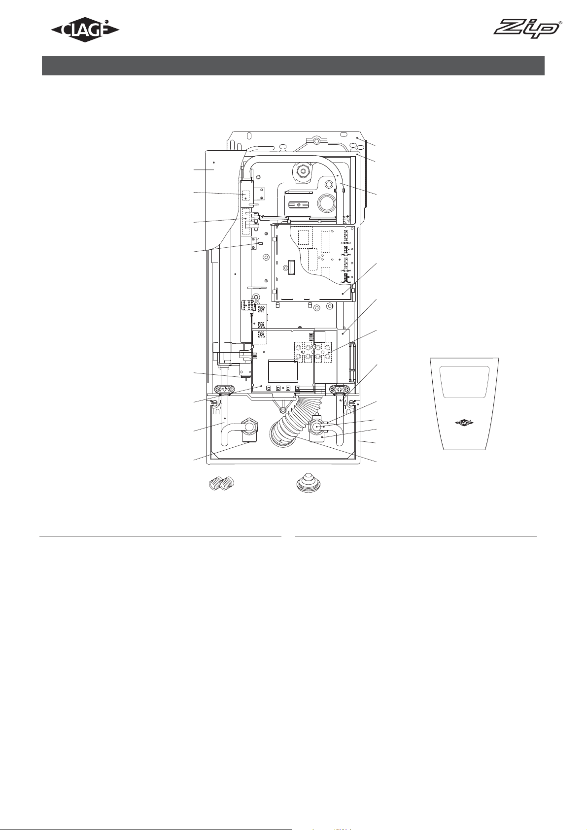
1. Overview
When ordering spare parts, please always specify the appliance model and serial number.
8
7
6
5
4
4
3
2
9
10
11
12
13
14
17
16
18
15
MADE IN GERMANY
1
Pos. Part.-No. Description
1 801097 Hot water connection
2 Outlet pipe
3 801107 DEX control panel
4 801098
5 801100
6 801101
DSX / DEX thermal sensor set 2.1
Flow sensor
Non-return valve
7 DEX hood
8 Wall bracket
9 Bottom part
10 DBX / DEX connecting pipe
11 801102 PCB cover 2.1
12 Control panel support
13 Connecting terminal
14 Inlet pipe
19
2021
22
Pos. Part.-No. Description
15 Frame
16 801108
17 801104
Flow limiter 8 l/min
Fine filter
18 801105 Cold water connection
19 Water splash protection sleeve
20 Grommet
21 Screw-in nipples 1/2”
22 801109 Faceplate
not shown:
23 801106 Set of small spare parts
24 Operating foil
Parts in Bold Type are available as Spare Parts.
Other parts are available on request.
2
Instructions for installer - 9120-34314 - DEX - 801048 - May 2013 v1.01
Page 3
Contents
1. Overview . . . . . . . . . . . . . . . . . . . . . . . . . . . . . . . . . . . . . . . . . . . . . . . . . . . . . . . . . . . . . . . . . . . . . . . . . . . . . . . . . . . . . . . . . . . . . . . 2
2. Environment and recycling . . . . . . . . . . . . . . . . . . . . . . . . . . . . . . . . . . . . . . . . . . . . . . . . . . . . . . . . . . . . . . . . . . . . . . . . . . . . . . . . . . 3
3. Safety instructions . . . . . . . . . . . . . . . . . . . . . . . . . . . . . . . . . . . . . . . . . . . . . . . . . . . . . . . . . . . . . . . . . . . . . . . . . . . . . . . . . . . . . . . .4
4. Technical specifications . . . . . . . . . . . . . . . . . . . . . . . . . . . . . . . . . . . . . . . . . . . . . . . . . . . . . . . . . . . . . . . . . . . . . . . . . . . . . . . . . . . . 5
5. Dimensions . . . . . . . . . . . . . . . . . . . . . . . . . . . . . . . . . . . . . . . . . . . . . . . . . . . . . . . . . . . . . . . . . . . . . . . . . . . . . . . . . . . . . . . . . . . . . . 5
6. Typical Installation . . . . . . . . . . . . . . . . . . . . . . . . . . . . . . . . . . . . . . . . . . . . . . . . . . . . . . . . . . . . . . . . . . . . . . . . . . . . . . . . . . . . . . . .6
7. Installation . . . . . . . . . . . . . . . . . . . . . . . . . . . . . . . . . . . . . . . . . . . . . . . . . . . . . . . . . . . . . . . . . . . . . . . . . . . . . . . . . . . . . . . . . . . . . . 8
Installation site . . . . . . . . . . . . . . . . . . . . . . . . . . . . . . . . . . . . . . . . . . . . . . . . . . . . . . . . . . . . . . . . . . . . . . . . . . . . . . . . . . . . . . . . . . . 8
Installating the wall bracket . . . . . . . . . . . . . . . . . . . . . . . . . . . . . . . . . . . . . . . . . . . . . . . . . . . . . . . . . . . . . . . . . . . . . . . . . . . . . . . . . 9
Installating the connection pipes . . . . . . . . . . . . . . . . . . . . . . . . . . . . . . . . . . . . . . . . . . . . . . . . . . . . . . . . . . . . . . . . . . . . . . . . . . . . . . 9
Installing the appliance . . . . . . . . . . . . . . . . . . . . . . . . . . . . . . . . . . . . . . . . . . . . . . . . . . . . . . . . . . . . . . . . . . . . . . . . . . . . . . . . . . . . 10
Surface mounted installation . . . . . . . . . . . . . . . . . . . . . . . . . . . . . . . . . . . . . . . . . . . . . . . . . . . . . . . . . . . . . . . . . . . . . . . . . . . . . . . . 11
Electrical connection . . . . . . . . . . . . . . . . . . . . . . . . . . . . . . . . . . . . . . . . . . . . . . . . . . . . . . . . . . . . . . . . . . . . . . . . . . . . . . . . . . . . . .11
Electrical connection from below . . . . . . . . . . . . . . . . . . . . . . . . . . . . . . . . . . . . . . . . . . . . . . . . . . . . . . . . . . . . . . . . . . . . . . . . . . . . . 12
Electrical connection from above . . . . . . . . . . . . . . . . . . . . . . . . . . . . . . . . . . . . . . . . . . . . . . . . . . . . . . . . . . . . . . . . . . . . . . . . . . . . . 13
8. Commissioning . . . . . . . . . . . . . . . . . . . . . . . . . . . . . . . . . . . . . . . . . . . . . . . . . . . . . . . . . . . . . . . . . . . . . . . . . . . . . . . . . . . . . . . . . . 14
9. Reinstallation . . . . . . . . . . . . . . . . . . . . . . . . . . . . . . . . . . . . . . . . . . . . . . . . . . . . . . . . . . . . . . . . . . . . . . . . . . . . . . . . . . . . . . . . . . . 15
10. Maintenance . . . . . . . . . . . . . . . . . . . . . . . . . . . . . . . . . . . . . . . . . . . . . . . . . . . . . . . . . . . . . . . . . . . . . . . . . . . . . . . . . . . . . . . . . . . 16
11. Service menu . . . . . . . . . . . . . . . . . . . . . . . . . . . . . . . . . . . . . . . . . . . . . . . . . . . . . . . . . . . . . . . . . . . . . . . . . . . . . . . . . . . . . . . . . . 17
2. Environment and recycling
This symbol on the products and / or accompanying documents means that used electrical and electronic products should not be mixed with general household waste. For proper treatment, recovery and recycling, please take
these products to designated collection points. Alternatively, in some countries you may be able to return your
products to your local retailer upon the purchase of an equivalent new product. Disposing of this product correctly
will help to save valuable resources and prevent any potential negative effects on human health and the environment which could otherwise arise from inappro priate waste handling. Please contact your local authority for further details of your nearest designated collection
point. Penalties may be applicable for incorrect disposal of this waste, in accordance with national legislation. If you are a business user
and you wish to discard electrical and electronic equipment, please contact your dealer or supplier for further information. This symbol is
only valid in the European Union.
3
Instructions for installer - 9120-34314 - DEX - 801048 - May 2013 v1.01
Page 4

3. Safety instructions
Installation, initial operation and maintenance of this appliance must only be conducted by an authorised professional, who will then be
responsible for adherence to applicable standards and installation regulations. We assume no liability for any damages caused by failure
to observe these instructions.
• Do not use the appliance until it has been correctly installed and unless it is in perfect working order.
• The appliance is suitable but not limited to domestic use and similar applications inside closed, frost-free rooms, and must only be
used to heat potable water from mains supply.
• The appliance must never be exposed to frost.
• The appliance must be earthed at all times.
• The minimal specific water resistance must not fall below the value stated on the label.
• The maximum water pressure must not exceed the value on the label.
• Before commissioning for the first time and each time the appliance is emptied (e.g. due to work on the plumbing system, if there is a
risk of freezing or in case of maintenance), the appliance must be vented correctly in accordance with the instructions in this manual.
• Do not remove the front cover under any circumstances before switching off the mains electrical supply to the unit.
• Never make technical modifications, either to the appliance itself or the electrical leads and water pipes.
• Pay attention to the fact that water temperatures in excess of approx. 43 °C are perceived as hot, especially by children, and may
cause a feeling of burning. Please note that the fittings and taps may be very hot when the appliance has been in use for some time.
• Water inlet temperature must not exceed 70 °C.
• In case of malfunction, disconnect the fuses immediately. In case of leaks, cut off the cold water supply instantly. Repairs must only be
carried out by the customer service department or an authorised professional.
• This appliance must not be used by any person (including children) with limited physical, sensorial or mental abilities or failing experience and/or knowledge unless they are supervised by a person responsible for their safety or received instructions about how to use
the appliance. Children should be supervised in order to make sure that they do not play with the appliance.
4
Instructions for installer - 9120-34314 - DEX - 801048 - May 2013 v1.01
Page 5
4. Technical specifications
12,3
3)
®
2)
2)
®
4)
13,8
10,2
2)
2)
Model DEX ELECTRONIC MPS
Part no.
Rated capacity / rated current
27930 - 50 °C models
27931 - 60 °C models
18 kW..27 kW (26 A..39 A)
Chosen capacity / current 18 kW (26 A) 21 kW (30 A) 24 kW (35 A) 27 kW (39 A)
Electrical connection 3/PE 380..415 V AC 3/PE 400 V AC
Min. required cable size See note 1)
Hot water (l/min)
max. at Δt = 28 K 9,2
2)
10,7
2)
max. at Δt = 38 K 6,8 7,9 9,0
Rated volume 0,4 l
Type Pressure type 1 MPa (10 bar)
Heating system Bare wire heating system IES
Required spec. water
resistance @ 15 °C ≥ 1100 Ωcm
Spec. electrical conductivity ≤ 90 mS/m
Inlet temperature ≤ 70 °C
Flow rate to switch on – max.
flow rate
2,5 – 8,0 l/min
Pressure loss 20kPa at 2,5 l/min 130kPa at 9,0 l/min
Temperature choice
20 °C – 50 °C (50 °C models)
20 °C – 60 °C (60 °C models)
Water connection G ½“
Weight (when filled with
water)
3,70 kg
VDE class of protection I
Noise level test certificate PA-IX 6762/I
Type of protection / safety
1) The cross sectional area of the connection cable must be in accordance with the power rating of the appliance and the specific
requirements of AS/NZS 3000.
2) Mixed water
3) Flow rate limited to achieve optimum temperature rise
4) Without flow regulator
IP25
WMKA30016
AS 3498
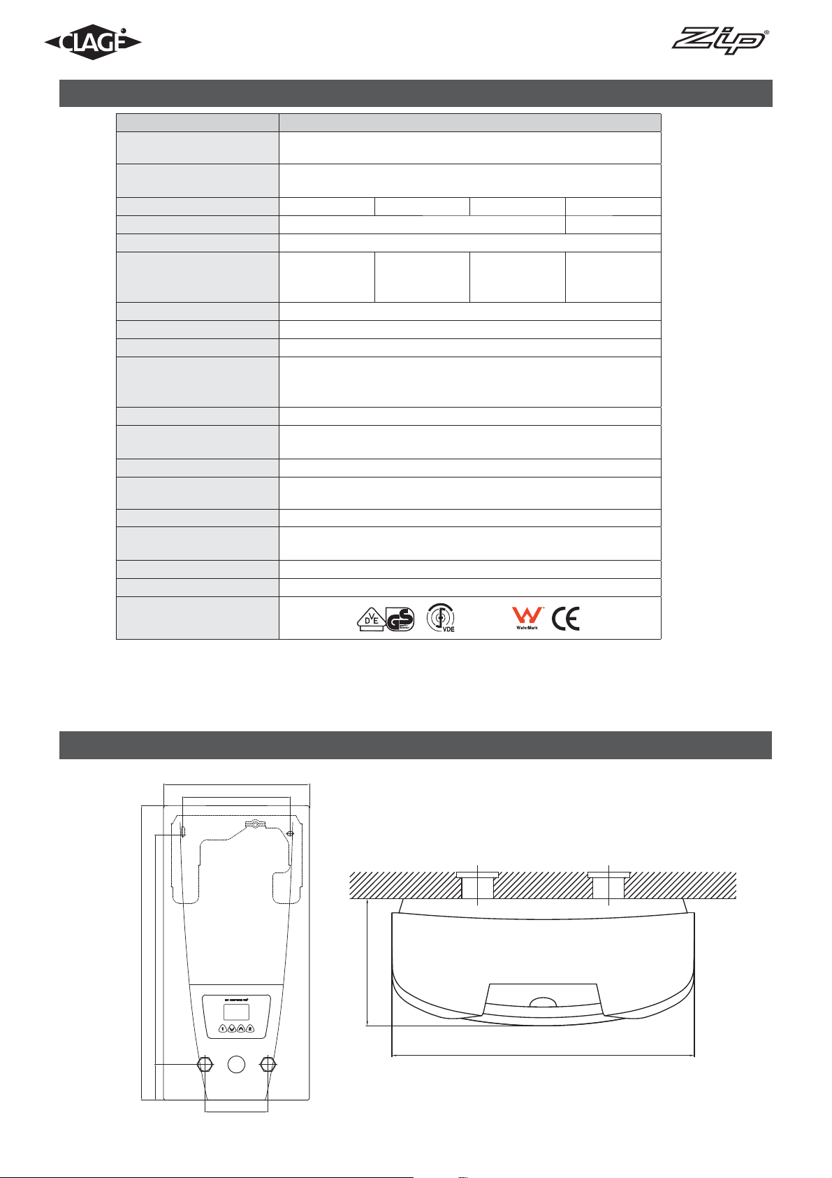
5. Dimensions
231
170
363
466
Dimensions in mm
97
56
100
231
5
Instructions for installer - 9120-34314 - DEX - 801048 - May 2013 v1.01
Page 6
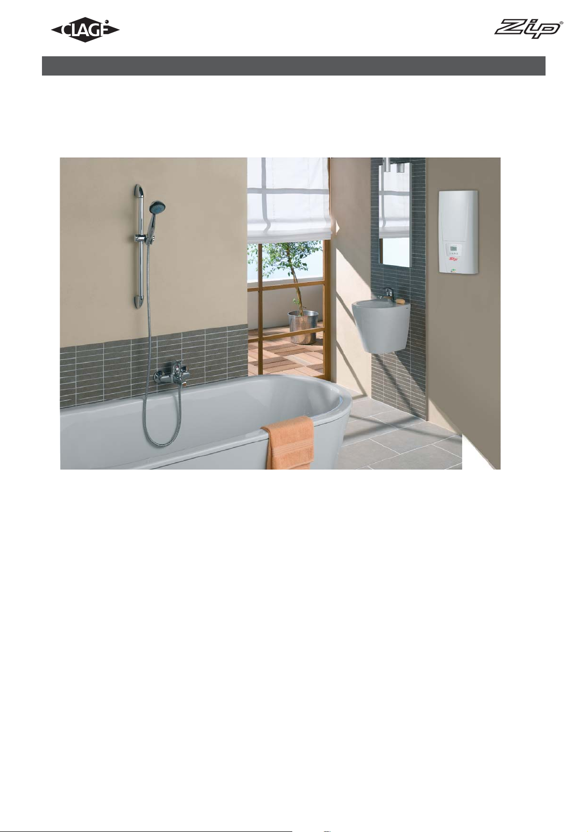
6. Typical installations
6
Instructions for installer - 9120-34314 - DEX - 801048 - May 2013 v1.01
Page 7

6. Typical installations
363 56
466
550
shut-o
upper edge of the wash basin approx. 850
valve
231
170
rear
cable
entry
100
upper edge of the shower cabin approx. 1950
alternative
rear cable entry
depth of
the unit: 97
min. 10
dimensions in mm
7
Instructions for installer - 9120-34314 - DEX - 801048 - May 2013 v1.01
Page 8

7. Installation
The following regulations must be observed:
• Installation must comply with all statutory regulations, AS/NZS 3000, AS/NZS 3500, as well as those of the local electricity and water
supply companies.
• The specifications on the rating plate.
• Technical specifications.
• These instructions must be read and fully understood before commencing the installation. If in doubt, or in need of further guidance
please ring Zip on 1800 638 633.
• Zip Instantaneous Hot Water heaters must be installed by a competent person familiar with electric instantaneous water heaters.
• Zip Instantaneous Hot Water heaters must be installed according to the specifi cation on the rating plate and the technical specifi cations.
• The appliance must be permanently connected to the electrical supply through an isolation switch as per AS/NZS 3000.
• To protect the appliance, a circuit breaker must be fi tted with a rating suitable for the nominal current of the appliance.
• The cross sectional area of the connection cable must be in accordance with the power rating of the appliance and the specifi c requirements of AS/NZS 3000.
• Take care to protect the wiring from damage during installation and ensure that the wiring is not directly accessible after installation.
• Check that the power supply is switched off prior to electrical connection.
• This appliance must be earthed.
• For 50 ºC models, the appliance delivers water not exceeding 50 ºC in accordance with AS3498.
• For 60 ºC models, the appliance may be able to be used with a Thermostatic Mixing valve or where serving a fi xture that does not
require temperature limitation such as a commercial Kitchen sink or Cleaners sink. Refer to AS/NZS 3500.4.
Installation site
• Appliance must only be installed in frost-free rooms. Never expose appliance to frost.
• The Appliance is designed for wall mounted installation and has to be installed with water connectors downwards.
• The appliance complies with protection class IP 25.
• To avoid thermal losses and dead legs, the distance between the instantaneous water heater and the furthest outlet should be kept as
short as possible (<6 meters). In addition all hot water pipe work should be insulated in accordance with AS/NZS 3500.
• For maintenance work, a shut-off valve should be installed in the supply line. The appliance must be accessible for maintenance work.
• The hot water pipes must be thermally insulated.
• The specific resistance of the water must be at least 1100 cm at 15 °C. The specific resistance can be asked for with your water
supply company.
8
Instructions for installer - 9120-34314 - DEX - 801048 - May 2013 v1.01
Page 9
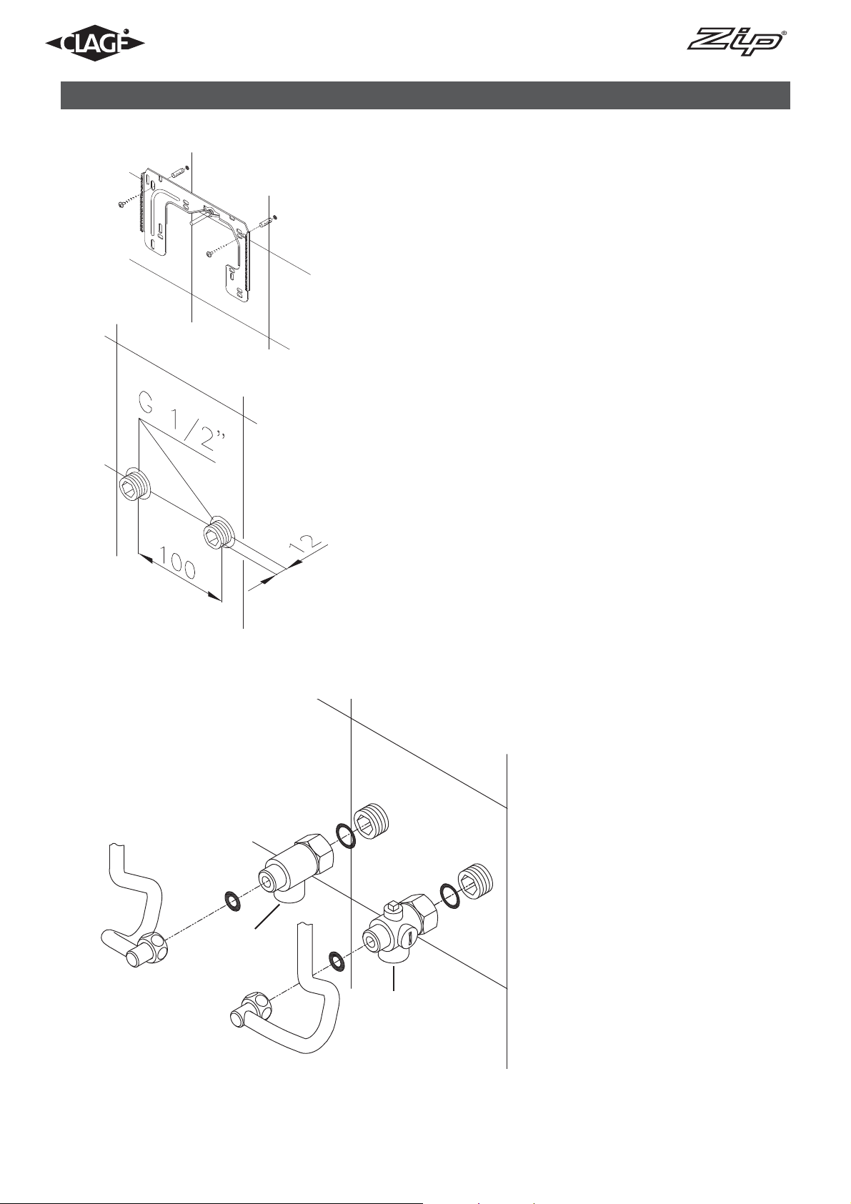
Fig 1
7. Installation
Installing the wall bracket (Fig 1)
1. Thoroughly flush the water supply pipes before installation to remove any
water borne debris.
2. If required, using a 12mm hexagon key, screw the screw in nipples into
the wall connections. After tightening the double nipples must protrude by
12mm.
3. Hold the mounting template on the wall and align it so that the holes in the
template fit over the connections. Use the template to locate the drilling
positions and drill them with a 6mm bit, ensuring that there are no hidden
cables or pipe-work. Attach the wall bracket using the fixings and screws
supplied.
4. Offset tiling or uneven surfaces can be compensated for by up to 30mm
with the aid of the spacers supplied. The spacers are fitted between the
wall and the wall bracket.
Fig 2
Installing the connection pipes (Fig 2)
1. Screw the cold water connection piece (A) with the union nut and the ½”
seal onto the cold water connection.
2. Screw the hot water connection piece (B) with the union nut and the ½”
seal onto the hot water connection..
B
A
9
Instructions for installer - 9120-34314 - DEX - 801048 - May 2013 v1.01
Page 10

7. Installation
Installing the applicance
1. Remove the appliance cover by first removing the fascia panel
then unscrewing the fixing screw.
2. If the power supply cable is to be connected in the upper part
of the appliance follow instructions for “Electrical Connection
From Above” on page 13.
3. Place the appliance on the wall bracket with the threaded
stud through the fixing hole in the back plate. If necessary the
threaded stud can be carefully bent through a maximum of
approximately 30° to allow it to align with the fixing hole (see
Fig 4). However, it must be ensured that the water connection
pipes can be connected to the appliance without applying
force.
4. Screw the two 1/2” union nuts on the appliance’s water connection pipes, each fitted with a 1/2” seal, onto the fittings.
5. Screw the plastic knurled retaining nut onto the threaded stud
of the wall bracket.
6. Open the water supply to the appliance and slowly open the
shut-off valve (see Fig 5) in the cold water connection piece to
position 1. Check all connections for leaks.
7. Ensure that all air is eliminated from the water heater by opening and closing the hot water tap until no more air emerges.
Fig 3 (3-phase model shown)
Fig 5
Fig 4
10
Instructions for installer - 9120-34314 - DEX - 801048 - May 2013 v1.01
Page 11

7. Installation
Surface mounted installation
1. If required for surface mounting, the two ½”screw-in nipples
and the ½” seals must be screwed into the ½” union nuts of
the hot water and cold water connectors. The two ½” caps
of the side outlets of the hot water and cold water connectors must be removed and screwed into the open end of the
screw-in nipples. The hot water and cold water connectors
must then be screwed into the 1/2” union nut of the appliance and delivery pipe, together with the 1/2” seals.
2. When surface mounting, it is advisable to install the appliance at a distance from the wall as illustrated in Fig 6 using
the spacer sleeves supplied. In this case the two fi xing holes
near the lower pipe connections should also be used.
3. The fl ared end of the pipes must be screwed into the ½”
side outlets of the hot water and cold water connectors
with ½” union nuts and ½” seals. The holes required for the
pipes must then be broken out of the housing using a blunt
implement.
4. Ensure the line strainer is inserted into the cold water
connection.
Electrical connection
Prior to commencing electrical connection take time to re-read the
‘Installation Requirements’ listed on page 8 and ensure that all requirements pertaining to electrical installation are observed.
3
2
3-phase
Wiring Diagram
1. Circuit board
2. Heating element
3. Safety thermal cut-out
4. Terminal block
1
4
Fig 6
11
Instructions for installer - 9120-34314 - DEX - 801048 - May 2013 v1.01
Page 12

7. Installation
Electrical connection from below
Check that the power supply is switched off prior to electrical
connection!
1. Remove inner and outer insulation from the connecting cable to the
lengths shown in Fig 7.
2. With the smaller opening foremost, slide the water splash protection
sleeve over the connecting cable until the sleeve is fl ush with the
wall. This prevents any water leaks from coming into contact with
the electrical leads. The protection sleeve must be used and free
from damage.
3. Open the control panel to the right.
4. Fit the connecting cables into the terminal block according to the
wiring diagrams on page 11. Ensure all connections are fully tightened and secure.
5. The appliance must be earthed.
6. Pull the protection sleeve over the connecting cables until it fi ts in
the recess of the intermediate panel.
7. Close the control panel.
8. Re-fi t the appliance cover and secure with the fi xing screw before
re-fi tting the fascia panel.
Note: If required, the terminal block can be re-positioned in the upper
part of the appliance. In this case the instructions in the following
section should be followed.
Fig 8
(3-phase model shown)
Fig 7
180mm
60mm
8mm
12
Instructions for installer - 9120-34314 - DEX - 801048 - May 2013 v1.01
Page 13

7. Installation
Electrical connection from above
Check that the power supply is switched off prior to electrical connection!
1. Open the prepared breaking point (S) in the upper part of the appliance by pressing with a blunt instrument (e.g. Screwdriver). See Fig 9.
2. Open the cable grommet to slightly smaller than the cable size to ensure optimum protection against
water ingress. Fit the grommet into the cable opening. N.B. The cable grommet must be used.
3. Strip the cable 6cm above the point where it emerges from the wall. Support the appliance while the
cable is routed through the grommet.
4. Unscrew the terminal block fi xing screw. Reposition the terminal block on the upper mounting and
secure with the fi xing screw.
5. Fit the connecting cables into the terminal block according to the wiring diagram on page 11. Ensure all
connections are fully tightened and secure.
6. The appliance must be earthed.
7. Re-fi t the appliance cover and secure with the fi xing screw before re-fi tting the fascia panel.
Fig 9
(3-phase model shown)
S
13
Instructions for installer - 9120-34314 - DEX - 801048 - May 2013 v1.01
Page 14

8. Commissioning
Before switching on the power supply, ensure the appliance is completely fi lled
with water by carefully opening and closing the hot water tap until all air has
been eliminated from the water heater and no more air emerges.
Every time the appliance is drained (e.g. after work on the plumbing system or
following repairs to the appliance), the heater must be re-vented in this way
before reconnecting the power supply.
The maximum power rating of the appliance can be selected from 18, 21, 24
or 27kW at the time of installation. The maximum power rating should only be
selected with reference to the technical data on page 5, after ensuring that
correct cable sizing and fuse protection is in place and with regard to local site
conditions and AS/NZS 3000 electrical regulations.
This must only be done by a qualifi ed tradesperson.
1. Switch on the power supply to the appliance. The digital display will light
up.
2. When switching on power for the fi rst time “21” will fl ash on the display. If
not, please refer to the section below “Reinstallation”.
3. Use the arrow up and down function keys ( , ) to select the required
maximum power rating. N.B. DEX at 27kW for connection only to 3/PE 400V
AC supply.
4. Press function key 1 to confi rm the selection after which the appliance will
start to operate.
5. Mark the set power rating on the product rating plate.
6. After selecting the maximum power rating, the heating element will acti-
vate after approximately 30 seconds of water fl ow.
7. Open the hot water tap and check the appliance is functioning correctly.
8. Explain operation of the appliance to the end user and leave the operating
instructions for their reference.
9. Complete the product registration card and return it to Zip Heaters or regis-
ter the product on line.
14
Instructions for installer - 9120-34314 - DEX - 801048 - May 2013 v1.01
Page 15

9. Reinstallation
If the appliance is to be re-commissioned under different installation conditions it may be necessary to alter the maximum power
rating.
This must only be done by a qualifi ed tradesperson.
To re-set the maximum power rating use a srewdriver to short circuit the two pins as shown in Fig 10. Value ‘21’ will fl ash in the
display panel until the maximum power rating has been selected.
Fig 10
15
Instructions for installer - 9120-34314 - DEX - 801048 - May 2013 v1.01
Page 16

10. Maintenance
N.B. Maintenance work must only be carried out by a qualifi ed tradesperson familiar with instantaneous water heaters.
Plastic surfaces and sanitary fi ttings should only be wiped with a damp cloth.
Never use abrasive or chloric cleaning agents or solvents.
Outlet fi ttings (tap nozzles and shower heads) should be unscrewed and cleaned at regular intervals.
The electrical and plumbing components should be inspected regularly by a competent person to ensure proper functioning
and operational safety. Water quality should be considered when determining the frequency of inspection.
Cleaning and replacing the fi lter strainer
The cold water connection of the appliance is fi tted with an integral
shut-off valve and fi lter strainer. Soiling of the strainer may reduce
hot water output from the unit.
The strainer should be cleaned or replaced as follows:
1. Isolate the electrical supply to the unit.
2. Remove the appliance cover and close the shut-off valve (see
Fig 12) in the cold water connection piece to position II.
3. Unscrew the screw plug (A) from the cold water connection
piece and take out the strainer (B) (see Fig 13).
4. The strainer can now be cleaned or replaced.
5. After re-fi tting the strainer tighten the screw plug.
6. Slowly open the shut-off valve in the cold water connection
piece to position 1.
7. Vent the unit by carefully opening and closing the hot water tap
several times until all air has been eliminated from the water
heater and no more air emerges.
8. Re-fi t the appliance cover and restore power to the unit.
Fig 12
16
A
Fig 13
B
Instructions for installer - 9120-34314 - DEX - 801048 - May 2013 v1.01
Page 17

Service-Menü ansehen Service menu
1
+
Press
2 sec
4
11. Service menu
The service menu offers an overview of system parameters and is used for
diagnostics.
Press key
2
service menu, the display confirms by “FL” and by a flashing point. Using the
arrow keys
Press key
shes in the display. (The values of some menus can be switched over by using
the arrow keys
3
pressing key
(nominal value). After two minutes without any key stroke the system automatically switches back to the standard display.
and key simultaneously for at least 2 seconds to call up the
and , you can switch between the individual menus.
to see the value of the currently selected menu. The value fla-
and .) You will get back to the drop-down-menu when
again. With key you will get back to the standard display
5
Display flashes
9
Menu item order of “Service menu“:
6
8
Flow
Power
Temp in
Individual menu items as follows:
“FL“: Flow
Indication of current flow rate given
in l/min.
7
“Po“: Power
Indication of current power consumption (kW).
“t1“: Temp in
Indication of inlet temperature (°C).
“t2“: Temp out
Indication of outlet temperature (°C).
“CA“: Control value
Indication of calibration value of the
control system. Regular range: 40 – 60.
“PL“: Power limit
Informs about the current maximum power rating (kW) of the appliance.
Temp out
Control value
Power limit
Diagnostics
Lock level
Software version
Radio channel
Received strength
Signal
“Er“: Diagnostics
Indication of the last ten diagnostic
messages.
The error code is indicated by the first displayed value after pressing key
(refer to “Abstract for Trouble-Shooting & Diagnostics” in the hood). By using
the arrow keys
and the last 10 error codes are displayed chronologically. Thereby the display indicates in turns the error numbers from “0” to “9“
and the corresponding error. The last error will be recorded at position “0” and
the former ones each shifted 1 position backwards.
“LL“: Lock level
The operating mode of the appliance can be restricted.
Setting Options:
“0” no restriction (factory setting)
“1” factory reset via key (countdown) not possible, parameters can be
seen, but not be modified in setup menu
“2” same as “1”, additionally the setup menu cannot be opened
17
Instructions for installer - 9120-34314 - DEX - 801048 - May 2013 v1.01
Page 18

11. Service menu
Menu item order of “Service menu“:
Flow
Power
Temp in
Temp out
Control value
Power limit
Diagnostics
Lock level
Software version
Radio channel
“3” same as “2” additionally nominal value memory 1 and 2 not changeable
“4” same as “3”, additionally nominal value not changeable
Note: When the setting “1“, “2“, “3“ or “4“ was chosen, the system parameters can no longer
be modified in the service menu.
In order to modify these system parameters, it is necessary to remove the jumper on the
power electronics, as specified in the chapter “Deactivation of the lock level”. (Page 13)
“nr“: Software version
Information about installed software version.
“Ch“: Radio channel
Information about the current radio channel of the water heater and its remote control.
“rS“: Received strength
Information about the current signal quality of the remote control as percentage. Depending
on the distance between remote control and water heater the value varies between 10 % and
100 %.
“IIC“: Signal
Information about the quality of the radio contact when a diagnostic display is connected.
Received strength
Signal
18
Instructions for installer - 9120-34314 - DEX - 801048 - May 2013 v1.01
Page 19

Notes
19
Instructions for installer - 9120-34314 - DEX - 801048 - May 2013 v1.01
Page 20

Head Office
Zip Heaters (Aust) Pty. Ltd.
ABN: 46 000 578 727
67 Allingham Street
Condell Park NSW 2200
Postal: Locked Bag 80
Bankstown 1885 Australia
Website: www.zipheaters.com
Facsimile: (02) 9796 3858
Programme button 1 Programme button 2
Telephone: (02) 9796 3100
Free Call: 1 800 638 633
As Zip policy is one of continuous
product improvement, changes
to specifications may be made
without prior notice. Images in this
booklet have been modified and
may not be true representations of
the finished goods.
Quick reference guide
Set temperature
1
–1 °C
Select preset temperature
A1 A2
B1 B2
Store temperature
1
Set required
temperature
(e.g. 43 °C)
+1 °C
2
Press
≥ 3 secs
1
Press + hold!
Arrow keys up and down
Reset
2
+
3
Power limit
Unit provides no output
Reset completed
4 3
Display of new value (e.g. 43 °C)
Instructions for installer - 9120-34314 - DEX - 801048 - May 2013 v1.01
 Loading...