

Zip AquaFlo II AF3210, AquaFlo II AF3120, AquaFlo II AF3150, AquaFlo II AF3180, AquaFlo II AF3250 Installation, Maintenance And User Instructions
...
AquaFlo II
Unvented Water Heaters
Issued October 2012
Installation, Maintenance and User Instructions
Please read these instructions carefully before commencing installation.
Please leave these instructions with the end user after installation.
Zip Heaters (UK) Ltd.
14 Bertie Ward Way
Dereham
Norfolk
NR19 1TE
Telephone: 0845 6024533
Fax: 01362 692448
Web: www.zipindustries.co.uk
The terms ‘Zip’ and ‘InLine’
are registered trademarks
Front cover A5_BookletBack cover

Inside Back cover Inside Front cover
AquaFlo Installation, Maintenance and User Instructions Page 1 of 24 V 2.01 - October / 2012
Contents 1
Description 2
Approvals 2
Safety Information 3
Technical data 4 / 12
Parts List 13
Installation 14
Requirements 14
Installation Site 15
Installing the appliance 15
Electrical connection / circuit diagram 20 / 21
Commissioning 22
Annual servicing 23
Warranty 24
Please read these instructions carefully before commencing installation of the AquaFlo
unvented Water Heater.
Please leave these instructions with the end user after installation.
To ensure you have the latest revision of this instruction manual, please visit
www.zipindustries.co.uk to download the latest copy.
In order to preserve our environment we ask that you dispose of this product correctly.
Please contact Zip Customer Service for advice on 0845 602 4533.
AquaFlo Installation, Maintenance and User Instructions Page 2 of 24 V 2.01 - October / 2012
Equipment Supplied with Cylinder Direct Indirect
Solar Twin
Coil
Solar
Direct
Dual Control Thermostat (Indirect Models Only)
û
û
Thermostat (High Limit)
û û
Two Port Zone Valve (Indirect Models Only)
û
û
Cold Water Inlet Set
15 x 22 mm Tundish
Temperature & Pressure Relief Valve
Expansion Vessel
Expansion Vessel Bracket
¾” BSP Female X 22 mm Connection for Expansion Tank
Immersion Heater(s) - Dependant on size and conguration
Grommet for Solar Sensor
û û
Instruction Manual
DESCRIPTION
The corrosion resistant Zip AquaFlo Unvented cylinder is made from Duplex Stainless Steel. It is
highly insulated with environmentally friendly foam enclosed in a rust resistant white steel case.
It is available in Direct and Indirect versions in a family of 7 sizes from 90 – 300 litres. Triple
element options are available on Direct 210 – 300 litre units. Twin Coil and Solar Direct units are
available in 5 sizes from 150 - 300 litres.
To help ensure compliance with the relevant Water and Building Regulations all AquaFlo units
are supplied complete with the necessary safety and control devices needed to connect to the
cold water mains. In order to ensure high ow-rate performance with minimum pressure drop even
in lower pressure areas, pre-adjusted, high quality controls have been selected.
APPROVALS
KIWA approved to UK Water Regulations and UK Building Regulations Part G3 and Part L.
Immersion element / thermostat BEAB / NEMKO approved and CE endorsed.
Storage prior to installation
Zip AquaFlo should be stored upright in a dry area and kept in its original packaging until
immediately prior to installation.
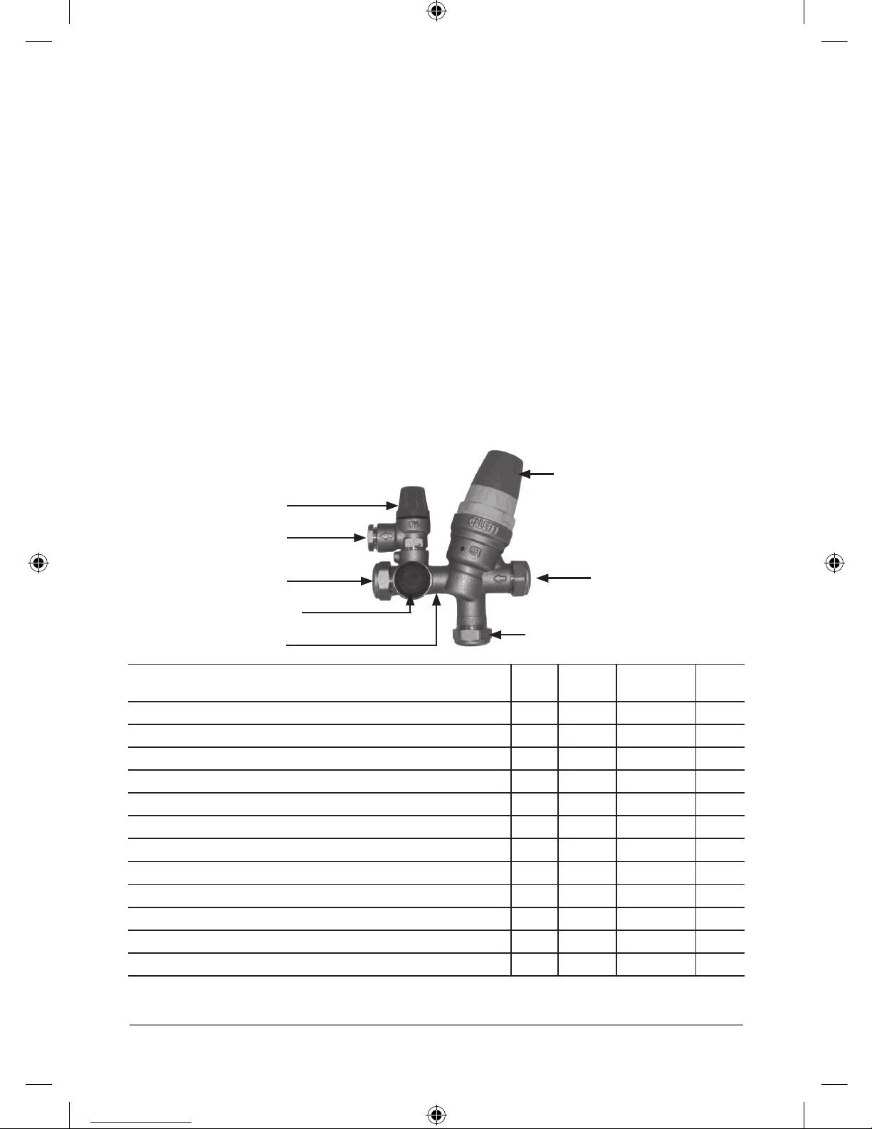
Cold Inlet Set - Connections
Cold Mains In
Balanced Cold Take Off
Cold Supply To Cylinder
Internal Check Valve
Expansion Vessel Take Off
Discharge To Tundish
Expansion Relief Valve
Pressure Reducing Valve (inc.
Line Strainer)
Additional items required (not supplied): Drain for the cold inlet. Isolating valve for the cold feed
supply.
AquaFlo Installation, Maintenance and User Instructions Page 3 of 24 V 2.01 - October / 2012
SAFETY INFORMATION
WARNING
• Installation, commissioning and maintenance of this appliance must only be carried
outbyacompetentinstallerholdingtheirG3unventedqualication, who will then be
responsible for adhering to all relevant standards and regulations.
• The appliance must be wired to a suitably rated double pole fused spur.
• Electrical installation must comply with IEE regulations.
• Isolate appliance at the main electric supply before opening the heating element cover.
• The connection cable must be 2.5mm2 heat resistant (85°C HOFR) sheathed ex complying
to BS 6141:1981.
• This appliance must be earthed at all times.
• The connecting cable must be adequately secured.
• Check that the power supply is switched off prior to electrical connection.
• The appliance, its wiring and piping must not be modied in any way.
• The appliance must only be used when correctly installed and in perfect working order.
• Maximum water supply pressure
1.0 MPa (10 bar)
.
• Explosion hazard. Safety ttings such as the temperature & pressure relief valve must not
be modied.
• The appliance must not be used for any purpose other than that for which it was designed.
• When the appliance has been in use for some time, the ttings may be very hot.
• This appliance must not be used by any person (inclu ding children) with limited physical,
sensorial or mental abilities or failing experience and/or knowledge unless they are
supervised by a person responsible for their safety or received instructions about how to
use the appliance. Children should be supervised in order to make sure that they do not play
with the appliance.
• Take care when lifting the Zip AquaFlo. Some units may exceed safe lifting limits. Do not
lift without assistance. The weights of the units are given in the specifications table (see
specications on page 10 to 12)
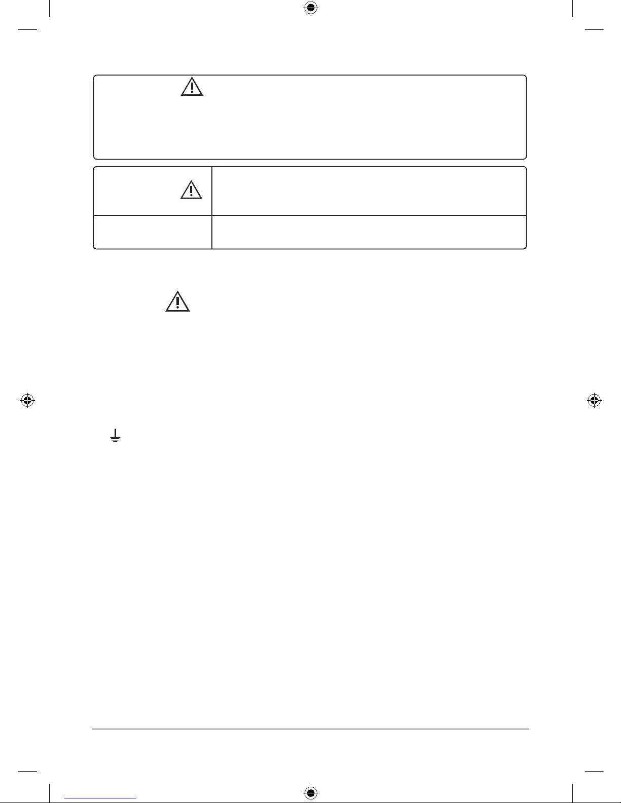
WARNING:
Indicates a potentially hazardous situation, which, if
not avoided, could result in death and/or serious injury
and/or property damage.
CAUTION:
Indicates a potentially hazardous situation, which, if not avoided,
may result in property damage.
IMPORTANT:
PLEASE READ THESE INSTRUCTIONS CAREFULLY.
NOTE THE SAFE OPERATIONAL REQUIREMENTS, WARNINGS AND CAUTIONS. USE THIS PRODUCT CORRECTLY
AND WITH CARE FOR THE PURPOSE FOR WHICH IT IS INTENDED. FAILURE TO DO SO MAY CAUSE DAMAGE
AND/OR PERSONAL INJURY, AND WILL INVALIDATE THE WARRANTY. RETAIN THESE INSTRUCTIONS FOR FUTURE
USE.

AquaFlo Installation, Maintenance and User Instructions Page 4 of 24 V 2.01 - October / 2012
CAUTION!
• In case of malfunction isolate the power supply immediately. In case of leaks also isolate the
water supply. Repairs must only be carried out by Zip Heaters (UK) Ltd or an authorised Zip
service engineer.
• If siting outside the heating envelope of the dwelling such as a garage or outbuilding then
frost protection should be provided and exposed pipework should be insulated.
• The appliance must be completely lled with water before being switched on.
• The appliance must only be used for heating wholesome water.
• Minimum water supply 0.15 MPa (1.5 bar), 20 l/min.
• The Zip AquaFlo is intended for connection to mains supply only. In any other case please
contact Zip on 0845 602 4533 for advice.
Zip Heaters (UK) Ltd. cannot be held liable for any damages caused by failure to observe
these instructions.
TECHNICAL DATA / SPECIFICATION
Maximum water supply pressure to pressure reducing valve ...................1.0 MPa (10 bar)
Note!
If supply is above 1.0 MPa (10 bar) a pressure control valve must be used to bring
the pressure under 1.0 MPa (10 bar) before connection to the pressure reducing valve.
Operating pressure .................................................................................... 0.3 MPa (3 bar)
Maximum primary pressure (indirects only) ...............................................0.3 MPa (3 bar)
Immersion Elements: Incology construction 1¾” thread, 14” long, loading 3kW @ 240V.
Note! Titanium elements are also available for areas where aggressive water, constant cycling
and high usage are factors. (See parts on page 13).
Heat Exchanger: 22mm low prole, high efciency stainless steel coil-in-coil.
Controls:
• Thermostat adjustable up to 65°C.
• Over temperature safety cut-out. Manually re-settable. Operates at 85°C.
• Expansion relief valve -
0.6 MPa (6 bar)
.
• Temperature and pressure relief valve - 90°C and 0.7 MPa (7 bar).
• Pressure reducing valve - 0.3 MPa (3 bar).
• Expansion vessel - pre-charged
0.3 MPa (3 bar)
.
• 90 - 150 Ltr units: 12 Ltr vessel.
• 180 - 250 Ltr units: 18 Ltr vessel.
• 300 Ltr units: 24 Ltr vessel.
AquaFlo Installation, Maintenance and User Instructions Page 5 of 24 V 2.01 - October / 2012
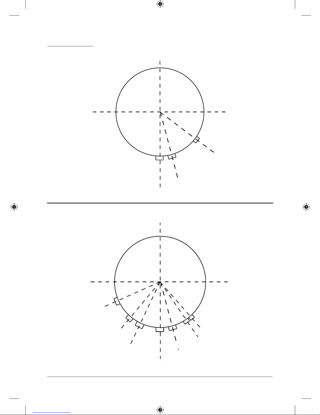
Connection Points
AquaFlo Indirect and Solar Compatible
Immersion
Cold Inlet
Primary Coil
T&P Valve
Stat Pocket
Sec Return
Primary Coil
38°
35°
25°
40°
66°
15°
Immersion
T&P Valve
Cold Inlet
AquaFlo Direct
45°
15°
AquaFlo Installation, Maintenance and User Instructions Page 6 of 24 V 2.01 - October / 2012
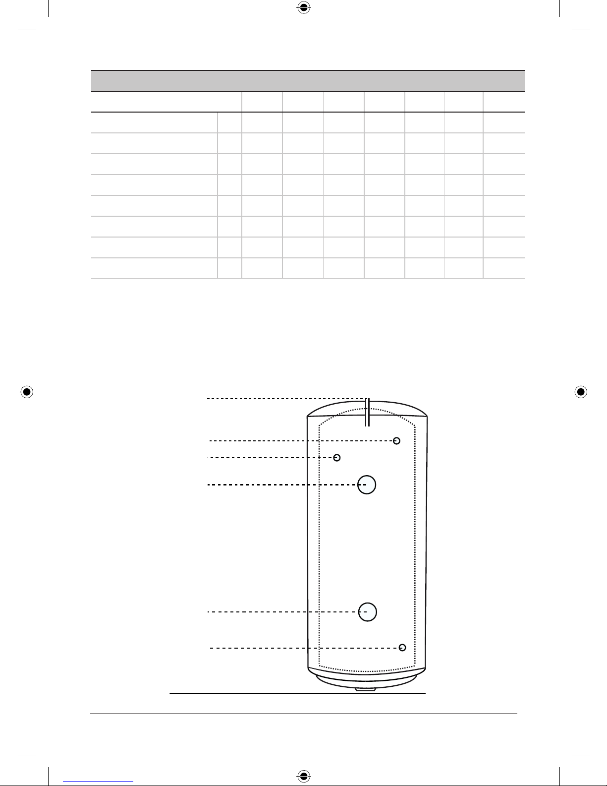
AQUAFLO DIRECT DIMENSIONS
Model AF3090 AF3120 AF3150 AF3180 AF3210 AF3250 AF3300
Nominal Capacity (Litres) 90 120 150 180 210 250 300
Diameter (mm) 545 545 545 545 545 545 545
Height (mm) A 727 915 1102 1290 1478 1728 2041
T & P Valve (mm) B 515 703 890 1078 1266 1516 1829
Sec. Return (mm) C - - - - 1009 1259 1509
Immersion 2 (mm) D - 519 619 719 819 959 1109
Immersion 1 (mm) E 242 242 242 242 242 242 242
Cold Inlet (mm) F 192 192 192 192 192 192 192
A
B
C
D
E
F
 Loading...