

Page 1
Zip Filter Mixer Tap
Installation Instructions
Affix Model Number Label Here
805280
Zip Filter Mixer Tap - Installation & Operating Instructions - 805280 - August 2017 v1.00 Page 1 of 8
Page 2
Read these Warnings First
Please read all installation requirements, installation procedures and precautions before installing any Zip
Filter Mixer Tap.
Never attempt to install any Zip Filter Mixer Tap without reading all of the applicable instructions.
These products ares not intended for use by persons (Including Children) with reduced physical, sensory
or mental capabilities, or lack of experience and knowledge, unless they have been given supervision or
instruction concerning use of the appliances by a person responsible for their safety.
Children should be supervised to ensure they do not play with the product.
The product is for indoor use only and must not be exposed to the elements of nature.
All plumbing connections must be made in accordance with AS/NZS3500.
Before installing, ensure there is cold water supply with a minimum working pressure of 70 kPa and a
maximum working pressure of 700 kPa. (A 350 kPa limiting pressure valve is supplied)
Cold water supplied must not exceed 38°C.
Hot water supplied to the mixer must not exceed 70°C.
Installation Instructions
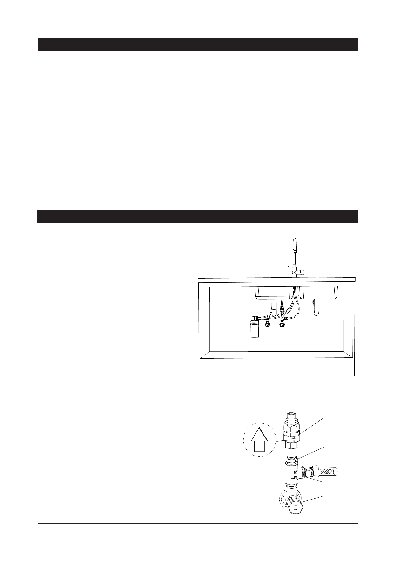
Install the Filter
The filter (A) should be mounted as close as
possible to the front of the cupboard, to allow for
ready and easy access during filter changes.
1. Usually the side of the cupboard, near the
door, is most suitable.
2. Using the two screws provided, screw the
filter head to the inside of the cupboard, allowing
260mm minimum between the underside of the
filtration head and any obstructions like shelves,
etc.
Fig.1
A
3. Write the installation date on the filter
cartridge. Fit the cartridge into the housing. The
model you have may appear slightly different to
that illustrated, however, operation and function
is identical.
4. Align the tabs of the cartridge with the filter housing and insert it into the socket. Turn the cartridge a
quarter turn to the right until it stops and locks into position, see Filter Replacement section on page 5.
5. Check that the direction of flow on the filter head is correct.
PLV Valve
Install the 350 kPa Pressure Limiting (PLV) /
Double Non-Return valve
1/2” Nipple
Flow Direction
Fit the PLV valve to a 1/2” nipple which connected to a 1/2” tee
piece as shown in Fig.2 connect to the cold water supply. (Teflon
plumbing tape required).
1/2” Tee piece
NOTE: the directional arrow is shown on the body of the valve.
Fig.2
Page 2 of 8 Zip Filter Mixer Tap - Installation & Operating Instructions - 805280 - August 2017 v1.00
Isolation valve
Page 3
Installation Instructions
Install the Filter Mixer Tap
1. Position the Filter Mixer Tap at the back of the sink where there
is a mimium 45 mm wide flat area. Make sure the selected position
allows the spout to overhang the sink bowl.
The cutout size is 35 mm. Mark the centre of the new filter mixer tap
position on the sink with a centre punch.
Fig.3
2. Drill out the centre of the hole to allow the screw of a sheet metal
punch to pass through the sink. Use a 35 mm sheet metal hole
punch to neatly open up the hole.
3. Remove the nut and washer from the base of the Filter Mixer Tap,
and pass the hoses through the sink until the Filter Mixer Tap sits
upright within the hole you just created in the sink surround. When
fitting to a thin work surface use the white plastic stabilising clamp
supplied, to improve the support of the tap.
4. Orientate the Filter Mixer Tap so that the activating levers are
parallel to the wall of the kitchen. Slide on the washer and nut from
beneath the sink, and tighten the nut to secure the Filter Mixer Tap
firmly into place.
5. One blue braided and one red braided hose hangs from the bottom
of the Filter Mixer Tap. The blue braided hose connects to the tee
piece, which is connected to the mains isolation valve for cold water,
see Fig.3. The red braided hose connects to the mains isolation valve for
hot water.
Stem ended
Braided Hose
Mains isolation
valve for hot
water
Red
Braided
Hose
Blue
Braided
Hose
Mains isolation
valve for cold
water
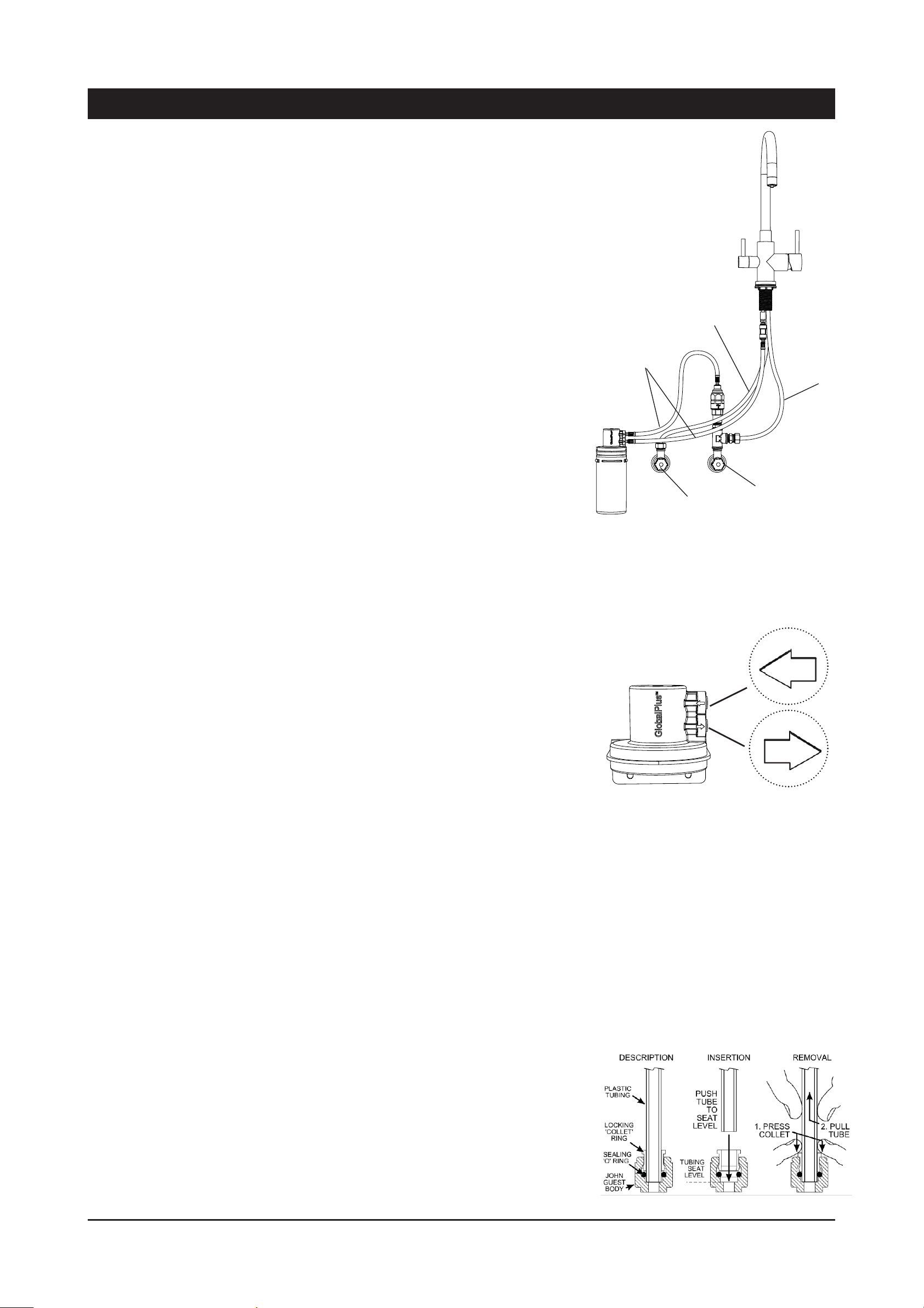
6. Screw the brass connector with JG fitting into the remaning outlet
on the bottom of the mixer tap.
7. Connect one of the stem ended braided hose from the PLV valve to
the inlet of the filter head, see Fig.4.
8. Connect the other stem ended braided hose from the outlet of the
filter head to the straight JG connector at the bottom of the Filter Mixer
Tap (see Fig.3 & Fig.4).
Take care, when bending braided hoses, to prevent it from kinking
or crushing on a bend. Please be careful to ensure the colour and
connection of the braided hoses on the Filter Mixer Tap are correct.
Do not connect the hoses in any other arrangement than that described
here. The filter cartridge and the Filter Mixer Tap have directional
flow connections that will not work if connected incorrectly. Incorrect
installation will void any product warranty.
NOTE: the flow direction of the filter housing is indicated on the filter
housing, see Fig.4.
Fig.4
Inlet
Outlet
Note: the direction arrows on the
fi lter head instructions on how to
connect JG tubing and fi ttings.
John Guest fittings
Insertion and removal details for JG fittings using plastic tubing.
1. Cut the tube squarely with a sharp knife or tube cutter. Shake out
and remove any swarf or debris.
2. Push this end of the blue tube firmly into the John Guest socket on the
(lower) outlet side of the filter head. It must push in at least 10 mm.
3. Test the connection by trying to pull the tube out. If it comes out,
re-insert it so that it won’t come out when pulled against.
4. To remove the tube, press the collet into the fitting and at the same
time pull back on the tube.
Zip Filter Mixer Tap - Installation & Operating Instructions - 805280 - August 2017 v1.00 Page 3 of 8
Fig.5
Page 4

Installation Instructions
Fill the system
1. Turn on the water supply. Check the connections for leaks. Repair
any found.
The filter and tubing are full of air until purged, and the filter cartridge
requires flushing when first installed.
2. Open the Filter Water lever on the Filter Mixer Tap for a minimum of
five minutes, until all of the air has been purged from the system, and
the filter cartridge has time to become fully flushed (10L).
Every time the filter cartridge is replaced, repeat this procedure of a
five minute flush to flush the new cartridge properly.
NOTE: When flushing the system, some black particles may be
released into the water. This is normal. The water will become clear
after the first few litres.
Filter Water
Lever
Mixer Lever
Open and flush the cold and hot water supply of the mixer tap.
Complete the installation
Leave these instructions with client.
Troubleshooting
Problem Cause Remedy
No water at outlets Water not connected Connect and turn on
Poor flow at outlet Blocked filter Replace filter
Fig.6
water
Service
Service
All service work must only be carried out by a suitably qualified and experienced service person.
Before calling for service, check the water supply is turned ‘ON’ and OK.
Call Zip in Australia on 1800-638-633 for assistance, service, spare parts, or enquiries.
Cleaning
Never use strong, corrosive or abrasive cleaning materials on the Zip Filter Mixer
Tap. Wipe the outer surfaces clean with a sponge or a soft cloth using a mild soap
and water.
Page 4 of 8 Zip Filter Mixer Tap - Installation & Operating Instructions - 805280 - August 2017 v1.00
Page 5

Filter Replacement
Not changing cartridges when required may cause the water to become
biologically unsafe.
Thoroughly flush the water through, if the Filter Mixer Tap has not been
used for more than 12 hours. For safe operation, the filter cartridge
should be replaced at least every 6-12 months, or earlier if you notice a
persistent reduction in water pressure from the tap, or an unpleasant
taste or odour in the water. Use only a Zip filter cartridge to match that
of your Filter Mixer Tap. Replacement cartridges can be obtained through
plumbing suppliers or directly from Zip.
Replacing a Zip Filtration cartridge is as easy as 1-2-3.
1. Unplug the old cartridge
2. Plug in the new cartridge.
3. Purge the filter system by flipping the Filter Mixer Tap lever open (on)
for a few minutes until the water runs clear (10l).
FILTER CARTRIDGE
REPLACEMENT
REMOVE FILTER
1. ROTATE
2. PULL DOWN
Fig.7
INSERT FILTER
High sediment water areas.
Zip Filter Mixer Tap 94574 is a single filter system suitable for areas
in which water supply sediment is not a problem. In areas with heavy
sediment contamination, you may wish to replace your 0.2 micron filter
with a 3 micron filter, at first filter change. Refer to page 7 for cartridge
kit numbers.
Operating Procedures
Operating
1. INSERT
2. ROTATE
Fig.8
You can obtain filtered water (within the rated capacity for) as
long as you rotate the lever.
In the upright position the tap is off.
For filtered water, rotate filtered water lever 90° forward as
shown in Fig.9.
For mixed water, first open the Mixer by swinging the lever 25°
away from the cenre, then rotate 45° forward or reverse from
vertical axis.
Water will continue to flow until the lever is returned to the
upright position.
2. rotate 45°
forward or
reverse
1. swing
the lever
25° away
from the
cetre
Fig.9
Zip Filter Mixer Tap - Installation & Operating Instructions - 805280 - August 2017 v1.00 Page 5 of 8
Page 6

Filter Performance Data - 0.2 Micron
WM -0350001
Global-Mark.com.au
HEALTH CLAIM PERFORMANCE CERTIFIED BY NSF
This system has been tested according to NSF/ANSI Standards 42 and 53 for the reduction of the substances
listed below. The concentration of the indicated substances in water entering the system was reduced to a
concentration less than or equal to the permissible limit for water leaving the system, as specifi ed in NSF/
ANSI Standard 42 and 53.
Substance
Influent
Challenge
Concentration
Average
Influent
Concentration
Maximum
Acceptable
Value‡
STANDARD 42 AESTHETIC EFFECTS
Chlorine 2.0 mg/L ± 10% 2 mg/L
Particulate Class I
particles 0.5 to <5μm
at least 10,000
particles / mL
6,433,333/L ≥ 85% 47,388/L 99.3%
Bacteriostatic Unit passes NSF Std. 42 for Bacteriostatic effects.
4 mg/L /
5 mg/L
STANDARD 53 HEALTH EFFECTS
Cyst Minimum 50,000 / L
Lead 8.5 0.15 mg/L ± 10% 0.155 mg/L
Lead 6.5 0.15 mg/L ± 10% 0.147 mg/L
99.9% /
<1/100 L
0.015 mg/L /
0.01 mg/L
0.015 mg/L /
0.01 mg/L
Maximum
Permissible Water
Concentration
Reduction
Requirements
Average
Effluent
Concentration
≥ 50% 0.05 mg/L 97.4%
99.95% 99.99%
0.010 mg/L 0.001 mg/L 98.9%
0.010 mg/L 0.0005 mg/L 99.3%
Average
Reduction
*Tested using flow rate = 1.0 gpm; pressure = 60 psig ± 3; pH = 7.5 ± 0.5; temp. = 20° ± 3°C
‡ United States Environmental Protection Agency (USEPA) Safe Drinking Water Act / New Zealand Ministry of Health Drinking-water Standards for New Zealand
This appliance meets the domestic water treatment appliance Standards
AS/NZS 3497 and AS/NZS 4348 for the following water process:
System Tested and Certifi ed by NSF International
Class Treatment Type Function Pass
I Microbiological Status
Bacteriostatic Will stop bacteria increasing, but will
not remove unless II(a) is passed.
II Microbiological Treatment
II (a) Bacteria Removal Will remove or inactivate bacteria.
II (b) Virus Removal Will remove or inactivate virus.
II (c) Protozoa Removal
III Particulate Reduction Reduces cloudiness.
IV Taste and Odour Reduction Reduces tastes and odours.
V Chemical Treatment Decreases certain chemicals:
Legend: 9= Pass N/A = Not Applicable
Cryptosporidium
Will not remove or inactivate bacteria
unless II(a) and II(b) are passed.
– Lead
and
Giardia
.
9
N/A
N/A
9
9
9
9
against NSF/ANSI Standard 42 and 53 for the
reduction of:
STANDARD NO.42 - STANDARD NO.53 AESTHETIC EFFECTS HEALTH EFFECTS
Bacteriostatic Effects Chemical Reduction
Chemical Reduction Lead
Taste & Odor Mechanical Filtration
Chlorine Cyst
Mechanical Filtration
Nominal Particulate Class I
OPERATING SPECIFICATIONS
* The term “bacteriostatic” indicates that the
system limits the passage or growth of bacteria
• Pressure requirement: 10 -125 psi (0.7 - 8.6
that may already exist in the incoming water. It
bar), non-shock
does not mean that water leaving the system is
• Temperature: 35 -100°F (2-38°C)
safer to drink than water entering the system.
Model Flow
Rate
0.2mic MicroPurity
3.75 Lpm 4163 L 93701
Capacity Cartridge
Kit
Filter 1S
0.2mic MicroPurity
fi lter 1.5S
0.2mic MicroPurity
5.678 Lpm 6813 L 93702
5.678 Lpm 9463 L 93704
AS/NZS 3497
AS/NZS 3497
WM-0350001
WM -0350001
Global-Mark.com.au
Global-Mark.com.au
Filter 2S
Page 6 of 8 Zip Filter Mixer Tap - Installation & Operating Instructions - 805280 - August 2017 v1.00
Page 7

Filter Performance Data - 3 Micron
Infl
A
Maxi
Maxi
A
WM -0350001
Global-Mark.com.au
HEALTH CLAIM PERFORMANCE CERTIFIED BY NSF/ANSI *
This system has been tested according to NSF/ANSI 42 for the reduction of the substances listed below. The
concentration of the indicated substances in water entering the system was reduced to a concentration less
than or equal to the permissible limit for water leaving the system, as specifi ed in NSF/ANSI Standard 42.
Substance
uent
Challenge
Concentration
verage
Influent
Concentration
mum
Acceptable
Value‡
mum
Permissible Water
Concentration
STANDARD 42 AESTHETIC EFFECTS
Giardia
4 mg/L /
5 mg/L
9
N/A
N/A
.
N/A
N/A
9
N/A
Chlorine 2.0 mg/L ± 10% 2 mg/L
Particulate Class II
particles 1 to <5μm
Bacteriostatic Unit passes NSF Std. 42 for Bacteriostatic effects.
*Tested using flow rate = 1.0 gpm; pressure = 60 ± 3 psig; pH = 7.5 ± 0.5; temp. = 20° ± 3°C
‡ United States Environmental Protection Agency (USEPA) Safe Drinking Water Act /
New Zealand Ministry of Health Drinking-water Standards for New Zealand
This appliance meets the domestic water treatment appliance Standards
AS/NZS 3497 and AS/NZS 4348 for the following water process:
Class Treatment Type Function Pass
I Microbiological Status
Bacteriostatic Will stop bacteria increasing, but will
II Microbiological Treatment
II (a) Bacteria Removal Will remove or inactivate bacteria.
II (b) Virus Removal Will remove or inactivate virus.
II (c) Protozoa Removal
III Particulate Reduction Reduces cloudiness.
IV Taste and Odour Reduction Reduces tastes and odours.
V Chemical Treatment Decreases certain chemicals:
Legend: 9= Pass N/A = Not Applicable
at least 10,000
particles / mL
not remove unless II(a) is passed.
Cryptosporidium
Will not remove or inactivate bacteria
unless
II(a) and II(b) are passed.
– Lead
and
OPERATING SPECIFICATIONS
• Pressure requirement: 10 -125 psi (0.7 - 8.6 bar),
non-shock
• Temperature: 35 -100°F (2-38°C)
verage
Reduction
Requirements
≥ 50% 0.05 mg/L 90.6%
≥ 85% 97.1%
Effluent
Concentration
System Tested and Certifi ed by NSF Interna-
tional against NSF/ANSI Standard 42 for the
reduction of:
STANDARD NO.42 -
AESTHETIC EFFECTS
Bacteriostatic Effects
Chemical Filtration
Taste & Odor
Chlorine
Mechanical Filtration
Nominal Particulate Class II
* The term “bacteriostatic” indicates that
the system limits the passage or growth of
bacteria that may already exist in the incoming
water. It does not mean that water leaving the
system is safer to drink than water entering
the system.
Average
Reduction
Model Flow
Rate
3mic MicroPurity
3.75 Lpm 13248 L 93703
fi lter 1.5S
3mic MicroPurity
5.678
Capacity Cartridge
Kit
AS/NZS 3497
AS/NZS 3497
WM-0350001
WM -0350001
Global-Mark.com.au
Global-Mark.com.au
17034 L 93705
Filter 2S
Lpm
It is essential that the manufacture’s recommended installation, maintenance and filter replacement requirements be carried out for the product to perform as advertised. See installation Manual for details.
NOTE: While the testing was performed under standard laboratory conditions, actual performance may vary.
Zip Filter Mixer Tap - Installation & Operating Instructions - 805280 - August 2017 v1.00 Page 7 of 8
Page 8

Contact Details
Head Office
Zip Heaters (Aust) Pty. Ltd.
ABN 46 000 578 727
67-77 Allingham Street
Condell Park NSW 2200
Postal: Locked Bag 80
Bankstown 1885 Australia
Website: www.zipwater.com
Telephone (02) 9796 3100
Free Call 1 800 638 633
The term “Zip” is a registered trademark.
As Zip policy is one of continuous product improvement, changes to specifi cations
may be made without prior notice. Images in this booklet have been modifi ed and
may not be true representations of the fi nished goods.
The standard cup referred to in this publication is 167 ml (6 fl oz).
© 2017 Zip Heaters (AUST) Pty. Ltd. All Rights Reserved.
The terms “Zip”, “GlobalPlus”, “MicroPurity” are trademarks of Zip Heaters (AUST)
Pty Ltd.
Products described in this publication are manufactured under one or more patents
and further patent applications are pending.
One or more products described in this publication are also registered designs of
Zip Heaters (AUST) Pty Ltd.
Zip Filter Mixer Tap - Installation & Operating Instructions - 805280 - August 2017 v1.00 Page 8 of 8
 Loading...