

Page 1
Installation & Operating Instructions - 89914 - Zip ChillTap Sparkling - Jan 2016 v1.04 Page 1 of 20
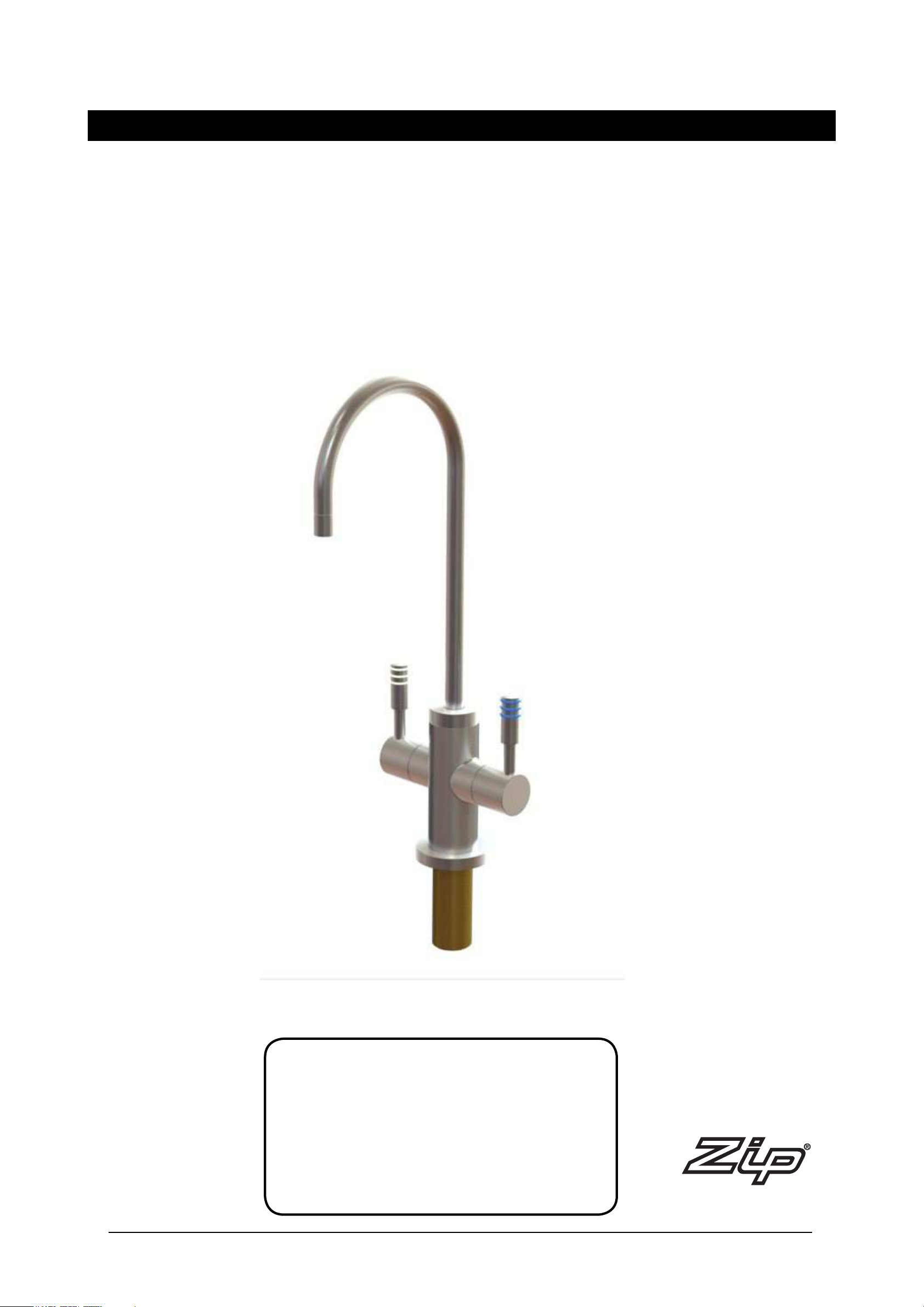
Installation and Operating Instructions
Zip ChillTap Sparkling
®
Filtered chilled still and chilled sparkling water
Affix Model Number Label Here
89914
Page 2

Installation & Operating Instructions - 89914 - Zip ChillTap Sparkling - Jan 2016 v1.04 Page 2 of 20
Notes
Page 3

Installation & Operating Instructions - 89914 - Zip ChillTap Sparkling - Jan 2016 v1.04 Page 3 of 20
Contents
Pre-Installation Notes . . . . . . . . . . . . . . . . . . . . . . . . . 4 Read
These Warnings First . . . . . . . . . . . . . . . . . . . . . . . . . . . . . . . . 4
Product Specifications. . . . . . . . . . . . . . . . . . . . . . . . . 5
Section 1 - Tap Installation. . . . . . . . . . . . . . . . . . . . . . . . . . . . 6
1.1 - Installing the Tap . . . . . . . . . . . . . . . . . . . . . . . . . . . . . . 6
Section 2 - Ventilation . . . . . . . . . . . . . . . . . . . . . . . . . . . . . . . 7
2.1 - Ventilation (all models) . . . . . . . . . . . . . . . . . . . . 7
2.2 - Extra ventilation. . . . . . . . . . . . . . . . . . . . . . . . . . 8-9
Section 3 - CO2 Cylinder . . . . . . . . . . . . . . . . . . . . . . . . . . . . . 10
3.1 - Secure the cylinder mounting . . . . . . . . . . . . . . . 10
3.2 - Connect the regulator . . . . . . . . . . . . . . . . . . . . . 10
3.3 - Connect the gas hose . . . . . . . . . . . . . . . . . . . . . 10
Section 4 - Undersink unit installation . . . . . . . . . . . . . . . . . . . 11
John Guest (J.G.) fittings . . . . . . . . . . . . . . . . . . 11
4.1 - Chiller Installation . . . . . . . . . . . . . . . . . . . . . . . . 12
4.2 - Hose and Tube connections . . . . . . . . . . . . . . . . 12
4.3 - CO2 gas Connections . . . . . . . . . . . . . . . . . . . . . 13
Soap test. . . . . . . . . . . . . . . . . . . . . . . . . . . . . . . 13
Section 5 - Commissioning . . . . . . . . . . . . . . . . . . . . . . . . . . . 14
5.1 - Test and Commission . . . . . . . . . . . . . . . . . . . . . 14
Operation. . . . . . . . . . . . . . . . . . . . . . . . . . . . . . . . . . . 14
Section 6 - Maintenance . . . . . . . . . . . . . . . . . . . . . . . . . . . . . 15-16
Water filter. . . . . . . . . . . . . . . . . . . . . . . . . . . . . . . . . . 15
Air Filter. . . . . . . . . . . . . . . . . . . . . . . . . . . . . . . . . . . . 16
CO2 Replacement. . . . . . . . . . . . . . . . . . . . . . . . . . . . 16
Trouble Shooting. . . . . . . . . . . . . . . . . . . . . . . . . . . . . 17-18
Cleaning . . . . . . . . . . . . . . . . . . . . . . . . . . . . . . . . . . . 18
End of Life Disposal . . . . . . . . . . . . . . . . . . . . . . . . . . 18
Notes. . . . . . . . . . . . . . . . . . . . . . . . . . . . . . . . . . . . . . 19
Contact Details . . . . . . . . . . . . . . . . . . . . . . . . . . . . . . 20
Page 4
Page 4 of 20 Installation & Operating Instructions - 89914 - Zip ChillTap Sparkling - Jan 2016 v1.04
Read These Warnings First
1. Please read all Precautions, Installation Requirements, Installation
Instructions before installing any Zip ChillTap.
2. Never attempt to install any Zip ChillTap without reading all of the
applicable instructions.
3. All electrical connections must comply with current wiring rules.
4. This appliance is not designed for use by young children or infirm people
without supervision.
5. Young children should be prevented from having access to ensure they
are not able to use or play with the chiller.
6. This appliance must be earthed.
7. If the power supply cord is damaged it must be replaced by a Zip
Service Provider or a qualified electrician.
8. The power cord and general power outlet must be in a safe and
accessible position after installation.
9. Do not remove the cover of the appliance under any circumstances
without first isolating the appliance from the power supply.
10. This unit is designed for indoor use and must not be installed outdoors
or exposed to the elements of nature.
11. This unit must not be positioned in an area that may be cleaned by a
water jet.
12. This unit must not be cleaned by a water jet.
A. Read the instructions.
B. Note: All fittings are supplied with the appliance kit except isolation valves,
which are not supplied.
C. The pressure limiting valve must be fitted as part of the kit.
D. Check the water quality to determine if extra filtration will be required.
E. Check the appliance rating plate and ensure correct power is available for
the appliance.
F. Check the underbench cupboard supporting the appliance is adequate for
the total weight of the appliance.
* NOTE:
The plumbing installation must be done in accordance with local Water Authority
regulations and these Installation Instructions.
As the installer, it is your responsibility to supply (if necessary) and install all
valves as required by local regulations and relevant standards.
All plumbing must comply with AS/NZS 3500.4.1 & AS/NZS 3500.4.2
All electrical must comply with AS/NZS 3000 wiring rules
All refrigeration must comply with AS/NZS 3350.2.24
Pre-Installation Notes
Page 5

Installation & Operating Instructions - 89914 - Zip ChillTap Sparkling - Jan 2016 v1.04 Page 5 of 20
Product Specifications
Model Height mm
Depth mm
(including fittings)
Width mm Weight empty kg’s Weight full kg’s
CS 335 442 290 25 26
Installation Requirements
• Power supply 220-240V AC 50Hz for connection via a 10amp G.P.O.
• Operating temperatures 5ºC - 35ºC.
• Water pressure 250kPa - 700kPa (0.7 bar -7 bar)
NOTE: For best results we recommend a minimum static pressure of 200kPa (2 bar)
In addition to normal tools, the following will be required:
• 25mm diameter sheet metal hole punch for sink tops. (not supplied)
• 25mm diameter hole saw for timber bench tops. (not supplied)
When installing a Font unit:
• 108mm diameter sheet metal or hole saw to suit surface being cut.
Special Tools Required
Page 6
Section 1
Tap Installation
Page 6 of 20 Installation & Operating Instructions - 89914 - Zip ChillTap Sparkling - Jan 2016 v1.04
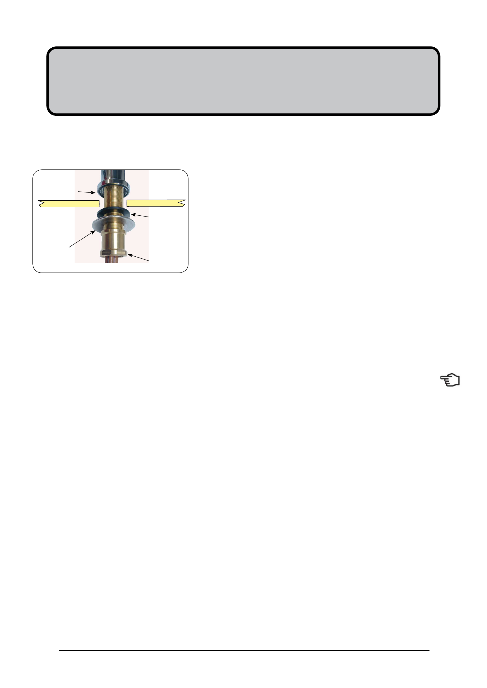
O-RING
LOWER
RUBBER
WASHER
WASHER
NUT
1.1- Installing the Tap
Position and install the carafe filler at the back of the sink or on the Font,
where there is a minimum 52mm wide flat area within the draining area
of the sink.
Make sure the selected position allows the carafe filler spout to overhang
the sink bowl.
Use a 25mm sheet metal punch to create a neat hole without burrs.
Remove the large nut with the stainless steel and rubber washers from
the base of the carafe filler, leaving the rubber-sealing ring (O-ring) in
place.
Fit the carafe filler and seal to the sink, oriented so both the operating
levers are easily accessible.
Slide first, the rubber washer and then the brass washer, followed by the
nut, over the tubes from under the sink, and tighten the nut to secure the
carafe filler firmly into place.
NOTE: The Clear tube must be trimmed to length and blocked with
the JG fitting supplied.
Page 7

2.1 Ventilation for All Models
Proper air circulation must be provided for all Boiling and Chilled models. The system will operate correctly only if the recommended
air gaps are achieved during Installation. The minimum requirement is for a 50mm air gap either side and 300mm above of the
undersink unit.
It is important that the 4mm door buffers (For all installations ) are fitted to the inside edge of the cupboard door to allow suficient
air circulation inside the cupboard. (See the diagram below).
IMPORTANT: See section 4 for clearances.
•
When installing air flow ducts, the following tools will be required:
•
Jigsaw and 12mm Drill
•
Keyhole or Wall Board saw.
Section 2
Ventilation
Min 300mm
470mm
4 min.
Buffer Pad
Clear Gap
Installation & Operating Instructions - 89914 - Zip ChillTap Sparkling - Jan 2016 v1.04 Page 7 of 20
Page 8

Ventilation
Air inlet vent position
Airflow through the cupboard
B
D
Cool air IN
Warm air
OUT
Door outlet vent
1. Drill four pilot holes 12mm
dia.
2. Finish the cutout using a
jig saw and keyhole or Wall
Board saw
If the air flow, using the silicon door buffers, is insufficient, it will be necessary to fit a standard HydroTap vent kit, which ensures
heat dissipation through natural convection via installed vents.
For high use applications, where the cupboard space temperature is near 35°C, or higher, the inlet vent (See Item B below) and
silicon buffers, need to be fitted. If the airflow is still insufficient to maintain normal operating temperatures then the inlet vent and
door outlet vent (See item D below) will need to be fitted.
Alternatively a fan kit may be installed, using the AUX din plug of the right hand side of the appliance (Contact your local service
centre for availability).
Note: The vent kit has to be installed in a way that allows air to be drawn in from the bottom of the cupboard and expelled through
the top of the cupboard. Therefore placement of the outlet vent should be towards the top of the door or on the side of the
cupboard.
2.2
The following instructions are critical if there is insufficient cupboard air circulation.
Cutout details
Page 8 of 20 Installation & Operating Instructions - 89914 - Zip ChillTap Sparkling - Jan 2016 v1.04
Page 9

Typical Cut out procedure for
B
Ventilation
Cutout deatils
Air inlet vent
1. Mark out and cut the air inlet and door outlet holes as shown
2. Ensure the air inlet vent and air outlet vent are positioned at opposite ends of the same
cupboard space.
3. Fit the inlet vent, as shown and secure with 5 screws
4. If required, fit the outlet vent, as shown in the hottest part (top) of the cupboard and
secure with 4 screws
B
D
Installation & Operating Instructions - 89914 - Zip ChillTap Sparkling - Jan 2016 v1.04 Page 9 of 20
Page 10

Section 3
CO
2
Cylinder
WARNING:
This cylinder mus be installed in an open plan area or in an enclosed room, with a volume no less than 20m3. If more than 1
gas cylinder containing CO2 is present within the same location, the recommended ventilated area should be in proportion to the
number of gas cylinders stored in that location.
A ventilated area is a non-enclosed area which could include the kitchen, living room etc.
See gas bottle and MSDS sheet for a complete list of warnings. (See: www.zipindustries.com)
3.1
Secure the cylinder mounting:
Secure the gas bottle supplied to a suitable wall, within 1 metre of the unit, in an upright position. This is done by screwing the
metal plate holding the Velcro strap to a cupboard wall, 200mm above the floor or base of the cupboard. Make sure the gas bottle
can stand before securing to the wall.
Due to regulatory requirements the gas bottle must be stored securely and in an upright position.
3.2
Connect the regulator:
Make sure the regulator knob is turned fully anti-clockwise to the end-stop before fitting. Fit the regulator to the gas bottle. Be aware
that some CO2 may be discharged from the connection to the regulator as the bottle and the regulator are be assembled together.
Any CO2 released will be cold. Continue to screw on the regulator to stop this leakage.
3.3
Connect the gas hose:
Connect the braided gas hose to the top of the undersink unit via the John Guest fitting marked ‘Gas IN’ Then connect the
threaded end to the regulator, taking care not to lose the plastic olive located inside the threaded nut. To turn the gas ON, rotate
the regulator knob clockwise and adjust to 2.7-3.0 bar (270-300kPa). The arrow should sit in the green section of the regulator
gauge; it should not fall in the red or yellow sections.
Page 10 of 20 Installation & Operating Instructions - 89914 - Zip ChillTap Sparkling - Jan 2016 v1.04
Page 11

Section 4
Undersink Unit Installation
Installation & Operating Instructions - 89914 - Zip ChillTap Sparkling - Jan 2016 v1.04 Page 11 of 20
CO2 Cylinder
Filter
Filter Head
Isolation Valve
(Not Supplied)
Carafe Filler
Vent pipe
blocked off
General instructions for
John Guest connections
NOTE: Ensure all John Guest
tube ends are cut clean and
square.
John Guest (JG) fittings
Page 12

Installation & Operating Instructions - 89914 - Zip ChillTap Sparkling - Jan 2016 v1.04 Page 12 of 20
# Installation Instructions continued
4.1 - Chiller Installation
Place the chiller unit into the cupboard with the proposed outlet tap position as close
as possible, to minimise the length of tubing exposed between the chiller unit and
the outlet tap. (The tubing length is limited to 1000mm)
Allow at least 50mm around the chiller unit to permit free airflow. Both the top and
the front of the chiller must remain accessible for servicing purposes.
4.2 - Hose and Tube connections:
NOTE: You must separately supply and install an isolation valve (not supplied) in
the supply line before the connection to the product.
Connect the tube to the isolation valve (via the JG fitting). For best results we
recommend a minimum static pressure of 250kPa (2.5 bar).
Mains Connection (with chiller inlet):
Connect the tube from the isolation valve to the JG fitting on top of the undersink
unit, marked MAINS IN.
Chilled Still Connection:
Remove the plug fitted into the connection marked “Still Outlet“ by first depressing
the collet and simultaneously pulling out the plug. Measure and trim the 1/4” blue
tube from the carafe tap to the JG fitting marked “Still Outlet” on the top rear of the
chiller unit. Before making connection, insulate the tube with the loose length of the
foam insulation, trim the insulation to the correct length, which is about 5-10mm
shorter than blue tube. Push the blue tube fully into the John Guest fitting marked
“Still Outlet”. Make sure all connections to John Guest fittings are pushed in past the
“O”ring to full depth.
Chilled Sparkling Connection:
Remove the plug fitted into the connection marked “Sparkling Outlet“ by first
depressing the collet and simultaneously pulling out the plug. Similarly, measure
and trim the 1/4” white tube from the carafe tap to the JG fitting marked “Sparkling
Outlet” on the top rear of the chiller unit. Before making connection, insulate the tube
with the loose length of the foam insulation, trim the insulation to the correct length,
which is about 5-10mm shorter than white tube. Push the white tube fully into the in
John Guest fitting marked “Sparkling Outlet”. Make sure all connections to JG fittings
are pushed in past the “O”ring to full depth.
Use the tubing clamps to neat up the installation.
The tap connection is now complete.
IMPORTANT: The Clear tube is non functional. However, it must be trimmed
to length and blocked with the JG fitting supplied, otherwise water will leak from it
whenever the tap is operated.
Note: To avoid water leaks,
take care when bending rigid
plastic tubing. The tube must not
be kinked or crushed around a
bend, as the tube may containing
water under pressure. Therefore
be careful not to nick, scratch
or damage the tube during
installation.
Page 13

CO2 pressure set zone: 2.7- 3.0 bar
After replacing a bottle or after making a
gas connection:
Stage1:
1. Turn the gas OFF
2. Using soapy water applied with a sponge, or with a
brush, cover all of the gas joints with a liberal amount of
suds.
3. Alternatively, use a leak detecting spray.
Stage 2:
1. Turn ON the gas
2. Inspect the joint for leaks
3. If any bubbles appear, the joint will need to be resealed.
Soap test
Faulty seal joint
Installation & Operating Instructions - 89914 - Zip ChillTap Sparkling - Jan 2016 v1.04 Page 13 of 20
4.3 - CO2 Gas Connection:
Connect the braided hose to the fitting marked ‘CO2 IN’ on top of the undersink
unit. Turn on the regulator clockwise and adjust to 2.7-3.0 bar. The arrow
should sit in the green section of the regulator gauge; it should not fall in the
red or yellow sections.
Using soapy water perform a leak test. Apply the soapy water to the gas
connections using a sponge. If any bubbles appear and grow, there is a gas
leak at the connection. Clean away the soapy residue and tighten or refit the
leaking connection. Make sure the regulator is turned off when tightening or
refitting the leaking connection.
Once satisfied that there are no leaks and with the regulator set at 2.7-3.0 bar,
ensure the gas bottle is securely mounted in an upright position, using the
velcro strap.
NOTE: Care must be taken when working with high pressure carbon
dioxide, and in no cases should the normal operationg pressure of 2.7-3.0 bar,
be exceeded.
WARNING:
This cylinder must be installed in an open plan area or in an enclosed room,
with a volume no less than 20m3. If more than 1 gas cylinder containing CO2 is
present within the same location, the recommended ventilated area should be
in proportion to the number of gas cylinders stored in that location.
A ventilated area is a non-enclosed area which could include the kitchen, living
room etc.
See gas bottle and MSDS sheet for a complete list of warnings.
(See: www.zipwater.com)
NOTE: When
removing plug from
end of braided hose,
take care not to lose
plastic olive.
Installation Instructions continued
Page 14

Page 14 of 40 802005 - Sparkling HT-BCS; CS; AIO; Residential- Installation Instructions - June 2015 - v2.01
Section 5
Commissioning
Chilled filtered water
(blue)
Sparkling filtered water
(white)
Note: After dispensing sparkling water, a small amount will remain in the carafe
filler. If the next drink is to be still water and you do not wish any trace of sparkling
water, the still water should be running for approximately 1 second before filling your
glass or bottle. The same is applicable if still water is dispensed prior to dispensing
sparkling water.
5.1 - Test and Commission:
Do NOT turn power or water on to the unit. The carbonator must be purged first with
the CO2 gas. Failure to do so will result in poor tasting water. With the regulator set
to 2.7-3.0 bar, turn the sparkling water lever on (white ringed lever) The CO2 will
start to run out of the tap. Gas will purge or escape from the tap at this point. Let it
run for approximately 5 seconds to completely fill the tank. Close the sparkling lever
by rotating back to upright.
Turn on the still water lever (blue ringed lever) then turn on the water supply to the
unit. First air, then water will flow from the tap. Allow the water to continue to flow for
about 7.5 litres, which is required to activate the filter. Once this has been done turn
off the still water lever.
Connect the power and turn ON at the GPO and at the side of the undersink unit.
The compressor and fan will start, and the water pump will operate for
approximately 20 seconds to fill the carbonator vessel.
After approximately 5 minutes, the compressor and fan will stop as the chiller has
reached its normal operating temperature.
To achieve an optimal level of carbonation, it is beneficial to purge the carbonation
vessel again by isolating the water and electrical supply, and opening the sparkling
lever on the tap until gas is expelled for approximately 5 seconds. Close the tap
and reconnect water and power. Wait 20 seconds and the sparkling water should be
ready for use.
At this time check to ensure the pressure gauge is still reading 2.7-3.0 bar. If not,
adjust the regulator accordingly.
Important: Excessive flow rates of carbonated water will result in poor drink
quality. It is recommended that the flow rate for carbonated water should be
approximately 1.2-1.8 litres/minute. If this is incorrect, it must be adjusted by a
qualified service technician.
The lever on the right (Blue rings) is used for chilled still filtered water and the lever
on the left (White rings) is used for chilled sparkling filtered water.
Chilled water is obtained by rotating the lever on the right, to a horizontal position.
The water is chilled by a refrigeration unit fitted within the cabinet stand, under the
basin.
With the carafe tap, you can obtain chilled water within the rated capacity, for as
long as you leave the lever in the open (horizontal) position. When finished, return
the lever to the OFF (upright) position.
Sparkling water is obtained in the same way as the chilled water, by rotating the
lever on the left hand side of the carafe tap.
ROTATE
Operation
Page 15

Section 6
Maintenance
Installation & Operating Instructions - 89914 - Zip ChillTap Sparkling - Jan 2016 v1.04 Page 15 of 20
Water Filter Replacement
NOTE: For safe operation, the filter cartridge should be replaced every 6-12
months, or earlier if you notice a persistent reduction in water pressure from the
appliance or an unpleasant taste or odour in the water.
Water Filter Change:
1. Turn off the water and power supply to the unit.
2. Turn the still water lever (blue ringed lever) on, to release any water
pressure in the unit. Once water has stopped running from the tap turn off
the lever.
3. Turn the filter clock wise and gently pull the cartridge down. The cartridge
should release from the filter head. Dispose of the filter cartridge
responsibly. Clean any water that has pooled below the filter head.
4. Fit a new filter by turning filter anticlockwise and gently pushing up. The
filter will click or lock into place.
5. Turn the still water tap on.
6. Turn on the water supply to the unit. Allow 7.5 litres to flow from the
outlet.
7. Turn off the still water lever.
8. Turn on the power supply to the unit.
Warning
Not changing filtration cartridges when required, may cause the water to become
biologically unsafe.
If the Zip HydroTap is switched off for a long period of time (e.g. More than a
weekend), run water through the chilled water outlet for at least 5 minutes before
consumption.
Use only a Zip Filter to match that used with this ChillTap (if fitted). Replacement filter
cartridges can be obtained through plumbing suppliers or directly from Zip.
Replacement instructions come with the filter cartridges.
Before attempting to disconnect or remove the filter cartridge from the housing,
isolate (turn off) the water supply prior to the filter system, and then relieve the
system pressure by operating the chilled water outlet tap until the water ceases to
flow.
Page 16

Page 16 of 40 802005 - Sparkling HT-BCS; CS; AIO; Residential- Installation Instructions - June 2015 - v2.01
Air Filter Change:
The Zip HydroTap air filter is conveniently located on the outside of the condenser.
The filter screen is a sliding fit in the plastic housing on the left hand side of the under
sink unit. The screen may be removed for cleaning, by sliding it forward. This needs
to be inspected at least quarterly, cleaned and replaced if damaged.
Note
:
For best performance the unit should only be operated with a clean air filter
screen, correctly fitted in place. Maintain, at least, a 50mm air gap in front of the
screen at all times. Take care not to allow cloths or other soft materials to accidentally
block the air inlet.
Slide to remove
Filter
CO2 Gas Bottle Replacement
Gas Bottle Replacement:
1. Turn off the water and power supply to the chilled sparkling unit.
2. Turn off the regulator on top of the bottle. The regulator has a left hand
thread, to turn off, turn anticlockwise until shut.
3. Remove the CO2 bottle from its mounting and unscrew the bottle from the
regulator. The braided hose may be left connected to the regulator, or, for
convenience, removed and refitted to the regulator and new bottle.
4. Connect the new bottle to the regulator. Be aware that some CO2 may be
discharged from the connection to the regulator when the bottle and the
regulator are assembled together. Any CO2 released will be cold.
5. Ensure the braided hose is correctly fitted to the regulator, with the sealing
olive in place, before turning on the gas.
6. Turn the regulator on and adjust to 2.7- 3.0 bar.
7. Turn the sparkling lever to the on position. Leave it on until all the water
has been purged through the tap. Let the tap run for a further 10 seconds to
purge the CO2 through the tank. Turn off the sparkling lever.
8. Turn on the cold water supply first and then the power supply.
9. Wait 20 seconds and then turn on the sparkling lever and wait for water to
start to come through.
10. Dispense some sparkling water from the tap. Perform a taste test.
Service
There are no user serviceable parts but there are dangerous voltages present
within the unit. All service work must only be carried out by a suitably qualified and
experienced service person.
Before calling for service, check that both the water and electricity supplies are turned
‘ON’ and OK.
Call a licenced electrician, plumber, or Zip for a free call in Australia on 1800638-633, for assistance, service, spare parts, or enquiries.
Maintenance
Page 17

Installation & Operating Instructions - 89914 - Zip ChillTap Sparkling - Jan 2016 v1.04 Page 17 of 20
# Trouble Shooting
Symptom Possible Cause Responsibility Solution
No still water
No sparkling water
Poor levels of
carbonation in drinks
Mains water not
connected or turned on
Water pressure regulator
failed
Unit frozen up
No CO2 pressure
Internal fault
Incorrect CO2 pressure
Air in carbonation can
Residue in carbonation
can
Carbonation can is
overfilled
Connect or turn on water supply.
Contact local Zip Service Provider.
Contact local Zip Service Provider.
Check pressure of CO2 bottle. Regulator to be set
to 270kPa.
Contact local Zip Service Provider.
Check CO2 regulator. Supply pressure should be
270kPa (2.7 bar), adjust or replace as necessary.
Purge system as described on page 9 “Gas Bottle
Replacement”.
Contact local Zip Service Provider.
Contact local Zip Service Provider..
Prior to any fault finding, please ensure all water connections to the chiller are sound and that the incoming water supply is
turned on. Also ensure that all electrical connections to the chiller are secure and that the chiller has had adequate time to
cool down.
User or Service
Technician
Service
Technician
Service
Technician
User
Service
Technician
User
User
Service
Technicain
Service
Technician
Page 18

Installation & Operating Instructions - 89914 - Zip ChillTap Sparkling - Jan 2016 v1.04 Page 18 of 20
Trouble Shooting continued
Warm drinks
No power
Thermostat faulty or out of
calibration.
Insufficient cooling air flow
through the fridge
Fridge failure
Rated chilled water capacity
has be expended
Restore power to the unit.
Contact local Zip Service Provider.
Contact local Zip Service Provider.
Contact local Zip Service Provider.
Allow unit sufficient time to recover.
Symptom Possible Cause Responsibility Solution
In order to help preserve our environment we ask that you dispose of this
product correctly. Please contact your local city council for collection centre
details.
End of Life Disposal
Never use strong, corrosive or abrasive cleaning materials on the Zip ChillTap.
Wipe clean the outer surfaces with a sponge or a soft cloth using a mild soap
and water.
The louvres on the sides of the chiller unit need to be kept free of dust and lint
to permit free flow of air through the vents. They should be checked regularly, at
least monthly, and dusted or vacuumed.
Sanitising cabonation can may be required when the quality of sparkling water
deteriorates. Please contact your local Zip service provider.
User or Service
Technician
Service
Technician
Service
Technician
Service
Technician
User
Cleaning
Page 19

Installation & Operating Instructions - 89914 - Zip ChillTap Sparkling - Jan 2016 v1.04 Page 19 of 20
Notes
Page 20

Installation & Operating Instructions - 89914 - Zip ChillTap Sparkling - Jan 2016 v1.04 Page 20 of 20
Head Office
Zip Heaters (Aust) Pty. Ltd.
ABN: 46 000 578 727
67 Allingham Street
Condell Park NSW 2200
Postal: Locked Bag 80
Bankstown 1885 Australia
Website: www.zipwater.com
Facsimile (02) 9796 3858
Telephone(02) 9796 3100
Free Call 1 800 638 633
Contact Details
WMKA21821
ATS 5200.105
As Zip policy is one of continuous product improvement, changes to
specifications may be made without prior notice. Images in this booklet have
been modified and may not be true representations of the finished goods.
 Loading...