

Page 1
Installation and Operating Instructions
Zip Filter Tap
Cold Water Filtration (unchilled)
Affix Model Number Label Here
801085
Zip Filter Tap - Installation & Operating Instructions - 801085 - November 2012 v1.00 Page 1 of 8
Page 2
R
Please read all Warnings, Installation Requirements and Installation Instructions before installing any
Zip Filter Tap.
These appliances are not intended for use by persons (including children) with reduced physical,
sensory or mental capabilities, or lack of experience and knowledge, unless they have been given
supervision or instruction concerning use of the appliances by a person responsible for their safety.
Children should be supervised to ensure they do not play with the appliances.
The units are for indoor use only and must not be exposed to the elements of nature.
These units must not be positioned in an area that may be cleaned by a water jet. These units must not be cleaned by a
water jet.
WARNING: For correct operation of this appliance it is essential to observe the manufacturer’s instructions.
Read These Warnings First
Precautions
The plumbing installation must be done in accordance with local Water Authority regulations and these Installation
Instructions.
As the installer, it is your responsibility to supply (if necessary) and install all valves as required by local regulations and
relevant standards.
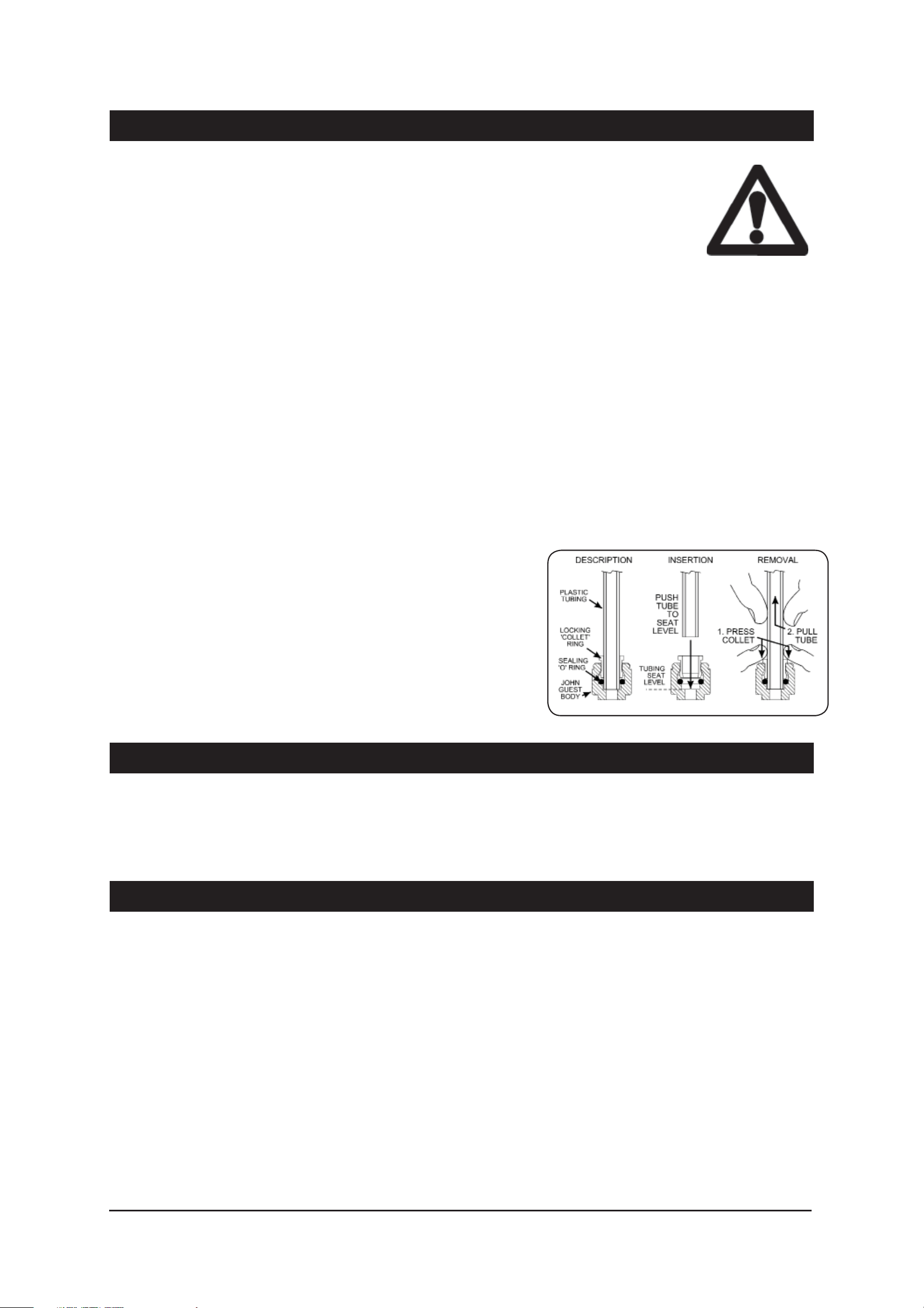
Correct Use of JG Quick Connect Fittings
John Guest quick connect fittings and hoses are used in Zip products.
Note insertion and removal details for JG fittings using plastic tubing as
seen in the adjacent diagram.
NB: Be sure to cut the tube squarely with a sharp knife or tube cutter.
Shake out and remove any swarf or debris.
Installation Requirements
• Operating temperatures 5º C - 35º C.
• Water pressure 172 kPa - 700 kPa (0.172 MPa -0.7 MPa)
It is the installers responsibility to ensure the installation complies with AS/NZS3500.1, AS/NZS3500.2, AS/NZS3500.4.1,
AS/NZS3500.4.2 and local water authority regulations.
Installation Instructions
Installing the Filtration Unit
The filtration unit should be mounted in a convenient position in the cupboard, to allow for ready and easy access during
filter changes.
Usually the side of the cupboard, near the door, is most suitable. However, the length of the tubes from filter to carafe
tap and from water supply to filter need to be considered when selecting a suitable position to mount the filter head.
Using the two screws provided, screw the filter head to the inside of the cupboard, allowing 270 mm minimum clearance
between the underside of the filtration head and any obstructions like shelves, etc.
Write the installation date on the filter cartridge. Fit the cartridge into the housing. The model you have may appear
slightly different to that illustrated, however, operation and function is identical.
Align the tabs of the cartridge with the filter housing and insert it into the socket. Turn the cartridge a quarter turn to the
right until it stops and locks into position.
Check that the direction of flow on the filter head is correct.
Page 2 of 8 Zip Filter Tap - Installation & Operating Instructions - 801085 - November 2012 v1.00
Page 3
# Installation Instructions
1
1
2
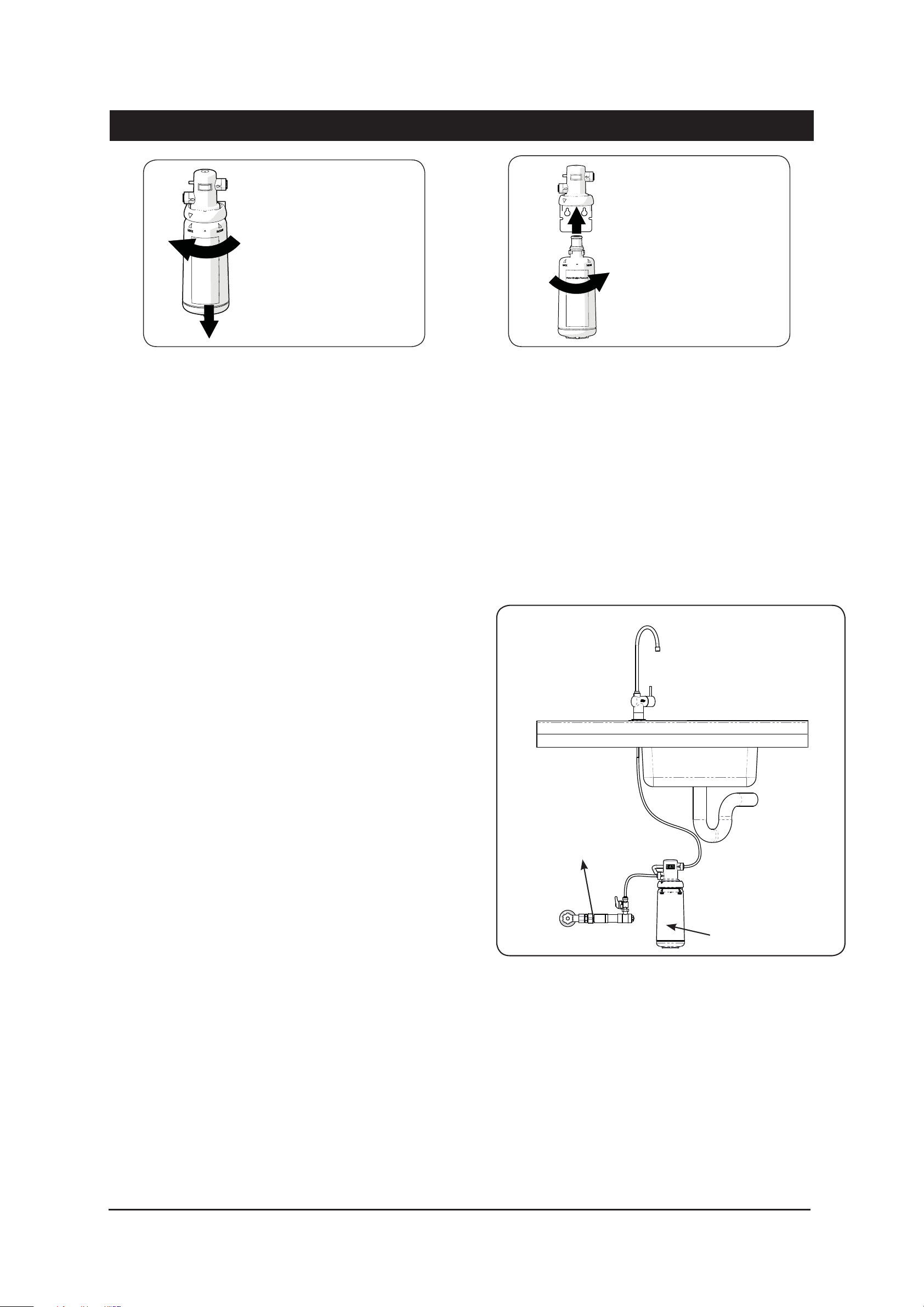
Filter cartridge removal
2
Filter cartridge insertion
Installing the Filter Tap
Position the Filter Tap at the back of the sink where there is a 45 mm wide flat area within the draining areas of the
sink. The recommended position is over one corner of the bowl. Make sure the selected position allows the spout to
overhang the sink bowl.
The cutout size is 25 mm. Mark the centre of the new Filter Tap position on the sink with a centre punch. Drill out the
centre of the hole to allow the screw of a sheet metal punch to pass through the sink. Use a 25 mm sheet metal punch
to neatly cut the hole.
Remove the nut and washer from the base of the Filter Tap, and pass the tubing through the sink until the Filter Tap sits
upright within the hole you just created in the sink surround.
Orientate the Filter Tap so that the activating lever is away from
the sink bowl. Slide on the washer and nut from beneath the sink,
Installation Diagram
and tighten the nut to secure the Filter Tap firmly into place.
Take care, when bending plastic tubing, to prevent it from kinking
or crushing on a bend.
Do not connect the tubes in any other arrangement than that
described here. The filter cartridge and the Filter Tap have
directional flow connections that will not work if connected
incorrectly. Incorrect installation will void any product warranty.
Note that the flow direction of the filter housing is indicated on
the filter housing.
Double Non Return - DNR
and pressure limiting Valve
Measure and cut the tube from the Filter Tap to length so that
it runs around the back of the cupboard to the outlet side of the
filter housing. Use a tube cutter to cut the end off the tubing neat
and square, so that there are no dags or rough edges. Shake the
tube vertically to allow any debris to fall out of the tube before
Filter
inserting it into the filter head.
Push this end of the blue tube firmly into the John Guest socket on the outlet side of the filter head.
It must push in at least 10 mm. Test the connection by trying to pull the tube out. If it comes out, re-insert it so that it
won’t come out when pulled against.
Zip Filter Tap - Installation & Operating Instructions - 801085 - November 2012 v1.00 Page 3 of 8
Page 4

#
Installation Instructions
Installing the DNR Multifunction Valve
The DNR valve must be inserted into the tube between the main isolation valve
and the filter cartridge. Ensure the flow is in the correct direction.
The DNR valve must be connected downstream of an accessible isolation tap.
The 3/4”F- BSP threaded section on the inlet end of the DNR valve may be
connected directly to an isolation tap.
NOTE: The centre of the 3/4” fitting may be removed with an 8mm allen key to
allow for direct connection to a 1/2” BSP Tap. Remember to re-fit the strainer
and sealing washer.
Alternatively, the DNR valve may be positioned so that it can be seated into a
retaining clip screwed to the cupboard wall.
Take the one metre tube from the filter kit.
Meaure and cut the tube from the DNR valve to length so that it runs around the back of the cupboard to the inlet side of
the filter housing. Leaving a little extra slack in this line for the connection of the DNR valve.
3/4” FBSP
Water Inlet
1/2” FBSP
Black sealing plug
Strainer and
sealing washer
Pos.B ( Alternative outlet )
Service valve
To filter
Pos. A
Insert the tube end into the (JG) fitting on the side of the DNR valve.
Insert the other end of tube into the (JG) fitting on the Inlet side of the filter head. Note the directional arrows on the body
of the Valve. It must end up connected so that they point in the direction of the Flow. (see Installation Diagram on Pg 3.)
The valve may be positioned vertically or horizontally.
When mounted horizontally the service tap may be fitted to one of two outlet port positions i.e axially in line (Pos A) or at
90 degrees (Pos B). When changing the outlet position remember to refit the black sealing plug to the un-used port.
Filling the system
Turn ‘on’ the water supply. Check the connections for leaks. Repair any found.
The filter and tubing are full of air until purged, and the filter cartridge requires activation when first installed. Flip up the
operating lever on the Zip Filter Tap for a minimum of five minutes until all of the air has been purged from the system,
and the cartridge has time to become fully activated.
Every time the filter cartridge is replaced, repeat this procedure of a five minute flush to activate the new cartridge
properly.
Page 4 of 8 Zip Filter Tap - Installation & Operating Instructions - 801085 - November 2012 v1.00
Page 5

#
NOTE: When flushing the system, some black particles may be released into the water. This is normal. The water will
become clear after the first few litres.
Complete the installation and leave these instructions with client.
Installation Instructions
Service
All service work must only be carried out by a suitably qualified and experienced service person.
Before calling for service, check the water supply is turned ‘ON’ and OK.
Call Zip in Australia on 1800-638-633 for assistance, service, spare parts, or enquiries.
# Filter Replacement
Not changing cartridges when required may cause the water to become biologically unsafe.
Thoroughly flush the water through if the filter tap has not been used for more than 12 hours. For safe operation, the
filter cartridge should be replaced at least every 6-12 months, or earlier if you notice a persistent reduction in water
pressure from the Filter Tap, or an unpleasant taste or odour in the water.
Use only a Zip filter cartridge to match that of your Filter Tap. Replacement cartridges can be obtained through plumbing
suppliers or directly from Zip.
When replacing your Zip filter cartridge, replacement instruction will be provided with your replacement cartridge kit.
# Operating Procedures
Operating
You can obtain filtered water within the rated capacity for as long as you rotate the
lever. In the upright position the tap is off, when the lever is rotated anticlockwise
water will flow. Water will continue to flow until the lever is returned to the upright
position.
Cleaning
ROTATE
Never use strong, corrosive or abrasive cleaning materials on the Zip Filter Tap. Wipe
the outer surfaces clean with a sponge or a soft cloth using a mild soap and water.
Troubleshooting
Problem Cause Remedy
No water at outlets Water not connected Connect and turn on water
Poor flow at outlet Blocked filter Replace filter
Zip Filter Tap - Installation & Operating Instructions - 801085 - November 2012 v1.00 Page 5 of 8
Page 6

Performance Data Part Number 91289
Performance Data Sheet
Use Replacement Catridge 91289
The concentration of the indicated substances in water entering the system was reduced to a concentration less than or equal to the
permissible limit for water leaving the system as specified in NSF/ANSI Standard 42 and NSF/ANSI Standard 53.
Capacity: 3,785 litres Contaminant Reduction Determined by NSF testing.
Test Conditions: pH7.5, Pressure: 415 kPa, Flow Rate: 1.9L/min
Substance
Reduction
Chlorine Taste
and Odor
Cyst* 140,000
Lead pH @6.5 0.150
Lead pH @8.5 0.150
* Based on the use of Cryptosporidium parvum oocysts
Average
Infl uent
2.0 mg/L 2.0 mg/L ±10% 97.3% 0.05 mg/L N/A 5.0 mg/L 50% J-00109688
cysts/L
mg/L
mg/L
NSF/ANSI specifi ed
Challenge Concentration
Minimum 50,000 cysts/L >99.99% 3 cyst/L N/A 1 cyst/100 L 99.95% J-00109693
0.15 mg/L ± 10% >99.3% 0.001 mg/L 0.010 mg/L 0.01 mg/L N/A J-00109691
0.15 mg/L ± 10% 99.3% 0.001 mg/L 0.010 mg/L 0.01 mg/L N/A J-00109692
Application Guidelines/ Water Supply Parameters
Service Flow 1.9 Ipm
Water Supply Potable Water
Water Pressure 172 - 862 kPa
Water Temperature 4.4ºC - 38ºC
Avg %
Reduction
Average
Product
Water
Concentration
NSF Max
Permissible
Product Water
Concentration
Australian/ New Zealand
(AS/NZS Standard 3497)
Max Permissible Prod-
uct Water Concentration
NSF
Reduction
Require-
ments
System tested and certifed by NSF
International against NSF/ANSI Standard
42 and Standard 53 for the reduction of
substances as listed below according to
Standard 42 and Standard 53.
NSF Test
Report
It is essential that the manufacture’s recommended installation, maintenance and filter replacement requirements be carried out for the
product to perform as advertised. See installation Manual for details.
Note: While the testing was performed under standard laboratory conditions, actual performance may vary.
WARNING
To reduce the risk associated with ingestion of contaminants:
Do not use with water that is microbiologically unsafe or of unknown quality without adequate disinfection before and after the system.
Systems certifi ed for cyst reduction may be used on disinfected water that may contain fi lterable cysts.
EPA Establishment Number 070595-MEX-001
CAUTION
To reduce the risk associated with property damage due to water leakage:
• Read and follow Use Instructions before installation and use of this system.
• Installation and use MUST comply with all state and local plumbing codes.
• Do not install if water pressure exceeds 862 kPa. If your water pressure exceeds 551.68 kPa, you must install a pressure limiting
valve. Contact a plumbing professional if you are uncertain how to check your water pressure.
• Do not install where water hammer conditions may occur. If water hammer conditions exist you must install a water hammer
arrester. Contact a plumbing professional if you uncertain how to check for this condition.
• Do not install on hot water supply lines. The maximum operating water temperature of this filter system is 38ºC.
• Protect filter from freezing. Drain filter when temperatures drop below 4.4ºC.
• The disposable filter cartridge must be replaced every 12 months or at the specified service cycle, or sooner, if a noticeale reduction
in flow rate occurs.
Page 6 of 8 Zip Filter Tap - Installation & Operating Instructions - 801085 - November 2012 v1.00
Page 7

Notes
Zip Filter Tap - Installation & Operating Instructions - 801085 - November 2012 v1.00 Page 7 of 8
Page 8

Contact Details
Head Office
Zip Heaters (Aust) Pty. Ltd.
ABN: 46 000 578 727
67 Allingham Street
Condell Park NSW 2200
Postal: Locked Bag 80
Bankstown 1885 Australia
Website: www.zipheaters.com
Facsimile: (02) 9796 3858
Telephone: (02) 9796 3100
Free Call: 1 800 638 633
As Zip policy is one of continuous product improvement, changes to
specifications may be made without prior notice. Images in this booklet have
been modified and may not be true representations of the finished goods.
WMKA25287
AS/NZS 3497
The term “Zip” is a registered trade mark of Zip Heaters (Aust) Pty Ltd.
Zip Filter Tap - Installation & Operating Instructions - 801085 - November 2012 v1.00 Page 8 of 8
 Loading...