

Page 1
Electronically controlled instantaneous water heater
MCX: 27300, 27400 and 27600 models
Installation instructions
These appliances deliver water not exceeding 50 ºC in accordance with AS3498.
Page 2
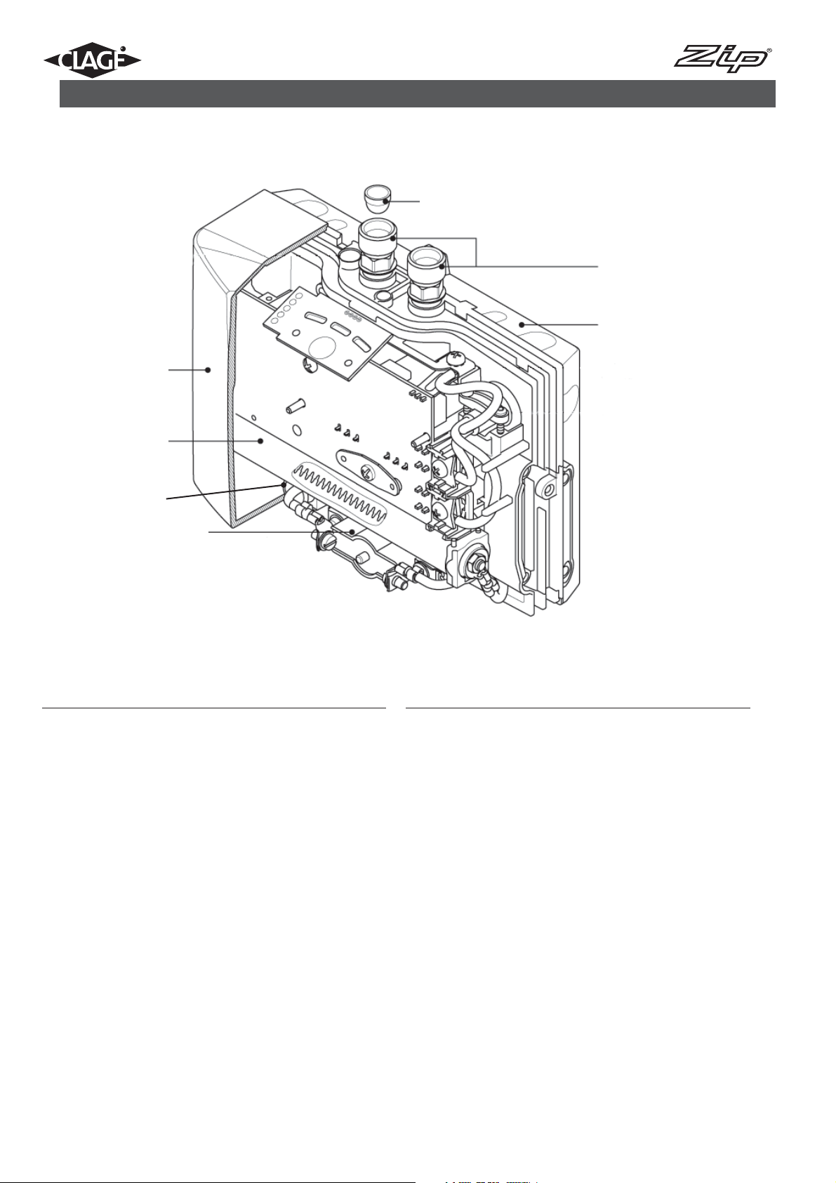
1. Overview
When ordering spare parts, please always specify the appliance model and serial number.
4
1
2
7
5
6
3
Pos. Part.-No. Description
1 Hood with control panel
2 801119 MCX heating cartridge 3.5 kW /230V
801120 MCX heating cartridge 4.4 kW /230V
801121 MCX heating cartridge 5.7 kW /230V
3 MCX Safety temperature limiter (STB) with
modification instructions, contact fitting, seals etc.
• 2-pole
• 1-pole
4 801122 MCX Filter
5 MCX water connector-set with two water connectors
and seals (mounted and greased) fastening safety
earthing terminal and filter
Pos. Part.-No. Description
6 MCX complete fixing set (wall bracket with screws
and dowels)
7 801123 Temperature sensor (polarity protection)
not shown:
MCX 3 mains cable with earthed plug,
cable seal and strain relief
MCX 4 mains cable (without plug), cable seal
and strain relief
MCX 6 mains cable (without plug), cable seal
and strain relief
MCX set of small spare parts (seals, nozzle for
cable entry, terminal, installation grease, screws,
wheel nut & discs)
Parts in Bold Type are available as Spare Parts.
Other parts are available on request.
2
Instructions for installer - 9120-15004 - MCX - 801053 - March 2013 v1.01
Page 3
Contents
1. Overview . . . . . . . . . . . . . . . . . . . . . . . . . . . . . . . . . . . . . . . . . . . . . . . . . . . . . . . . . . . . . . . . . . . . . . . . . . . . . . . . . . . . . . . . . . . . . . . 2
2. Environment and recycling . . . . . . . . . . . . . . . . . . . . . . . . . . . . . . . . . . . . . . . . . . . . . . . . . . . . . . . . . . . . . . . . . . . . . . . . . . . . . . . . . . 3
3. Safety instructions . . . . . . . . . . . . . . . . . . . . . . . . . . . . . . . . . . . . . . . . . . . . . . . . . . . . . . . . . . . . . . . . . . . . . . . . . . . . . . . . . . . . . . . . 4
4. Technical specifications . . . . . . . . . . . . . . . . . . . . . . . . . . . . . . . . . . . . . . . . . . . . . . . . . . . . . . . . . . . . . . . . . . . . . . . . . . . . . . . . . . . . 5
5. Typical Installations . . . . . . . . . . . . . . . . . . . . . . . . . . . . . . . . . . . . . . . . . . . . . . . . . . . . . . . . . . . . . . . . . . . . . . . . . . . . . . . . . . . . . . . . 6
6. Description of appliance . . . . . . . . . . . . . . . . . . . . . . . . . . . . . . . . . . . . . . . . . . . . . . . . . . . . . . . . . . . . . . . . . . . . . . . . . . . . . . . . . . . . 8
7. Installation . . . . . . . . . . . . . . . . . . . . . . . . . . . . . . . . . . . . . . . . . . . . . . . . . . . . . . . . . . . . . . . . . . . . . . . . . . . . . . . . . . . . . . . . . . . . . . 8
8. Commissioning . . . . . . . . . . . . . . . . . . . . . . . . . . . . . . . . . . . . . . . . . . . . . . . . . . . . . . . . . . . . . . . . . . . . . . . . . . . . . . . . . . . . . . . . . . 12
9. Flow rate adjustment . . . . . . . . . . . . . . . . . . . . . . . . . . . . . . . . . . . . . . . . . . . . . . . . . . . . . . . . . . . . . . . . . . . . . . . . . . . . . . . . . . . . . 12
10. Removing the appliance from the wall bracket . . . . . . . . . . . . . . . . . . . . . . . . . . . . . . . . . . . . . . . . . . . . . . . . . . . . . . . . . . . . . . . . . 13
11. Maintenance . . . . . . . . . . . . . . . . . . . . . . . . . . . . . . . . . . . . . . . . . . . . . . . . . . . . . . . . . . . . . . . . . . . . . . . . . . . . . . . . . . . . . . . . . . 14
12. Fault finding . . . . . . . . . . . . . . . . . . . . . . . . . . . . . . . . . . . . . . . . . . . . . . . . . . . . . . . . . . . . . . . . . . . . . . . . . . . . . . . . . . . . . . . . . . . 14
13. Notes . . . . . . . . . . . . . . . . . . . . . . . . . . . . . . . . . . . . . . . . . . . . . . . . . . . . . . . . . . . . . . . . . . . . . . . . . . . . . . . . . . . . . . . . . . . . . . . . 15
2. Environment and recycling
This symbol on the products and / or accompanying documents means that used electrical and electronic products should not be mixed with general household waste. For proper treatment, recovery and recycling, please take
these products to designated collection points. Alternatively, in some countries you may be able to return your
products to your local retailer upon the purchase of an equivalent new product. Disposing of this product correctly
will help to save valuable resources and prevent any potential negative effects on human health and the environment which could otherwise arise from inappro priate waste handling. Please contact your local authority for further details of your nearest designated collection
point. Penalties may be applicable for incorrect disposal of this waste, in accordance with national legislation. If you are a business user
and you wish to discard electrical and electronic equipment, please contact your dealer or supplier for further information. This symbol is
only valid in the European Union.
3
Instructions for installer - 9120-15004 - MCX - 801053 - March 2013 v1.01
Page 4
3. Safety instructions
Installation, initial operation and maintenance of this appliance must only be conducted by an authorised professional, who will then be
responsible for adherence to applicable standards and installation regulations. We assume no liability for any damages caused by failure
to observe these instructions.
• Do not use the appliance until it has been correctly installed and unless it is in perfect working order.
• The appliance is suitable but not limited to domestic use and similar applications inside closed, frost-free rooms, and must only be
used to heat potable water from mains supply.
• The appliance must never be exposed to frost.
• The appliance must be earthed at all times.
• The minimal specific water resistance must not fall below the value stated on the label.
• The maximum water pressure must not exceed the value on the label.
• Before commissioning for the first time and each time the appliance is emptied (e.g. due to work on the plumbing system, if there is a
risk of freezing or in case of maintenance), the appliance must be vented correctly in accordance with the instructions in this manual.
• Do not remove the front cover under any circumstances before switching off the mains electrical supply to the unit.
• Never make technical modifications, either to the appliance itself or the electrical leads and water pipes.
• Pay attention to the fact that water temperatures in excess of approx. 43 °C are perceived as hot, especially by children, and may
cause a feeling of burning. Please note that the fittings and taps may be very hot when the appliance has been in use for some time.
• Water inlet temperature must not exceed 70 °C.
• In case of malfunction, disconnect the fuses immediately. In case of leaks, cut off the cold water supply instantly. Repairs must only be
carried out by the customer service department or an authorised professional.
• This appliance must not be used by any person (including children) with limited physical, sensorial or mental abilities or failing experience and/or knowledge unless they are supervised by a person responsible for their safety or received instructions about how to use
the appliance. Children should be supervised in order to make sure that they do not play with the appliance.
4
Instructions for installer - 9120-15004 - MCX - 801053 - March 2013 v1.01
Page 5
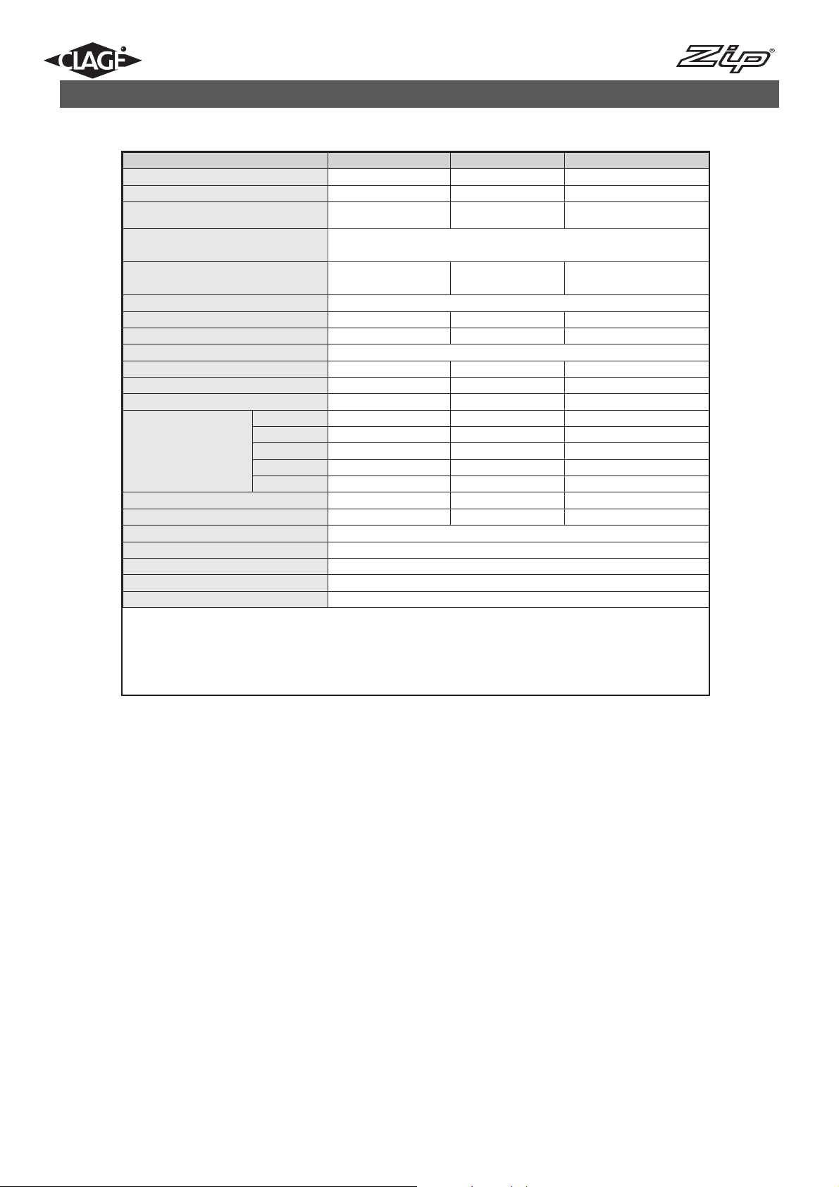
4. Technical specifications
Type MCX 3 MCX 4 MCX 6
Part no. 27300 27400 27600
Capacity (Liter) 0,2 0,2 0,2
Nominal pressure MPa (bar) 1 (10) 1 (10) 1 (10)
Heating system
Required water resistance at 15 °C
in cm
1100 800 800
Electric supply 1/N/PE ~ 220 V – 240 V
Nominal power rating 3,5 kW 4,4 kW 5,7 kW
Nominal current 15 A 19 A 25 A
Temperature choice 35 °C – 38 °C – 45 °C
Factory temperature setting 38 °C 38 °C 38 °C
Maximum inlet temperature 70 °C 70 °C 70 °C
Factory flow setting at 0.3MPa (3 bar) 2,0 l/min 2,5 l/min 3,3 l/min
2,0 l/min 25 K 31 K 41 K
Maximum temperature
increase at rated power
and a flow rate of......
2,5 l/min 20 K 25 K 33 K
3,0 l/min 17 K 21 K 27 K
1
3,5 l/min 14 K 18 K 23 K
4,0 l/min 12 K 16 K 20 K
Required l/min to switch on (l/min) 1,2 1,5 1,5
Required l/min to switch off
Min. required cable size
(l/min) 1,0 1,3 1,3
2)
Weight filled with water (kg) approx. 1,5
Dimensions H × W × D (mm) 135 × 186 × 87
Protection class acc. to VDE 1
Ingress protection according to VDE IP 25
1) Temperature rise (Kelvin) + cold-water temperature =
maximum hot-water temperature (°C) 70 °C
2) The cross sectional area of the connection cable must be in accordance with the power rating of the appliance and the specific requirements of AS/NZS 3000.
IES system
bare resistance element
See note 2)
5
Instructions for installer - 9120-15004 - MCX - 801053 - March 2013 v1.01
Page 6

Vented installation with
specialopenoutlettap
5. Typical installations
Electrical connection with mains
power cable
(shorten if necessary)
Cable entry approx. 553
Flow controller
MCX 3/4 : CSP 3
MCX 6 : CSP 6
Angle valve G 1/2“
Top edge of wash basin approx.. 850
Angle valve approx. 550
Axis wall bracket approx. 520
Dimensions in mm
6
Instructions for installer - 9120-15004 - MCX - 801053 - March 2013 v1.01
Page 7

Unvented installation
(closed outlet) with tap for
pressurised appliances
5. Typical installations
Electrical connection with mains
power cable
(shorten if necessary)
Flow controller
MCX 3/4 : CSP 3
MCX 6 : CSP 6
Angle valve G 1/2“
Top edge of wash basin approx.. 850
Angle valve approx. 550
Cable entry approx. 553
Axis wall bracket approx. 520
Dimensions in mm
7
Instructions for installer - 9120-15004 - MCX - 801053 - March 2013 v1.01
Page 8

6. Description of applicance
The Zip instantaneous water heaters are compact electronically controlled water heaters. It is intended to provide economical heating of
water for a wash basin when installed together with a sanitary water fitting. When the hot-water tap is opened, the heater switches itself
on automatically when the minimum water flow rate is exceeded and heats the water as it passes through the appliance.
There are 3 available temperature settings, 35ºC, 38ºC and 45ºC (Max).
For best performance, always fit the special flow controller included with the appliance. This controller is inserted into the outler at the
end of the tap and fits into any standard sleeve size M 22/24.
The maximum possible outlet temperature is determined by the temperature of the incoming water, the rate of flow and the heating
power of the appliance.
This appliance delivers water not exceeding 50ºC in accordance with AS3498.
7. Installation
The following regulations must be observed:
• Installation must comply with all statutory regulations, AS/NZS 3000, AS/NZS 3500, as well as those of the local electricity and water
supply companies.
• The specifications on the rating plate. The rating plate is located under the appliance‘s cover. See Section 10 on removing the cover.
• Technical specifications.
• These instructions must be read and fully understood before commencing the installation. If in doubt, or in need of further guidance
please ring Zip on 1800 638 633.
• Zip Instantaneous Hot Water heaters must be installed by a competent person familiar with electric instantaneous water heaters.
• Zip Instantaneous Hot Water heaters must be installed according to the specifi cation on the rating plate and the technical specifi cations.
• The appliance must be permanently connected to the electrical supply through an isolation switch as per AS/NZS 3000.
• To protect the appliance, a circuit breaker must be fi tted with a rating suitable for the nominal current of the appliance.
• The cross sectional area of the connection cable must be in accordance with the power rating of the appliance and the specifi c
requirements of AS/NZS 3000.
• Take care to protect the wiring from damage during installation and ensure that the wiring is not directly accessible after installation.
• Check that the power supply is switched off prior to electrical connection.
• This appliance must be earthed.
8
Instructions for installer - 9120-15004 - MCX - 801053 - March 2013 v1.01
Page 9

7. Installation
Installation site
• Appliance must only be installed in frost-free rooms. Never expose appliance to frost.
• The Appliance is designed for wall mounted installation and has to be installed with water connectors upwards.
• The appliance complies with protection class IP 25.
• In order to avoid thermal losses, the distance between the instantaneous water heater and the tapping point should be as small as
possible (< 0.5m).
• For maintenance work, a shut-off valve should be installed in the supply line. The appliance must be accessible for maintenance work.
• The hot water pipes must be thermally insulated.
• See Section 4 for the specific resistance of the water of each model at 15 °C. The specific resistance can be asked for with your water
supply company.
Installing the appliance
1. Secure the wall bracket to the wall with screws and wall plugs supplied (Fig. 1).
2. Place the appliance on the wall bracket and snap into position (Fig. 2).
NB: This appliance is intended for under sink installation with the water connections pointing vertically upwards.
See Section 11 if the appliance has to be removed from the wall bracket.
Fig. 1
Fig. 2
9
Instructions for installer - 9120-15004 - MCX - 801053 - March 2013 v1.01
Page 10

7. Installation
Pipe connection
1. The cold water inlet (blue) and hot water outlet (red) are marked on the rating plate. Connect the appropriate pipes from the tap to the
water inlet and outlet accordingly. Avoid exerting any mechanical pressure on the appliance by applying a spanner on the flats of the
inlet and outlet connections when tightening the pipe connectors (Fig.3).
2. Once the water connections have been made, check for any leaks and rectify as necessary.
3. In order to obtain an optimum water jet at low flow rates, always screw the jet regulator supplied with the unit onto the tap outlet.
This insert fits commercially available sleeves with an M22 or M24 thread.
4. To remove the water heater, insert a wide bladed screwdriver behind the unit from above and gently lever the unit out of the wall
bracket.
Fig. 3
Seal
Strainer
Cold Water
Connection
(inlet, G1/2”)
Seal
Hot Water
Connection
(outlet, G1/2”)
10
Instructions for installer - 9120-15004 - MCX - 801053 - March 2013 v1.01
Page 11

7. Installation
Electrical connection
Do not switch on the electric power at this time.
WARNING! To prevent damage to the appliance, the instantaneous water heater must be purged of air before using it for the first time.
Purging
Before connecting the electrical supply, open and close the hot water tap until the water runs smoothly and no more air emerges.
NOTE! Every time the appliance is drained (e.g. after work on the plumbing system, if there is a risk of frost or following repair work), the
heater must be purged in this way before reconnecting the power supply.
WARNING! This appliance must be earthed.
Installation must be carried out by a qualified electrician.
The electrical installation including earthing and cross bonding should comply with current Australian regulations and any Local Authority
requirements.
IMPORTANT:
The appliance must be installed according to the specification on the rating plate and the technical specifications. Ensure that the voltage
marked on the appliance matches the power supply.
The appliance must be permanently connected to the electrical supply.
To protect the appliance, a circuit breaker must be fitted with a rating suitable for the nomi nal current of the appliance.
The cross sectional area of the connection cable must be in accordance with the power rating of the appliance and the specific requirements of AS/NZS 3000.
Take care to protect the wiring from damage during installation and ensure that any uninsulated wiring is not directly accessible after
installation.
The cable must be adequately secured.
WARNING! Check that the power supply is switched off prior to electrical connection!
Fig. 4
Circuit diagram
1. Electronic regulator
2. Safety thermal cut-out
3. Heating element
NPE
(220 - 240V~) MCX 3..6
L
L
1
3
2
11
Instructions for installer - 9120-15004 - MCX - 801053 - March 2013 v1.01
Page 12

8. Commissioning
Commissioning
1. Close the circuit breaker to connect the electrical supply.
2. Check everything is working as it should and the water temperature is achieving the desired temperature. If not follow the guide below to
correct the temperature.
9. Flow rate adjustment
Adjustment of the flow rate is to be done by a Qualified Technician.
Adjustments are done by turning the adjusting screw located under the appliance’s cover.
Removing the cover
The rating plate and the adjusting screw for the flow rate is located under the cover.
1. Push the cover on the corrugated side towards the wall bracket.
2. At the rear corners press the cover down (A) until the front edge lifts (B).
3. Remove the cover by pulling forward and upwards.
A
A
B
Replacing the cover
To replace the cover, reverse the process as described in the process for removing the cover above.
1. Push the cover flat towards the wall bracket under the edges of the water connections.
2. Press down the front edge of the cover and push it forward again at the rear edge until it fits.
12
Instructions for installer - 9120-15004 - MCX - 801053 - March 2013 v1.01
Page 13

9. Flow rate adjustment
Adjustment of the flow rate is to be done by a Qualified Technician.
Decreasing the flow rate:
Turning the adjusting screw clockwise decreases the flow rate, thus making a higher outlet temperature possible.
Increasing the flow rate:
Turning the adjusting screw counter-clockwise increases the flow rate, thus reducing the possible outlet temperature.
Tem pe ra ture
Direction Flow
in crease (+) /
decrease (-)
–+
+–
10. Removing the appliance from the wall bracket
To remove the appliance from the wall bracket:
1. Insert a flat head screwdriver all the way into the lock.
2. Gently angle the screwdriver upwards by approximately 10° as shown in the image below.
3. Pull the appliance forwards by approximately 15° as shown in the image below.
4. Carefully pull the appliance upwards to complete the removal process.
NB: See Section 8 on reinstalling the appliance.
13
Instructions for installer - 9120-15004 - MCX - 801053 - March 2013 v1.01
Page 14

11. Maintenance
• The appliance and fittings should only be cleaned with a damp cloth. Do not use abrasive or chlorine-based cleaning agents or solvents.
• Keep the control panel area dry.
• Clean the jet regulator regularly and replace as necessary.
• Dirt and scale deposited in the pi
flow. In such cases, have the appliance inspected by a qualified technician and, if necessary, have the filter in the cold-water inlet
cleaned.
pes and appliance will affect its function. Typical indications of this are a reduced flow rate or noisy
12. Fault finding
Repairs should only be carried out by qualifi ed tradespersons familiar with electric instantaneous water heaters.
All service work should be performed by an authorized Zip service technician – for details of the full range of services available call Zip
Service on 1800 460 222.
When calling for service, please always specify the appliance model and serial number.
The following table will be helpful in determining the causes of some common problems and their solutions.
Problem Cause Solution
Circuit breaker tripped Reset circuit breaker
Cold water at outlet
Water fl ow is not suffi cient Increase the water fl ow to the appliance
Flow controller not fi tted
Slow water fl ow rate at outlet
No water at outlet Water supply is turned off Turn on water supply
Appliance switches itself on and
off
Hot water temperature not stable
during use
Hot water temperature too low
and/or one LED fl ashes slowly
One LED fl ashes fast and water
remains cold
All LEDs fl ashing fast and water is
warm
All LEDs fl ashing fast and water
is cold
LEDs turn off shortly after key
press
Water pressure not suffi cient Contact Zip Service
Dirt in the pipes Clean fi lter, if problem persist, contact Zip Service
Varying water pressure / fl ow rate is too low
Supply voltage varies / Water connections
reversed
Flow rate is too high
Voltage supply is too low Contact Zip Service
Faulty heating element Contact Zip Service
Defective temperature sensor Contact Zip Service
Faulty heating element Contact Zip Service
Defective control panel Contact Zip Service
Defective power unit Contact Zip Service
Keylock function is active Deactivate Keylock, see instructions on page 8
Fit the correct fl ow controller (see Section 6) or
contact Zip Service
Clean fi lter, increase the water fl ow to the appli-
ance. If problem persist, contact Zip Service
Contact Zip Service
Adjust the fl ow either at the tap, the valve or the
fl ow adjustment screw. Zip Service should be
contacted to adjust the fl ow adjustment screw
14
Instructions for installer - 9120-15004 - MCX - 801053 - March 2013 v1.01
Page 15

13. Notes
15
Instructions for installer - 9120-15004 - MCX - 801053 - March 2013 v1.01
Page 16

Head Office
Zip Heaters (Aust) Pty. Ltd.
ABN: 46 000 578 727
67 Allingham Street
Condell Park NSW 2200
Postal: Locked Bag 80
Bankstown 1885 Australia
Website: www.zipheaters.com
Facsimile: (02) 9796 3858
Telephone: (02) 9796 3100
Free Call: 1 800 638 633
As Zip policy is one of continuous
product improvement, changes
to specifications may be made
without prior notice. Images in this
booklet have been modified and
may not be true representations of
the finished goods.
12. Quick reference guide
Instructions for installer - 9120-15004 - MCX - 801053 - March 2013 v1.01
 Loading...