

Page 1

Wireless LAN Device Series
Wifi N module
WPL-2N00
User’s Manual
Version. 1 (2010.8.26)
1
Page 2

Notice
FCC Warning
Changes or modifications to this unit not expressly approved by the party responsible for
compliance could void the user authority to operate the equipment.
This device complies with Part 15 of the FCC Rules. Operation is subject to the following
two conditions: (1) This device may not cause harmful interference, and (2) this devic e
must accept any interference received, including interference that may cause undesired
operation.
The user’s manual or instruction manual for an intentional or unintentional radiator shall
caution the user that changes or modifications not expressly approved by the party
responsible for compliance could void the user’s authority to operate the equipment.
FCC Statement
This equipment has been tested and found to comply with the limits for a Class B digital
device, pursuant to Part 15 of the FCC Rules. These limits are designed to provide
reasonable protection against harmful interference in a residential installation. This
equipment generates uses and can radiate radio frequency energy and, if not installed and
used in accordance with the instructions, may cause harmful interference to radio
communications.
However, there is no guarantee that interference will not occur in a particular installation. If
this equipment does cause harmful interference to radio or television reception, which can
be determined by turning the equipment off and on, the user is encouraged to try to correct
the interference by one or more of the following measures:
Reorient or relocate the receiving antenna.
Increase the separation between the equipment and receiver.
Connect the equipment into an outlet on a circuit different from that to which the receiver
is connected.
Consult the dealer or an experienced radio/TV technician for help.
FCC RF Radiation Exposure Statement
This equipment complies with FCC radiation exposure limits set forth for an uncontrolled
environment. This equipment should be installed and operated with minimum distance
20cm between the radiator & your body. For product available in the USA/Canada market,
only channel 1~11 can be operated. Selection of other channels is not possible. The
antenna(s) used for this transmitter must not be co-located or operating in conjunction with
2
Page 3

any other antenna or transmitter. Shielded interface cables must be used in order to comply
with emission limits.
CE Statement
ZINWELL, hereby declares that this device is in compliance with the essential requirement
and other relevant provisions of the R&TTE Directive 1999/5/EC.
This device will be sold in the following EEA countries:Austria, Italy, Belgium, Liechtenstein,
Denmark, Luxembourg, Finland, Netherlands, France, Norway, Germany, Portugal, Greece,
Spain, Iceland, Sweden, Ireland, United Kingdom, Cyprus, Czech Republic, Estonia,
Hungary, Latvia, Lithuania, Malta, Slovakia, Poland, Slovenia, Bulgaria, Romania.
3
Page 4

Preface
This guide is for the experienced user who installs and manages the Zinwell WiFi N
MODULE product hereafter referred to as the “device”. To use this guide, you should have
experience working with the TCP/IP configuration and be familiar with the concepts and
terminology of wireless local area networks.
4
Page 5

TABLE OF CONTENTS
NOTICE ...............................................................................................................................................................2
PREFACE............................................................................................................................................................4
CH 1. WIFI N MODULE INSTALLATION...........................................................................................................7
CONNECTORS ................................................................................................................................................. 7
CH 2. FIRST TIME CONFIGURATION...............................................................................................................9
BEFORE START TO CONFIGURE ........................................................................................................................ 9
KNOWING THE NETWORK APPLICATION ............................................................................................................. 9
CH 3. DETAIL CONFIGURATION..................................................................................................................... 11
SETUP WIZARD...............................................................................................................................................11
OPERATION MODE......................................................................................................................................... 12
TCP/IP SETTINGS......................................................................................................................................... 13
Configuring LAN Interface...................................................................................13
WIRELESS SETTINGS ..................................................................................................................................... 14
AP mode..............................................................................................................14
Basic....................................................................................................................14
Advanced ............................................................................................................17
Security ...............................................................................................................19
WPS....................................................................................................................22
Site Survey..........................................................................................................24
Repeater Mode....................................................................................................25
Station List...........................................................................................................26
Client mode .........................................................................................................26
Profile..................................................................................................................26
Link Status...........................................................................................................27
Site Survey..........................................................................................................28
Statistics..............................................................................................................29
Advanced ............................................................................................................29
QoS.....................................................................................................................30
11n Configurations...............................................................................................30
WPS....................................................................................................................31
MANAGEMENT ............................................................................................................................................... 32
Status ..................................................................................................................32
Statistic................................................................................................................33
System Management...........................................................................................33
Upgrade Firmware...............................................................................................33
Save/Reload Settings..........................................................................................34
5
Page 6

System Command...............................................................................................34
System Log .........................................................................................................34
CHANNEL NUMBER ........................................................................................................................................35
SPECIFICATION ...............................................................................................................................................36
6
Page 7
Ch 1. WiFi N MODULE Installation
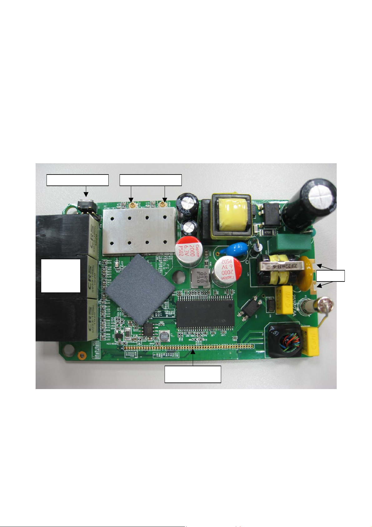
Connectors
In the front of the module:
Ethernet
Port X3
Reset button
Wi-Fi Antenna X2
AC
Reset Button: Press Reset button to revert it to factory default.
Wi-Fi Antenna X2: connect to Wi-Fi antenna.
Ethernet port X3: connect to Ethernet for LAN connection.
AC: connect AC, 250V/2.5A Max.
PIN: connect to PLC module.
PIN
7
Page 8
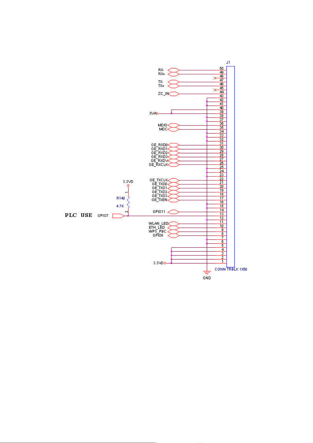
PIN definition:
8
Page 9
Ch 2. First Time Configuration
Before Start to Configure
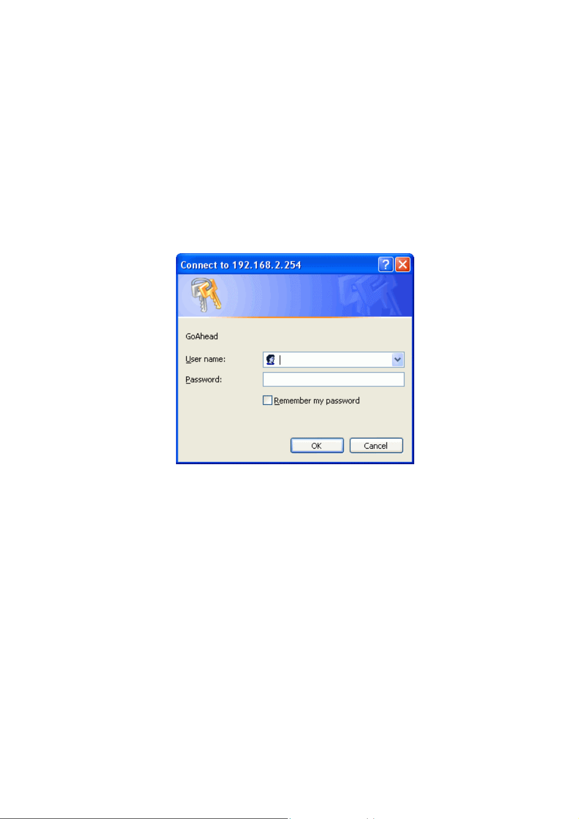
The configuration of this device is through web-browser. To access the configuration
interfaces, make sure you are using a computer connected to the same network as the
device. The default IP address of the device is 192.168.2.254, and the subnet-mask is
255.255.255.0. For the first time configuration, please login with username: root and
password: root.
Please note that the DHCP server inside the device is default to up and running. Do not
have multiple DHCP servers in your network environment, otherwise it will cause
abnormal situation.
Knowing the Network Application
The device can act as the following roles, and it supports WDS (Wireless Distribution
System) function.
Access Point
WDS mode
AP Client / Bridge mode
The device provides 3 different operation modes and the wireless radio of device can act
as AP/Client/WDS. The operation mode is about the communication mechanism
between the wired Ethernet NIC and wireless NIC. Following are the types of operation
mode.
9
Page 10
Bridge
The wireless radio of the device acts as the following roles.
AP (Access Point)
The wireless radio of device serves as communications “hub” for wireless clients and
provides a connection to a wired LAN.
Client mode
This mode enables the establishment of connection with the other AP using
infrastructure/Ad-hoc networking types. With bridge operation mode, you can directly
connect one of the wired Ethernet port to your PC and the device becomes a wireless
adapter. And with WISP operati on mode, you can connect one of the wired Ethernet port
to a hub/switch and all the PCs connecting with hub/switch can share the same public IP
address from your ISP.
WDS (Wireless Distribution System)
This mode combines up to 8 AP to a single wireless network; the device forwards the
packets to another AP with WDS function. When this mode is selected, all the wireless
clients can’t survey and connect to the device. The device only allows the WDS
connection.
AP + WDS
This mode combines WDS plus AP modes, and it not only allows WDS connections but
also the wireless clients can survey and associate to the device.
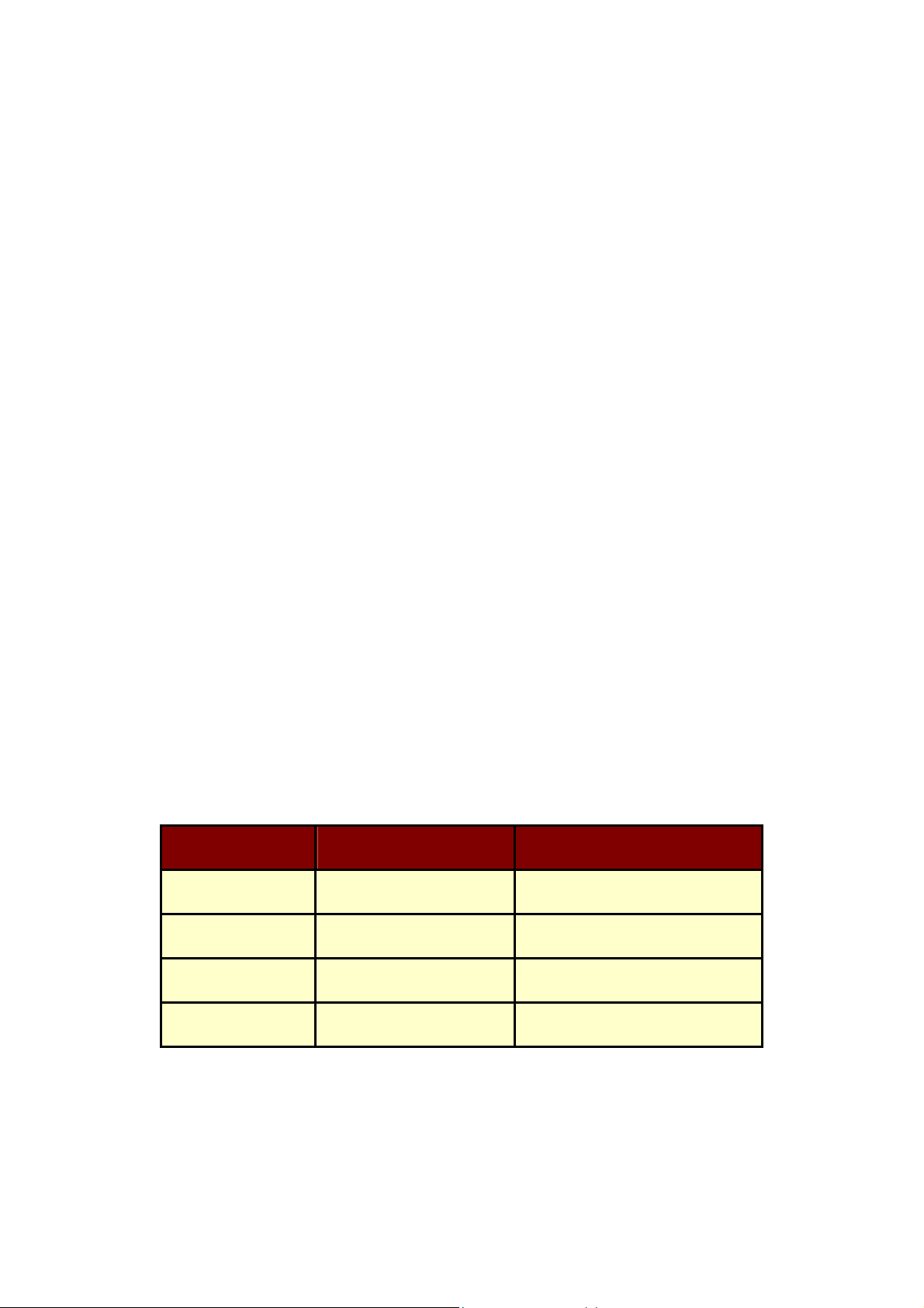
The following table shows the supporting Wi-Fi role/function for each mode.
Role Bridge mode AP Client(Bridge) Mode
Wi-Fi AP
WDS
Client
AP+WDS
Yes (Repeater) Yes
Yes No
Yes No
Yes No
10
Page 11
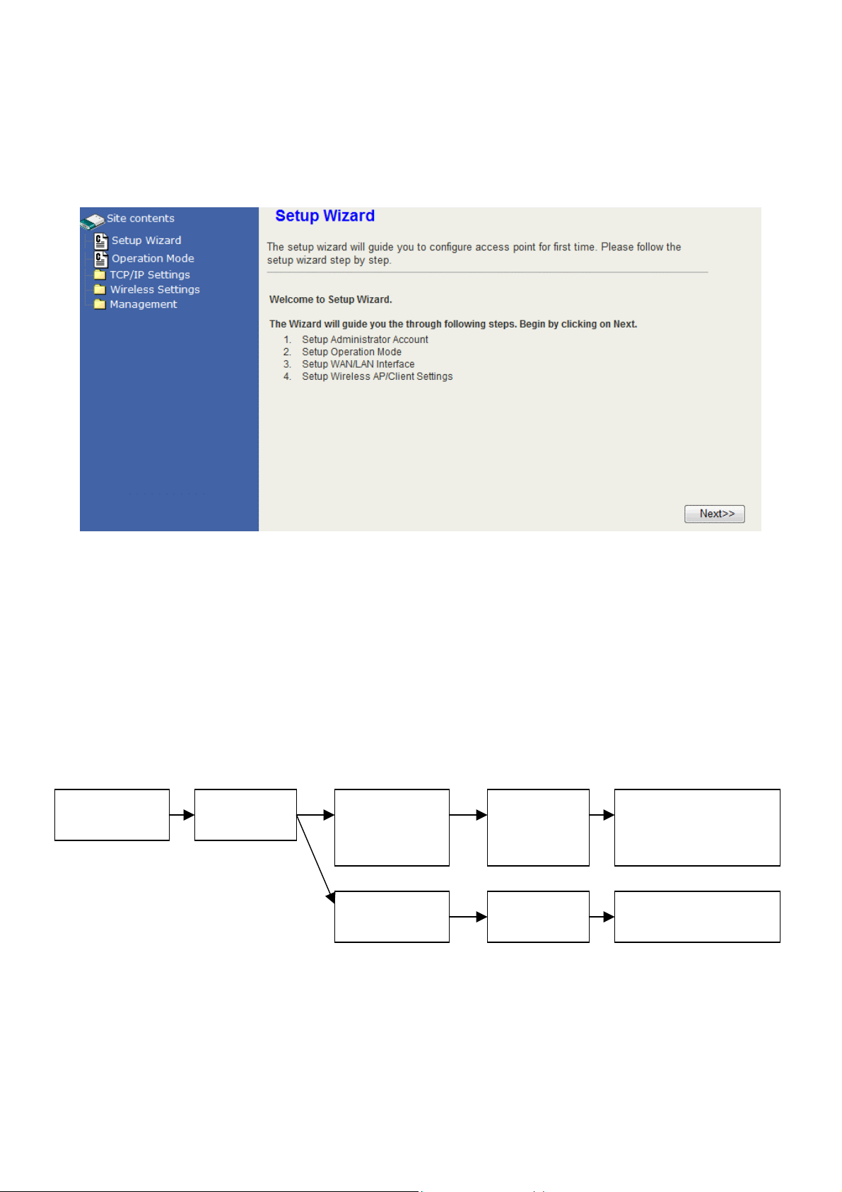
Ch 3. Det ail Configuration
Setup Wizard
The setup Wizard can help you to setup the device with minimum setting. Open the page
in the left panel and click “Next>>” button in the welcome page. In the first page, enter the
new account name and password for login this web page configuration in the future. In the
next page, choose the device to be Bridge mode or AP Client (Bridge) mode. Choosing
each mode will have the respect setting pages like the figure below. Please refer to the
pages in the next section for the explanation of each setting. In the final step of setting, click
“Finish” button and the device will reboot to apply the settings.
Administrator
Account
Operation
Page
Bridge Mode:
LAN Settings
AP Client:
LAN Settings
Basic
Wireless
Settings
Site Survey Profile
Wireless
Security/Encryption
Settings
11
Page 12
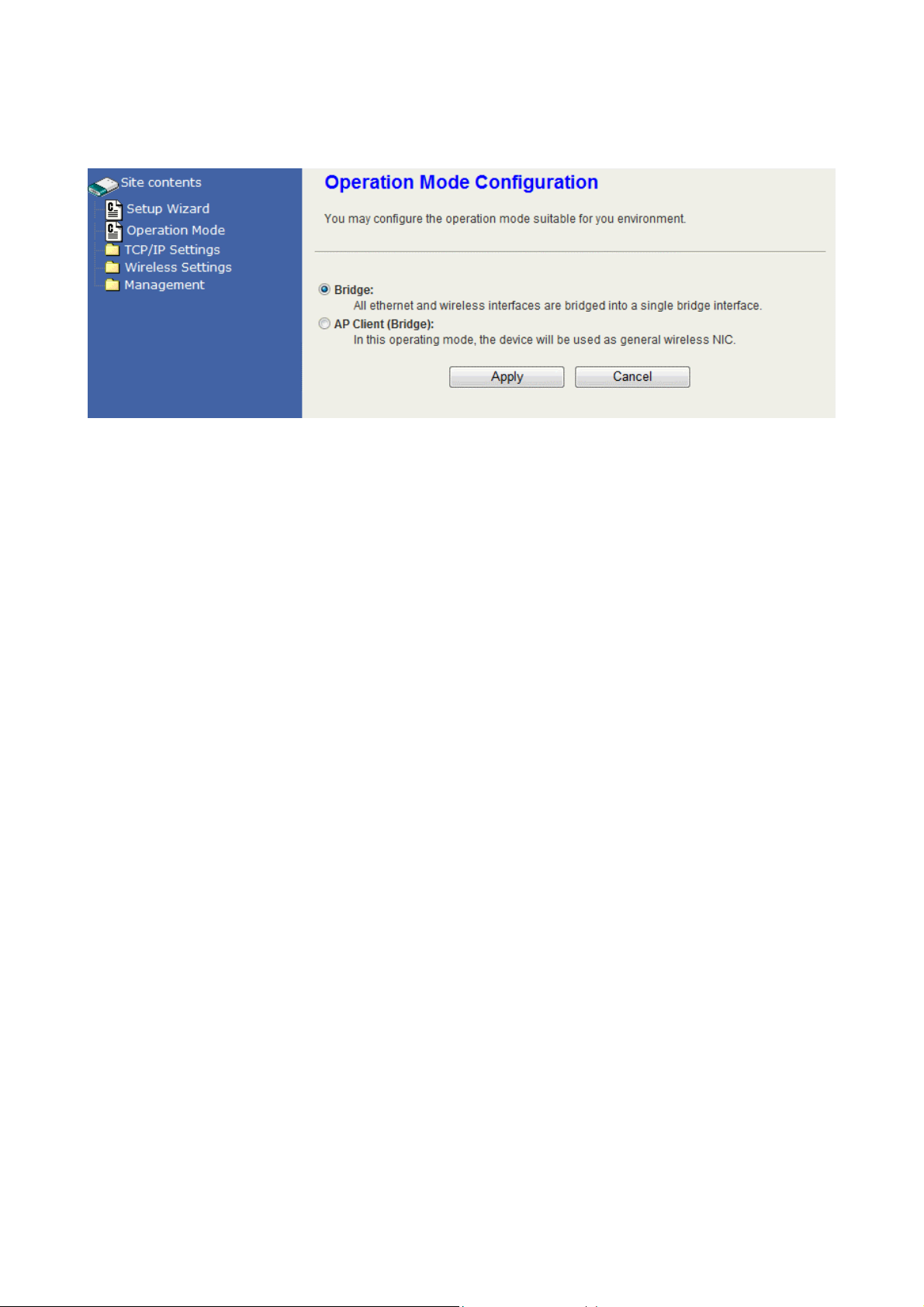
Operation Mode
This device supports 2 modes for the IP network. Click the radio button to select one
among the modes.
Bridge: This device is the Access Point with Ethernet switch mode.
AP Client (Bridge): This device simulates the function of Wireless LAN Card (Station)
with Ethernet switch mode. It will connect to an Access Point for wireless
connection.
12
Page 13
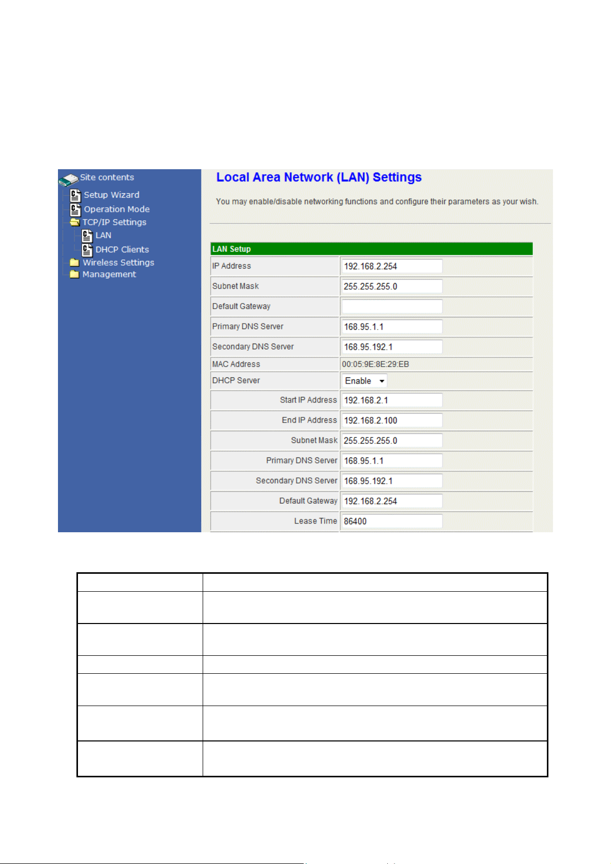
TCP/IP Settings
Configuring LAN Interface
Item
IP Address
Subnet Mask
MAC Address
DHCP Type
Start IP Address
End IP Address
Description
This is the IP Address for this device. You can login this IP
Address via LAN/WLAN, and you can change it if you want to.
This is the subnet mask for the LAN. The default value is
“255.255.255.0”.
The MAC Address of LAN is showed in this field.
You can select to enable DHCP server. When enabling the
DHCP server, you must setup the information below.
This is the first IP Address of the IP pool which the server
assigns the IP Address from.
This is the last IP Address of the IP pool.
13
Page 14
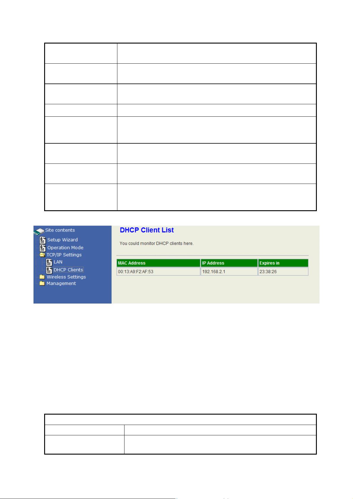
Subnet mask
This is the subnet mask of this domain. The default value is
“255.255.255.0”.
Primary DNS
Server
Secondary DNS
Server
Default Gateway
Lease Time
Statically
Assigned
802.1d Spanning
Tree:
LLTD
This is the primary DNS server for the LAN PCs.
This is the second DNS server for the LAN PCs.
This is the default gateway for the LAN PCs.
This is the DHCP lease time. When it is short, the IP
release/renew of the LAN will be faster but the network
congestion will be more.
You can manually assign the IP Address to the certain PCs.
Enter the MAC Address and IP Address in the table.
Enable this function to prevent the broadcast storm in the
LAN.
Enable this function to support LLTD (Link Layer Topology
Discovery) for Windows Vista. It shows the status of
connection in the Windows Vista.
Wireless Settings
AP mode
Basic
Basic Settings
Item
Radio On/Off
Description
Click the “RADIO OFF” button to turn off the radio. Click it
again to turn on the radio.
14
Page 15

Network Mode
The available options are “11b/g mixed mode”, “11b only”,
“11g only” and “11b/g/n mixed mode”. We recommend
selecting the default vale “11b/g/n mixed mode”.
Network Name (SSID)
Multiple SSID 1-3
Broadcast Network
Name (SSID)
AP Isolation
MBSSID AP Isolation
The SSID, which is also called ESSID is a unique identifier
that wireless networking devices use in order to establish
and maintain wireless connectivity. Multiple access
point/bridges on a network or sub-network can use the
same SSID. SSIDs are case sensitive and can contain up
to 32 alphanumeric characters.
This device supports multiple SSID. Input the multiple SSID
1, 2, 3 in the field to enable the function. With the field of
Network Name (SSID), the device supports maximum 4
SSIDs.
Disable this function to hide SSID. With hidden SSID, the
AP can’t be scanned and the wireless client must input
SSID manually to associate this AP.
The device supports isolation function. If you are building a
public Wireless Network, enable this function can provide
better security. The device will block packets between
wireless clients (relay). All the wireless clients connected to
the device can’t see each other.
The device supports multi-SSID. You can decide whether
the clients associated to different SSID on the device can
see each other. Enable the option to block it. The Default
value is “Disable”.
BSSID
Frequency (Channel)
The BSSID is displayed in this field.
Click the drop down box to select the radio channel. Select
the unused channel to prevent the radio overlapping. If you
are not sure which channel is used, select “AutoSelect” to
let the device to detect and select the available channel.
Wireless Distribution System (WDS)
Item
WDS Mode
Description
This device supports “WDS Mode only” and “AP+WDS
Mode”. When selecting WDS mode only, this device
provides WDS connection only and doesn’t provide radio to
the WLAN stations (clients). To provide both AP and WDS
connections, select “AP + WDS Mode”.
AP MAC Address
This device supports 4 WDS devices. Enter the MAC
Address in the field to connect.
15
Page 16

HT Physical Mode
Item
Operating Mode
Channel Bandwidth
Guard Interval
MCS
Description
Default: Mixed (Mixed, Green Field).
Mixed mode: In this mode the device transmits the packets
with preamble compatible legacy (802.11g), so they can be
decoded by legacy devices. The device receives and
decodes both Mixed Mode packets and legacy packets.
Green Field mode: the device transmits HT packets
without legacy compatible part. But the device receives and
decodes both Green Field and legacy packets.
This option only works when selecting Band mode in
802.11b/g/n Mixed m ode. Click the radio button to choose
between 20 MHz or 20/40MHz. This option affects the Phy
data rate of radio. Please refer to the table below
The 11n device inserts the Guard Interval into the signal.
You can choose the interval between “Long” and “Auto”.
This option affects the Phy data rate of radio. Please refer
to the table below.
It is Modulation Coding Scheme. The available options are
“Auto, 0, 1, …, 32”. It changes the modulation of this device
and effect the maximum Phy data rate. We recommend
“Auto” setting. For the details, please refer to the table
below.
Extension Channel
The “20/40” bandwidth mode uses 5 channels. For
example, selecting channel 7 and you can select 3 or 11 for
extension channel. Choose the unused channel for the
extension channel.
Aggregation MSDU
(A-MSDU)
The multiple HT packets can be transmitted with single
ACK reply packet. Enable it to apply this function and
reduce the network congestion.
Auto Block ACK
It is another aggregation technique which prevents sending
ACK in the communication to increase the throughput. If
this option is enabled, the device will activate this function
when transmitting massive data.
Decline BA Request
Enable this option to decline the Block ACK request
addressed by the other devices.
The table below shows the relationship among Phy data rate, Bandwidth and Guard
Interval.
Data Rate
Mbps
MCS
Bandwidth = 20MHz Bandwidth = 40MHz
Short Guard
Interval
Long Guard
Interval
Short Guard
Interval
Long Guard
Interval
0 (1S) 7.2 6.5 15 13.5
16
Page 17

1 14.4 13 30 27
2 21.7 19.5 45 40.5
3 28.9 26 60 54
4 43.3 39 90 81
5 57.8 52 120 108
6 65 58.5 135 121.5
7 72.2 65 150 135
8 (2S) 14.4 13 30 27
9 28.9 26 60 54
10 43.3 39 90 81
11 57.8 52 120 108
12 86.7 78 180 162
13 115.6 104 240 216
14 130 117 270 243
15 144.4 130 300 270
32 Not Supported Not Supported 6.7 6
MCS: Modulation Coding Scheme
MCS=0~7 (1S, One Tx Stream)
MCS=8~15 (2S, Two Tx S tream)
MCS 32: BPSK
Advanced
Advanced Wireless
Item
BG Protection Mode
Beacon Interval
Description
Default: Auto. You can select the other options including On
and Off. The B/G protection technology is CTS-To-Self. It
will try to reserve the throughput for 11g clients from 11b
clients connecting to the device as AP mode.
Beacons are the packets sending by Access point to
synchronize the wireless network. The beacon interval is
Data Beacon Rate
(DTIM)
the time interval between beacons sending by this unit in
AP or AP+WDS mode. The default and recommended
beacon interval is 100 milliseconds.
This is the Delivery Traffic Indication Map. It is used to alert
the clients that multicast and broadcast packets buffered at
17
Page 18
the AP will be transmitted immediately after the
transmission of this beacon frame. You can change the
value from 1 to 255. The AP will check the buffered data
according to this value. For example, selecting “1” means
to check the buffered data at every beacon.
Fragment Threshold
RTS Threshold
TX Power
Short Preamble
The fragmentation threshold determines the size at which
packets are fragmented (sent as several pieces instead of
as one block). Use a low setting in areas where
communication is poor or where there is a great deal of
radio interference. This function will help you to improve the
network performance.
The RTS threshold determines the packet size at which the
radio issues a request to send (RTS) before sending the
packet. A low RTS Threshold setting can be useful in areas
where many client devices are associating with the device,
or in areas where the clients are far apart and can detect
only the device and not each other. You can enter a setting
ranging from 0 to 2347 bytes.
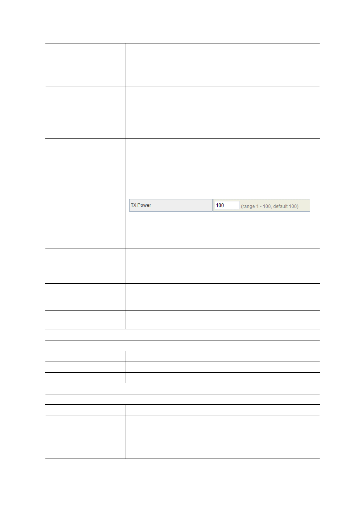
The default TX power is 100%. In case of shortening the
distance and the coverage of the wireless network, input a
smaller value to reduce the radio transmission power. For
example, input 80 to apply 80% Tx power.
Default: Disable. It is a performance parameter for 802.11
b/g mode and not supported by some of very early stage of
802.11b station cards. If there is no such kind of stations
associated to this AP, you can enable this function.
Short Slot
Tx Burst
Wi-Fi Multimedia
Item
WMM Capable
WMM Parameter
Multicast-to-Unicast Converter
Item
Multicast-to-Unicast
For a WLAN network with 802.11g/n devices, the time slot
can be set short to increase the throughput. Disable this
option for the backward compatibility with 802.11b device.
The device will try to send a serial of packages with single
ACK reply from the clients. Enable this function to apply it.
Description
Choose “Enable” to enable WMM function.
Click the button to edit the WMM parameter.
Description
Enable/Disable to enable this function. Multicast Ethernet
package will be converted to Unicast package. If disable
this function, the Multicast package will be forwarded in
Broadcast method which takes more bandwidth in the
18
Page 19

network.
Security
Wireless Security/Encryption Settings
Select SSID
Item
SSID choice
Description
Choose the ESSID to configure the security setting.
Wireless Security/Encryption Settings
Item
Security Mode
Description
Disable, OPEN, SHARED, WEPAUTO, WPA, WPA-PSK,
WPA2, WPA2-PSK, WPA/WPA2 PSK, WPA/WPA2,
802.1X.
The available options are showed according to the numbers of the BSSID in the
Basic Setting. Each SSID can setup different encryption type. For example, set up 4
BSSID and 4 sets of security shows on this page:
Security Mode: Choose one as the wireless authentication among the following
types: Open, Shared, WEP Auto, WPA, WPA-PSK, WPA2, WPA2-PSK,
WPA/WPA2-PSK, WPA/WPA2, and 802.1 X.
Encryption Type: Select one for the encryption type. The options vary
depending on the Authentication mode. The corresponding options shows
below.
Authentication Encryption
Open/Shared/WEP
Auto
WPA/WPA2-PSK
(Pre-Shared Key)
WPA/WPA2
Enterprise
WEP Encryption Setting
Wired Equivalent Privacy (WEP) is implemented in this device to prevent
unauthorized access to your wireless network. The WEP setting must be as same as
Key option
type
WEP Default Key ID, Key content of Key
1/2/3/4
TKIP, AES,
TKIP/AES
TKIP, AES,
TKIP/AES
Pass Phrase (8-32 bytes), Key
Renewal Interval
Radius Server
Network/Address/Port/Key/Session
timeout
19
Page 20

each client in your wireless network.
Authentication Type: Open, Shared and Auto. When choose “Open” or “Shared”,
all of the clients must select the same authentication to associate this AP. If
select “WEP Auto”, the clients don’t have to use the same “Open” or “Shared”
authentication. They can choose any one to authenticate.
Default Key ID: Select whether the Key ID as the default Key.
Key 1/2/3/4: Select “ASCII” or “Hex” and then type the key in the text field.
64-bit WEP Encryption:64-bit WEP keys are as same as the encryption
method of 40-bit WEP. When input 10 hexadecimal digits (0-9, a-f or A-F) or
5 ACSII chars as the key, it is using 64-bit WEP encryption.
128-bit WEP Encryption:128-bit WEP keys are as same as the encryption
method of 104-bit WEP. When input 26 hexadecimal digits (0-9, a-f or A-F)
or 10 ACSII chars, it is using 128-bit WEP encryption.
WP A Authentication Mode
This device supports six WPA modes including WPA-PSK (Pre-Shared Key), WPA,
WPA2-PSK, WPA2 and additional WPA/WPA2 PSK and WPA/WPA2 mixed mode.
For individual and residential user, it is recommended to select WPA-PSK or
WPA2-PSK to encrypt the link without additional RADIUS server. This mode requires
only an access point and client station that supports WPA-PSK. For WPA/WPA2,
authentication is achieved via WPA RADIUS Server. You need a RADIUS or other
authentication server on the network.
WPA/WPA2-PSK:
Pass Phrase:
Option: Pass Phrase (8-32bytes). This mode requires only an access point
and client station that supports WPA-PSK. The WPA-PSK settings include
Key Format, Length and Value. They must be as same as each wireless client
in your wireless network. When Key format is Passphrase, the key value
should have 8-63 ACSII chars.
Key Renewal Interval:
The WPA Algorithm will regroup the key for a period. The default value is
3600 seconds and you can adjust the time interval.
WPA/WPA2:
When selecting WPA/WPA2, you have to add user accounts and the target device
to the RADIUS Server. In the device, you need to specify the Server Network,
Server address, Server Port and Server Key of the target RADIUS server.
WPA Algorithms: TKIP, AES, TKIP/AES. Select the encryption type.
20
Page 21
When selecting TKIP/AES, the client can use whether TKIP or AES for
the authentication.
Pre-Authentication Support option: This option only appears when
selecting WPA2 or WPA/WPA2 as the authentication mode. Enable it to
use this function.
Radius Server setting:
IP Address: Input the IP Address of the Radius server.
Port: Input the port of the Radius server. The default port is 1812.
Shared Secret: Input the Authentication Key .
Session Timeout: Input the maximum idle time for this connection.
Ethernet
AP
Wireless Station
RADIUS Server
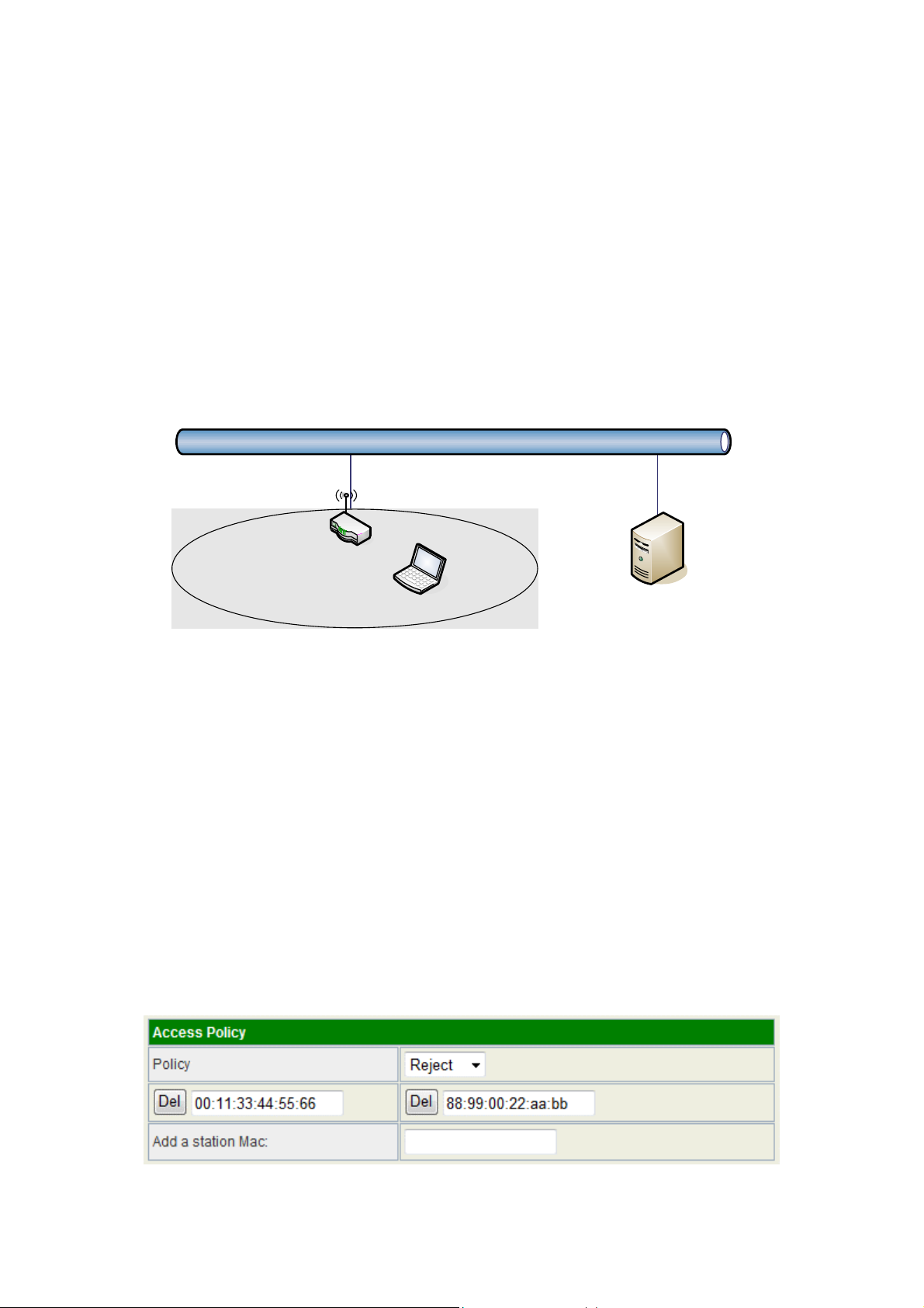
Access Policy
For each SSID, the Access Policy can be selected and setup. The policy includes
“Reject” and “Allow”. The Reject policy rejects the station according to the MAC table
in the policy configuration, and let the other stations to connect. The allow policy
performs reversely.
Add a station MAC: Key in station MAC Address in the text field. The valid format of
the MAC Address is “00:11:22:33:44:55”. The station MAC Address can be found on
the label or configure utility of the WLAN card. For deleting one record in the table,
click the “Del” button of the record. The maximum number of record on the table is
32.
21
Page 22

WPS
This function helps to establish the Wi-Fi security. For AP mode, it can be setup one WPS
method including PIN (Personal Identification Number) and PBC (Push Button
Certification).
To begin the WPS progress, the WLAN security must be setup first. Please setup one
among WPAPSK, WPA2PSK, WPA/WPA2PSK and then apply WPS setting.
PIN: query the PIN code in the utility of WLAN client, and then enter it in the PIN field. The
Wi-Fi link between the WLAN client and the device should be encrypted.
PBC: Select PBC, and then you can begin the PBC process. Press the PBC button in the
front panel can also trigger this process. Press or click the PBC button on the WLAN client
to finish the communication. You can press the PBC button on the WLAN client first and
then click the PBC button on this device to establish the encryption.
The options and the information fields are showed below.
WPS Config
Item
WMM Capable
WPS Summary
Item
WPS Current Status
WPS Configured
WPS SSID
WPS Auth Mode
WPS Encryp Type
AP PIN
Description
Select to enable this function.
Description
It shows the current status of the WPS process.
It indicated whether the WPS is configured.
It is the first SSID of the device.
It indicates the authenticate mode of this device. It can be
configured in the wireless security page.
It indicates the encryption method of this device. Like WPS
authentication mode, it can be configured in the wireless
security page.
It shows the current PIN number of this device.
Reset OOB button
WPS Progress
Item
Press this button to reset the WPS of this device. The AP
PIN number will be changed.
Description
22
Page 23
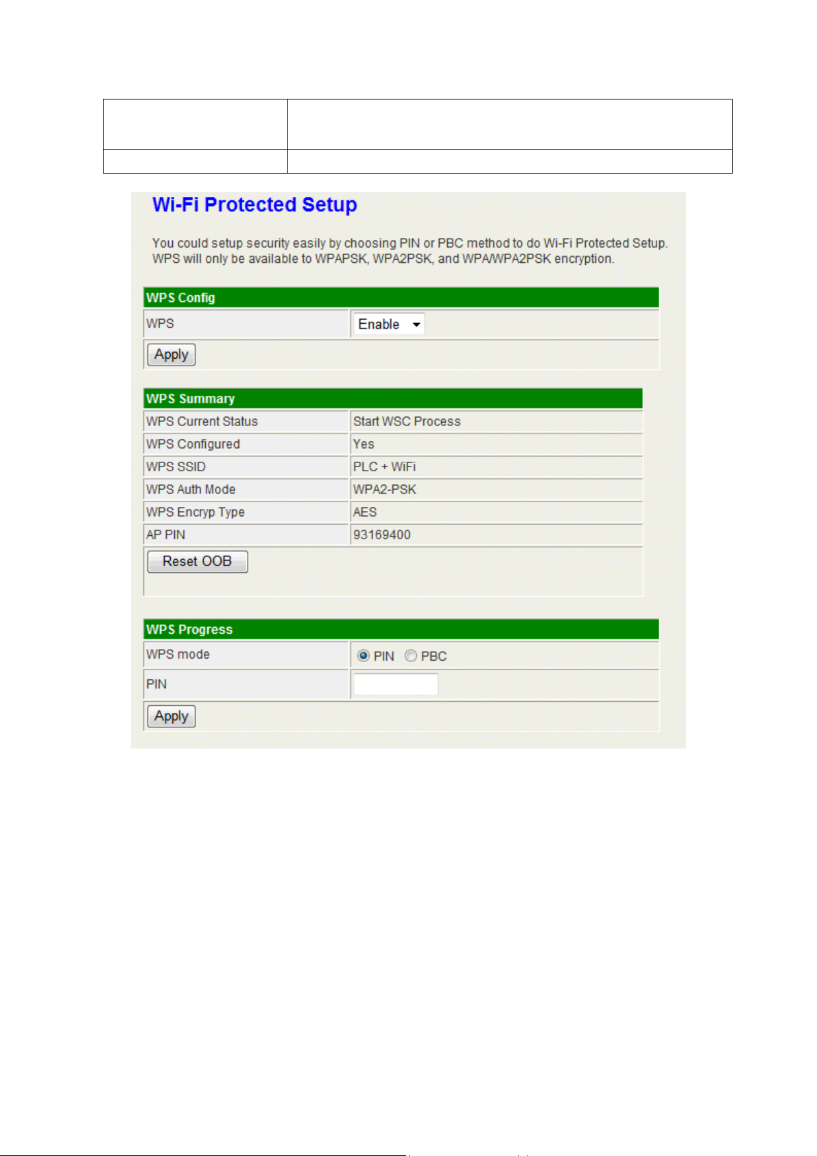
WPS mode
PIN
Choose to use PIN (Personal Identification Number) or
PBC (Push Button Certification).
Input the 8-digit PIN of client.
23
Page 24
Site Survey
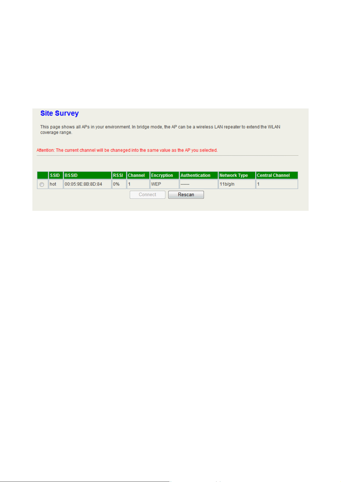
In this page, you can scan the AP signals in the air. You can setup the device to use a
clear channel according to the channel list, or connect to one of them to enable the
“Repeater” function.
24
Page 25
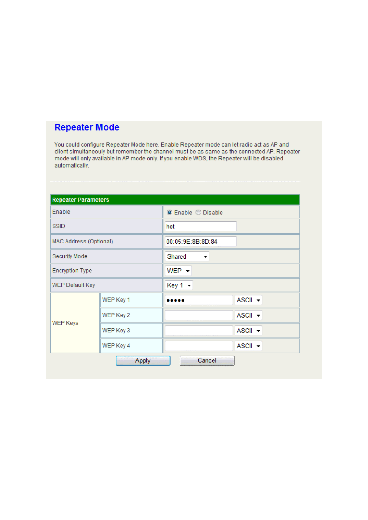
Repeater Mode
This device can connect to the remote AP and forward its signal to the other wireless
client/station. Enable this function and input the necessary setting to connect the remote AP,
or connect it in the site survey page to apply this function.
25
Page 26
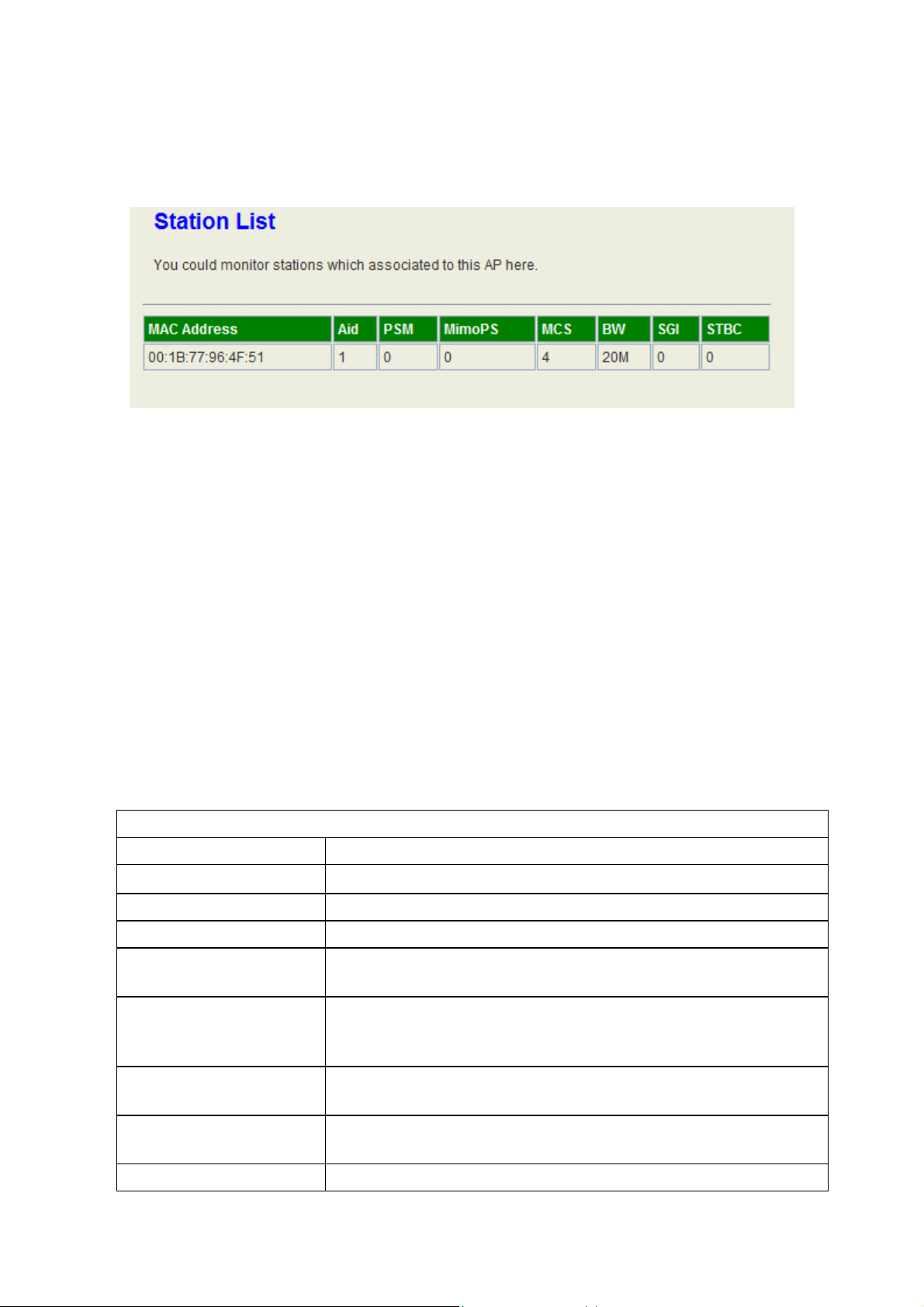
Station List
In the Station list, the information of associated clients is displayed.
Client mode
Profile
In the first page, you can see the profile list to show the information including Profile
name, SSID, Channel, Authentication, Encryption and Network Type. Use four buttons to
manage the profile list. The “Add” button is to add a new profile. The “Delete” button is to
delete the selected profile. The “Edit” button is to edit the selected profile. The “Activate”
button is to enable the selected button, so this device will associate to the AP according to
the profile.
System Configuration
Item
Profile Name
SSID
Network Type
Channel
11B Preamble Type
Power Saving Mode
Description
Enter your profile name.
Enter the SSID of the AP or Ad Hoc network.
Choose one between “802.11Ad Hoc” and Infrastructure.
This option shows only for the Ad Hoc network. Select one
for it.
In the Ad Hoc network, choose “Long” for the compatibility
of the some old 802.11b station cards, or “Auto” for setup
this option automatically.
For the Infrastructure network, this device can be setup to
CAM (Constantly Awake Mode) or Power Saving Mode.
RTS Threshold
Fragment Threshold
Check the box to setup the RTS Threshold. The default
value is 2347 and the available range is from 0 to 2432.
Check the box to setup the Fragment Threshold. The
26
Page 27

Security Policy
default value is 2346 and the available range is from 256 to
2432.
Item
Security Mode
WEP/WPA PSK
Item
WEP Key Length
WEP Key Entry
Method
WEP Keys
Default Key
WP A Algorithms
Pass Phrase
Description
Please choose the encryption method. The available
options are OPEN, SHARED, WPA-Personal and
WPA2-Personal.
Description
Choose to use 64bit or 128bit length of key.
Select the key type. The available options are ASCII Text or
Hexadecimal.
For WEP key, please input the key1-4. The key text and the
length must match the above settings.
Select the default Tx WEP key.
Choose the algorithm between TKIP and AES.
Input the key for WPA-PSK/WPA2-PSK. The length is from
8 to 63 characters.
Link Status
The status of the radio shows in this field.
27
Page 28
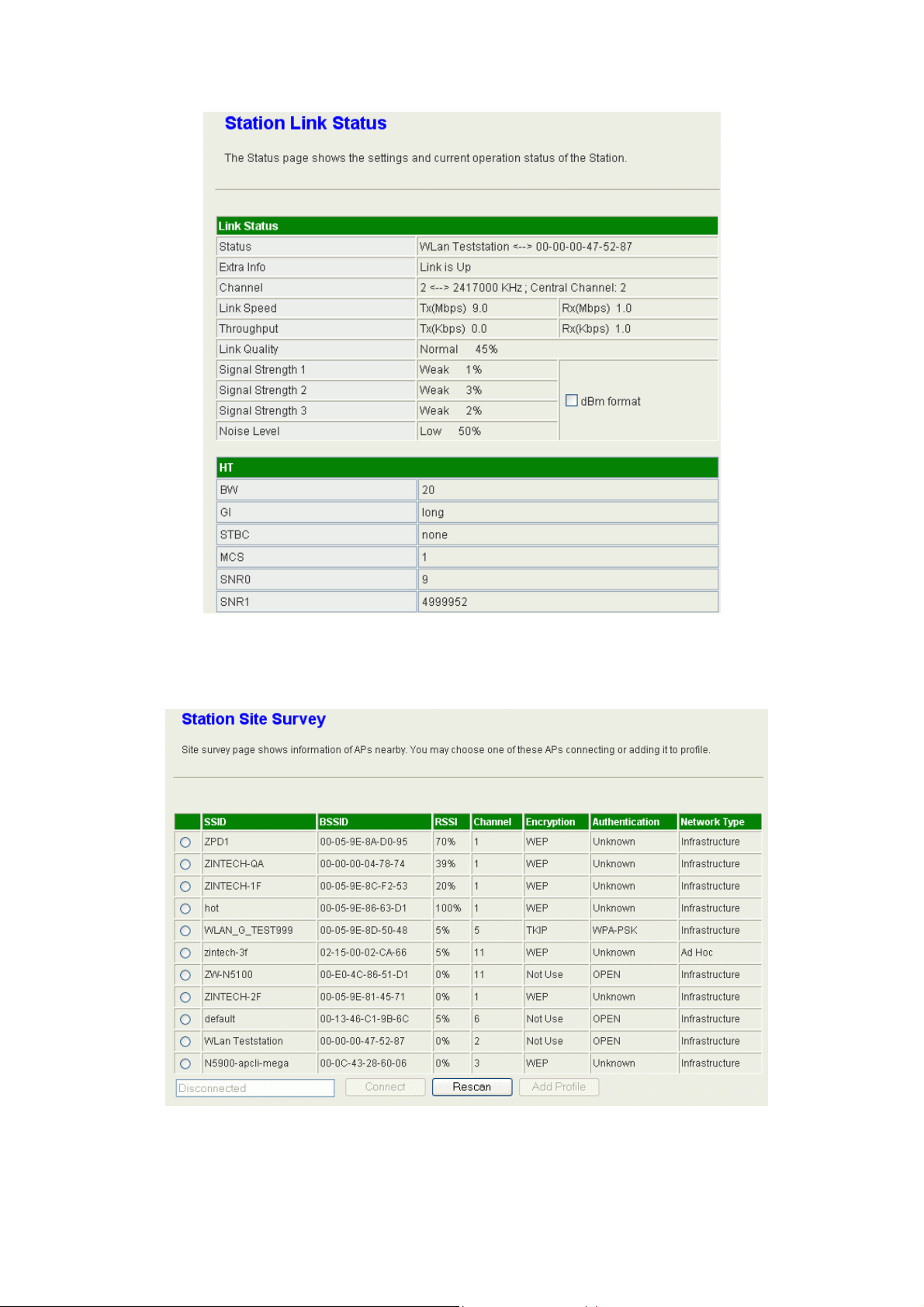
Site Survey
28
Page 29
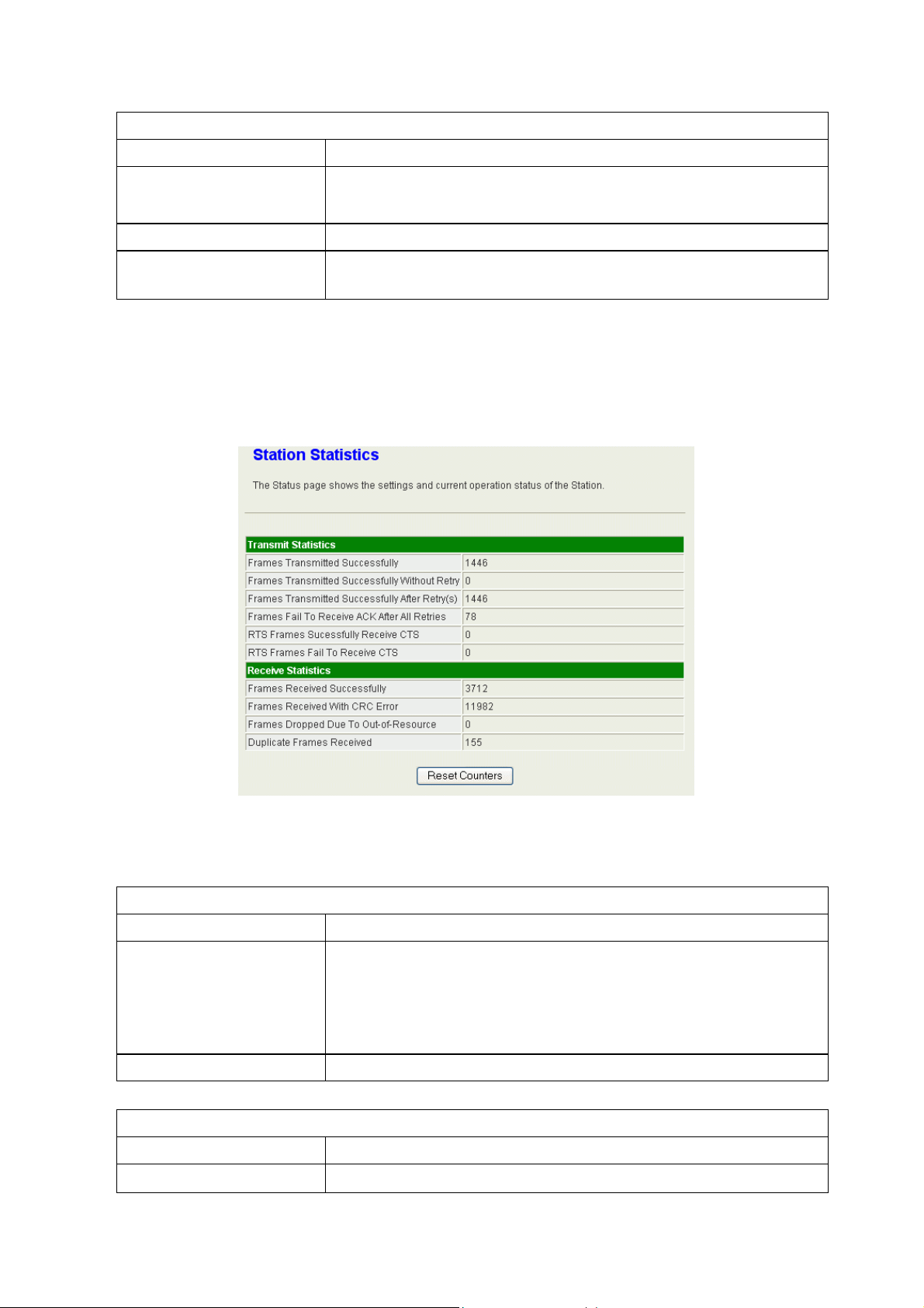
Advance Configuration
Item
Connect button
Rescan
Add Profile
Statistics
Description
Check the radio button in front of the ESSID and click
“Connect” button to connect.
Click this button to refresh the list.
Check the radio button and click this button to add the
ESSID to the profile.
Advanced
Advance Configuration
Item
Wireless Mode
(Infrastructure)
Tx Burst
HT Physical Mode
Item
HT (High throughput)
Description
Choose the WLAN type. The available options are
“802.11B/G/N mixed mode”, “802.11B Only”, “802.11G
Only”, “802.11N Only”, “802.11GN mixed mode”, and
“802.11 B/G/N mixed mode”.
This is the range of the source IP Address.
Description
MM (Mixed Mode) or GF (Green Field).
29
Page 30

Mixed mode: In this mode the device transmits the packets
with preamble compatible legacy (802.11g), so they can be
decoded by legacy devices. The device receives and
decodes both Mixed Mode packets and legacy packets.
Green Field mode: the device transmits HT packets
without legacy compatible part. But the device receives and
decodes both Green Field and legacy packets.
BW (Bandwidth) Choose “20” for the standard bandwidth or “Auto” to use
the 40MHz bandwidth automatically.
GI (Guard Interval) Choose “Long” to use long guard interval or “Auto” to setup
the GI automatically.
MCS (Modulation
Coding Scheme)
QoS
QoS Configuration
Item
WMM
WMM Power Saving
PS Mode
Choose MCS. Please refer to the section of Access Point.
Description
Check the box to enable WMM function. It depends on the
associated AP, if it sup ports WMM and you can enable this
function on this device.
Check the box to enable WMM function. It depends on the
associated AP, if it sup ports WMM and you can enable this
function on this device. When enabled, the options below
can be configured.
The options are “AC_BE”, “AC_BK”, “AC_VI” and
“AC_VO”. Please select the respective options according to
the AP.
11n Configurations
11n Configuration
Item
MPDU Aggregation
MPDU density
Aggregation MSDU
(A-MSDU)
Description
Check the box to enable this function. Click on “Manual”
radio button to setup the MPDU or “Auto” to setup
automatically.
Select the MPDU density.
The multiple HT packets can be transmitted with single
ACK reply packet. Enable it to apply this function and
reduce the network congestion.
30
Page 31
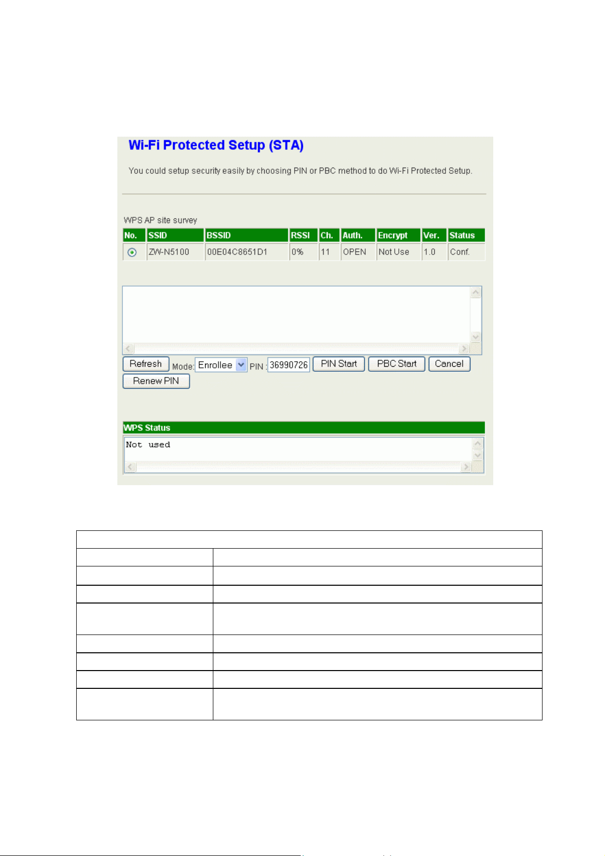
WPS
The WPS AP lists in the top of the page. The bottom panel shows the status of WPS.
Please refer to the section of Access Point mode for the operation.
11n Configuration
Item
Refresh button
Mode
PIN
PIN Start
PBC Start
Cancel
Renew PIN
Description
Click this button to refresh the WPS AP list.
This device only supports Enrollee in WLAN client mode.
This is the PIN code for PIN communication. Click “Renew
PIN” to generate a new PIN code.
Click this button to start PIN process.
Click this button to start PBC communication.
Click this button to cancel the establishing WPS link.
Click this button to discard current PIN and generate a new
PIN code.
31
Page 32

Management
Status
System Info
Item
Model
Firmware Version
System Time
Operation Mode
Local Network
Item
Local IP Address
Local Netmask
MAC Address
Wireless Information
AP mode
Item
Mode
Band
SSID
Channel
Encryption
Bssid
Associated
Clients
Driver Vision
Description
It shows the model name of the device.
It shows the version of firmware on this device.
It indicates the time on this device. If the NTP client is
enabled, the time will sync with the NTP server.
It shows the operation mode of this device.
Description
This is the IP Address of the LAN interface.
This is the Netmask for the LAN.
This is the MAC Address of the LAN interface.
Description
This is the wireless mode for the device such as AP,
client mode.
It shows the current radio mode such as “B+G+N”,
“B+G”, “B only” and “G only”.
It shows the SSID of this device.
It shows the current channel of the radio.
It indicates the encryption type for the radio.
It is the current BSSID of the radio. In this device, it is
also the MAC Address of the WLAN interface.
The number of associated WLAN clients show in this
field.
This is the driver version.
Client mode
Item
Mode
Status
Extra Info
Channel
Link speed
Link Quality
MAC Address
Driver Vision
Description
This is the wireless mode for the device such as AP,
client mode.
This is the WLAN status.
Reserved for the future expansion.
It indicates the current Wi-Fi channel.
It shows the Phy data rate of transmit and receive.
It indicates the link quality of current link.
This is the MAC Address of the radio.
This is the driver version.
32
Page 33

Statistic
Memory
Item
Memory total
Memory left
LAN
The information below shows the transmit status.
LAN Rx packets, LAN Rx bytes, LAN Tx packets, LAN Tx bytes.
All interfaces
The information likes “Rx Packet”, “Rx Byte”, “Tx Packet” and “Tx Byte” shows the status
of all interface including “eth2, lo, ra0, ra1, ra2, ra3, wds0, wds1, wds2, wds3, eth2.1,
eth2.2, br0”
Description
This is the total memory size for this device.
The available memory size shows in this field.
System Management
Administrator Settings
Enter the account for login the web interface.
Account: enter the name for login. The default name is “root”.
Password: enter the password for login. The default password is “root”.
NTP Settings
Current Time: The current time on the device shows in this field. Click “Sync” button to
sync the time with NTP server.
Time Zone: Select local time zone.
NTP Server: Input the NTP server address. If you are not sure about the local NTP server
address, you can input pool.ntp.org.
NTP synchronization (hours): This is the time interval of NTP synchronization. The range
is 1-300 hours. It is the necessary field for NTP setting and
please input it to apply.
Reboot System
Click the button to reboot the device.
Upgrade Firmware
This page provides the firmware upgrade function. Click the browse button to browse the
file and click “open” button to select the file. The upgrade process takes about 1 minute
33
Page 34

and do not power off the device during this period.
Save/Reload Settings
In this page, you can export the setting, import the setting or load the factory default.
Export Settings:
To export the settings, click “Export” button to open or save the configuration. In the pop
up window, click “Open” to open the configuration. You can read the configuration in the
next page. Click “Save” to save the configuration file. The file extension is “.dat”.
Import Settings:
To import the settings, click “Browse” to browse the file, and then click “Import” to import
the setting file.
Load Factory Defaults:
Click “Load Default” button to reset the device to factory default. All users’ settings will be
cleared.
System Command
The linux command can be input in this field. It is recommended to not to use this
function unless the experts.
System Log
The system log shows in this window. For technical support, you may need to copy and
save the log to text file and send it to the technical service. Click “Refresh” button to
refresh the page or “Clear” button to clear the log.
34
Page 35

Channel Number
The following table is the available frequencies (in MHz) for the 2.4 GHz radio:
Channel No. Frequency Country Domain
1 2412 Americas, EMEA, Japan, and China
2 2417 Americas, EMEA, Japan, and China
3 2422 Americas, EMEA, Japan, Israel, and China
4 2427 Americas, EMEA, Japan, Israel, and China
5 2432 Americas, EMEA, Japan, Israel, and China
6 2437 Americas, EMEA, Japan, Israel, and China
7 2442 Americas, EMEA, Japan, Israel, and China
8 2447 Americas, EMEA, Japan, Israel, and China
9 2452 Americas, EMEA, Japan, Israel, and China
10 2457 Americas, EMEA, Japan, and China
11 2462 Americas, EMEA, Japan, and China
12 2467 EMEA and Japan
13 2472 EMEA and Japan
14 2484 Japan only
*: EMEA (Europe, the Middle East and Africa).
The available channel is set by the factory according to the region of distribution and
can’t be changed by user. For example, the available channel of the American model is
from ch1 to ch11.
35
Page 36

Specification
Frequency Range
802.11b TX power
802.11g TX power
802.11n TX power
802.11b RX sensitivity
802.11g RX sensitivity
802.11n RX sensitivity
Data Rate
Standards
Operation Mode
2.4~2.4835GHz
17dBm ± 1dB@11Mbps
14dBm ± 1dB@54Mbps
14dBm ± 1dB@300Mbps
-89dBm ± 2dB@11Mbps
-74dBm ± 2dB@54Mbps
-66dBm ± 2dB@300Mbps
802.11b: 11, 5.5, 2, 1Mbps
802.11g: 54, 48, 36, 24, 18, 12, 9, 6Mbps
802.11n (20MHz): MCS0~15, Up to 144.4Mbps
802.11n (40MHz): MCS0~15, MCS 32, Up to 300Mbps
WLAN: IEEE 802.11 b/g, IEEE 802.11n
LAN: IEEE 802.3, IEEE 802.3u, IEEE 802.3x, IEEE 802.1d
Wireless Access Point mode,
Multi-SSID AP,
WDS,
Bridge
Security
Antenna type
Operating Environment
Power Consumption
Dimension
Software Feature
Password Protection, MAC filtering, Hidden SSID
Broadcasting, 64/128-bit WEP Encryption, WPS Push
button and PIN code, WPA for 802.1x and WPA-PSK,
WPA2 / IEEE 802.11i
2T2R 2dBi
WiFi N MODULE : antenna port x2
Temperature 0~6 C
Humidity 10~90%(non-condensing)
250Vac, 2.5A
170 x 64 x 28 mm
WLAN: b/g protection, AP Isolation, Tx Burst, Tx Short
Preamble, Packet Aggregation, HT Operation mode, HT
Guard Interval, MAC ACL, Site survey, WMM
LAN: 802.1d Spanning Tree, DHCP server
Management: NTP Client, System log, Upload config file,
Firmware upgrade, password management.
0
36
 Loading...