

Page 1
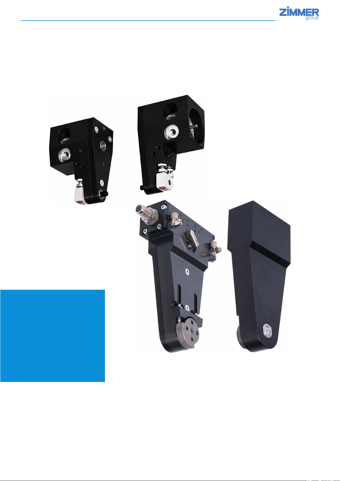
INSTALLATION AND OPERATING
INSTRUCTIONS
Handling
technology
SB/SBZ series
Swivel jaws
THE KNOW-HOW FACTORY
Page 2
INSTALLATION AND OPERATING INSTRUCTIONS: SB/SBZ series of swivel jaws
1. Supporting documents
NOTE:
The following documents are available for download on our website. Only the documents currently available on the
• Catalog
• Drawings, performance data, information about accessory parts, etc.
• Technical data (data sheets)
• General terms and conditions, including warranty information
2. Proper use
website are valid.
NOTE:
The SB/SBZ series of swivel jaws should only be used in its original state with its original accessories, without any
unauthorized changes and within the scope of its dened parameters for use.
Zimmer GmbH shall accept no liability for any damage caused by improper use
The SB/SBZ series of swivel jaws are intended to be used exclusively in pairs for picking up workpieces and for swiveling and positioning
them according to the technical design. The swivel jaws may be used only as intended and in accordance with the technical parameters.
Any use other than the intended use requires written approval from Zimmer GmbH. Modications to the swivel jaws, such as adding drill
holes or threads, may be made only with prior approval from Zimmer GmbH.
Use of the swivel jaws under extreme conditions, such as aggressive liquids and abrasive dust, is subject to prior approval from Zimmer
GmbH.
Zimmer GmbH shall accept no liability for any damage caused by improper use.
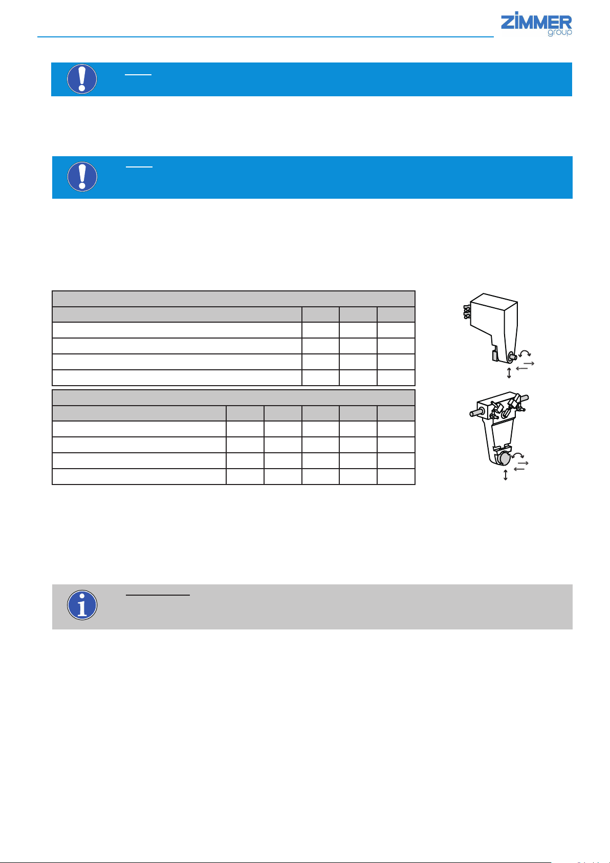
Swivel jaws of the SB series
Size 32 40 54
Torsional moment Mr [Nm]
Max. permitted force Fa [N]
Max. permitted force Fd [N]
Max. permitted force Fz [N]
2.1 10.8 15.3
180 770 850
90 385 425
90 385 425
Fa
Mr
FD
FZ
Swivel jaws of the SBZ series
Size 50 74 100 150 190
Torsional moment Mr [Nm]
Max. permitted force Fa [N]
Max. permitted force Fd [N]
Max. permitted force Fz [N]
Only the accessories permitted for this type series are allowed to be installed on the swivel jaws.
Regarding this, see Handling Technology catalog 2
When used properly, the swivel jaws of the SB/SBZ series guarantee maximum safety for people and the machine.
The swivel jaws are intended to be operated exclusively with pneumatic energy. Operation with other uid media shall be regarded as
improper use and can lead to the destruction of the swivel jaws.
15 20 70 270 600
1720 2400 4000 15000 25000
860 1200 2000 7500 12500
630 630 1200 3700 6100
Fa
Mr
FD
FZ
INFORMATION:
The swivel jaws of the SB series are always delivered in pairs.
The SBZ series swivel jaws can be ordered separately as a driven SB-...-...-B swivel jaw and as
an SB-...-G counter-support swivel jaw.
DDOC00246 enu / 2018-02-21 / b
Zimmer GmbH ● Im Salmenkopf 5 ● 77866 Rheinau, Germany ● Phone: +49 7844 9138-0
●
Fax: +49 7844 9138-80 ● www.zimmer-group.de
Page 3
INSTALLATION AND OPERATING INSTRUCTIONS: SB/SBZ series of swivel jaws
3. Function
The swivel jaws of the SB/SBZ series are designed for picking up, transporting and positioning workpieces. The installation options
have been designed so that the swivel jaws can be installed on grippers from Zimmer GmbH. The SB/SBZ series swivel jaws dier
in the mechanics of how force is transmitted and in how the drive works. The SB series is driven by a double-acting pneumatic rotary
cylinder. The force is transmitted to the output shaft by a toothed belt. The SBZ series is driven by a double-acting linear pneumatic
cylinder. The force is transmitted to the output shaft by a gear train. The rotational movement is limited by mechanical limit stops. The
line of accessories includes corresponding sensors for position sensing.
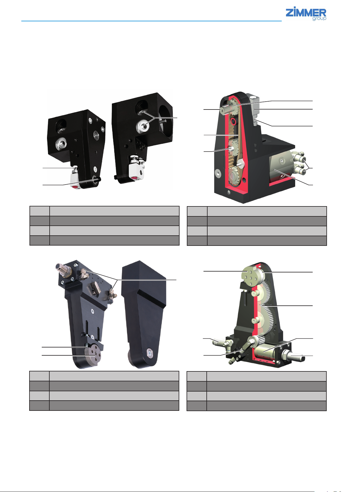
3.1. Swivel jaws of the SB series
1
7
6
4
2
3
5
5
1
Output shaft/workpiece holder
1
Double bearing for the output shaft
2
Limit stop
3
Position sensing
4
3.2. Swivel jaws of the SBZ series
6
End position
5
Force transmission
6
Energy supply
7
Drive, double-acting pneumatic rotary cylinder
8
2
7
8
1
3
8
2
Drive shaft with double bearings
1
Drive ange
2
Force transmission
3
Position sensing
4
DDOC00246 enu / 2018-02-21 / b
7
4
Drive, double-acting pneumatic rotor cylinder
5
Energy supply
6
Integrated and patented shock absorbers
7
Limit stop
8
Zimmer GmbH ● Im Salmenkopf 5 ● 77866 Rheinau, Germany ● Phone: +49 7844 9138-0
●
Fax: +49 7844 9138-80 ● www.zimmer-group.de
5
7
Page 4
INSTALLATION AND OPERATING INSTRUCTIONS: SB/SBZ series of swivel jaws
4. Technical data
Swivel jaws of the SB series **)
Size SB32-D SB40-B SB54-B
Swivel angle [°] 90/180 90/180 90/180
Torque per jaw [Nm] 0.1 0.3 1.6
Adjustable swivel angle ± [°] 3
Repeatability ± [°] 0.5
Min./max. operating pressure [bar] 3/7
Min./max. operating temperature [°C] 5/80
Cylinder volume per cycle [cm³] 2 4 16
Weight (pair) [kg] 0.3 0.7 2.2
Protection class IP 54
** Please always compare the technical data with the corresponding tables on the Internet at www.zimmer-group.de!
Swivel jaws of the SBZ series **)
Size SB50-... SB74-... SB100-... SB150-... SB190-...
90 180 G* 90 180 G 90 180 G* 90 180 G* 90 180 G*
Swivel angle
Torque per jaw
Adjustable swivel angle
Repeatability
Min./max. operating pressure
Min./max. operating temperature
Cylinder volume per cycle
Weight (individual)
Protection class
* Swivel jaw counter support, without drive power
** Please always compare the technical data with the corresponding tables on the Internet at www.zimmer-group.de!
5. Installation
[°]
[Nm]
± [°]
± [°]
[bar]
[°C]
[cm³]
[kg]
IP
90 180 - 90 180 - 90 180 - 90 180 - 90 180 -
1.2 - 3.5 10 23 - 57 -
3 - 3 3 - 3 - 3 -
0.01 0.01 0.01 0.01 0.01
3/8 3/8 3/8 3/8 - 3/8 -
5/80 5/80 5/80 5/80 5/80
5.5 7.5 - 16 21 - 40 54 - 190 260 - 320 -
0.75 0.45 1.7 1.1 4 1.5 11 6.5 28 19.5
54
WARNING:
Risk of injury in case of unexpected movement of the machine or system into which the SB/SBZ swivel jaws are to
► Switch off the energy supply to the machine before all work
► Secure the machine against being switched on unintentionally
► Check the machine for any residual energy
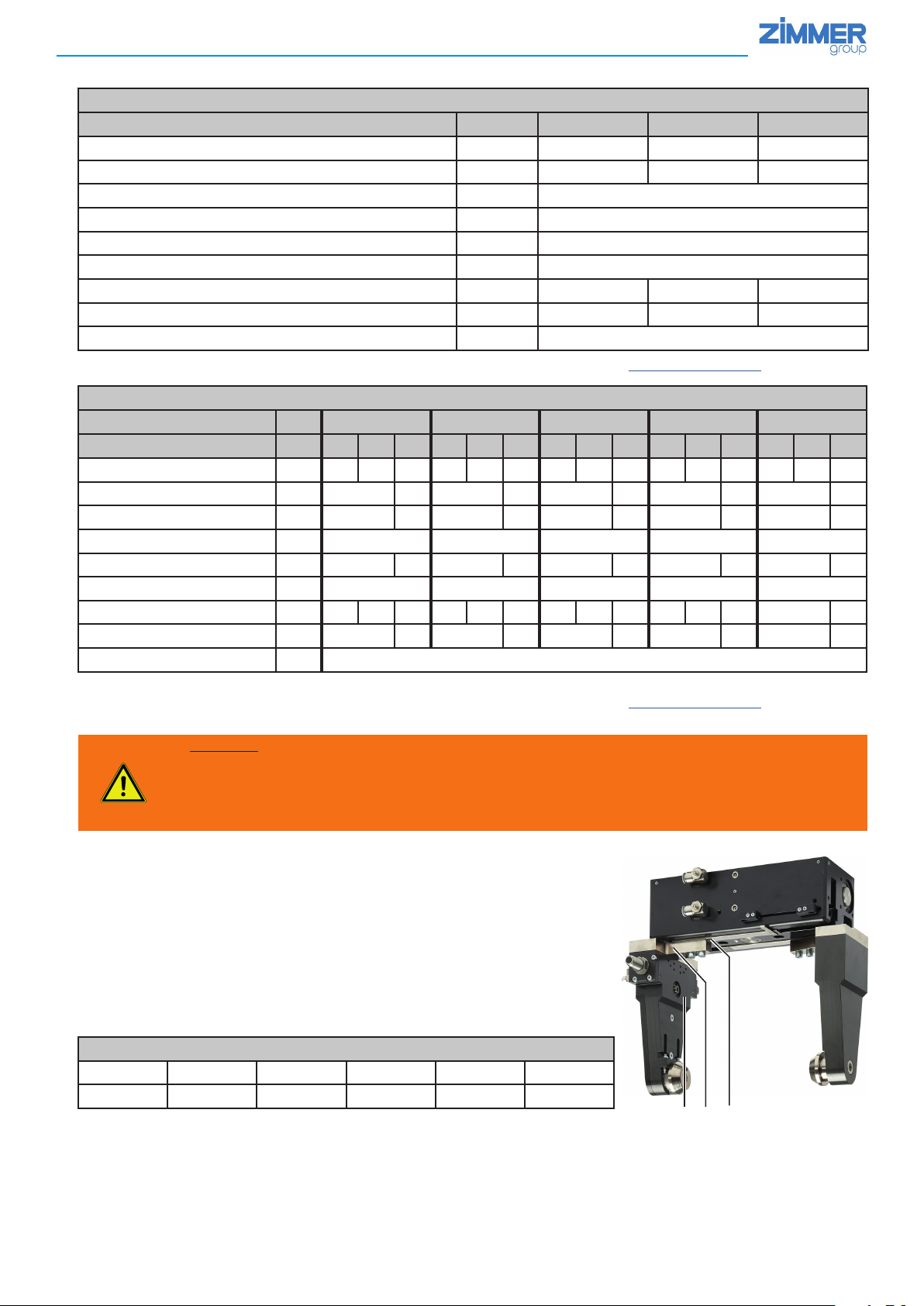
5.1 Installing the swivel jaws
The swivel jaws 1 can be installed on the jaws of parallel grippers 3 using connecting
plates
2. Each application-specic use is also possible.
be installed.
► The swivel jaws are fastened using the tapped holes
bolts are included in the scope of delivery.
In the case of customer-specific installation variants, the specified screw-in depths
and the quality of the bolts to be used must be paid attention to.
► Precise centering is accomplished by corresponding holes for straight pins
Maximum permitted tightening torque for bolts of 8.8 quality
M4 M5 M6 M8 M10 M12
3 Nm 6 Nm 10 Nm 25 Nm 49 Nm 86 Nm
DDOC00246 enu / 2018-02-21 / b
Zimmer GmbH ● Im Salmenkopf 5 ● 77866 Rheinau, Germany ● Phone: +49 7844 9138-0
4 in the housing. The assembly
5.
1 2 3
●
Fax: +49 7844 9138-80 ● www.zimmer-group.de
Page 5

INSTALLATION AND OPERATING INSTRUCTIONS: SB/SBZ series of swivel jaws
SB series
Swivel jaws of the SB series are always installed on the front side of the drive.
SBZ series
Swivel jaws of the SBZ series can be installed on the front side as well as on an interior side surface of the drive.
SB series
4 5
4 5 5 4
SBZ series
Installing the swivel jaws
Type
Installation thread x depth
4 Positioning 5
SB32-D 4 x M4 x 8 mm 2 x Ø 3H7 x 6 mm
H7
SB40-B 4 x M5 x 7 mm 2 x Ø 4
SB54-B 6 x M8 x 8 mm 2 x Ø 8
SB50-90/-180/G 4 x M5 x 8 mm 2 x Ø 4
SB74-90/-180/G 8 x M5 x 8 mm 2 x Ø 5
SB100-90/-180/G 8 x M6 x 10 mm 2 x Ø 8
SB150-90/-180/G 4 x M10 x 15 mm 2 x Ø 8
SB190-90/-180/G 4 x M12 x 12 mm 2 x Ø 10
x 6 mm
H7
x 8 mm
H7
x 5 mm
H7
x 6 mm
H7
x 10 mm
H7
x 8 mm
H7
x 10 mm
5.2 Installing base jaws/workpiece-specic jaws
SB series
SB series
To assist with installation of a base jaw or the direct
installation of a workpiece-specic application, a central
tapped hole
4 and a feather key 5 are provided on the
output shaft.
SBZ series
For the installation of workpiece-specic applications,
corresponding tapped holes
pins
5 are provided on the ange of the output shaft.
4 and holes for straight
45 4 5
Installing base jaws/workpiece-specic jaws
Type
Installation thread x depth
SB32-D 1 x M2.5 x 3 mm Output shaft with feather key
SB40-B 1 x M4 x 8 mm Output shaft with feather key
SB54-B 1 x M4 x 8 mm Output shaft with feather key
SB50-90/-180/G 1 x M5 x 8 mm 2 x Ø4
SB74-90/-180/G 1 x M6 x 8 mm 2 x Ø5
SB100-90/-180/G 1 x M8 x 12 mm 2 x Ø6
SB150-90/-180/G 4 x M8 x 12 mm 4 x Ø8
SB190-90/-180/G 4 x M10 x 14 mm 4 x Ø10
DDOC00246 enu / 2018-02-21 / b
4 Positioning 5
H7
x 4 mm
H7
x 6 mm
H7
x 6 mm
H7
x 12 mm
H7
x 12 mm
SBZ series
Zimmer GmbH ● Im Salmenkopf 5 ● 77866 Rheinau, Germany ● Phone: +49 7844 9138-0
●
Fax: +49 7844 9138-80 ● www.zimmer-group.de
Page 6

INSTALLATION AND OPERATING INSTRUCTIONS: SB/SBZ series of swivel jaws
5.3 Energy supply
The existing pneumatic connections are shown as A and B in the dimensional drawings of the product data sheets.
Alternatively, potential connections are shown with A‘ and B‘.
A/A‘: Swiveling to 90° or 180°
B/B‘: Swiveling to 0°
*) Example
Drawing SB 100-90
Type Pneumatic connections
SB32-D 4 x M5/2 x M3 -
SB40-B 2 x M5 -
SB54-B 2 x M5 -
SB50-90/-180 6 x M5 -
SB74-90/-180 6 x M5 -
SB100-90/-180 2 x M5 4 x G 1/8"
SB150-90/-180 - 6 x G 1/4"
SB190-90/-180 - 6 x G 1/4"
6. Commissioning
6.1 Adjusting the swivel angle – SB series
The swivel angle is preset to 180° at the factory (Image !)
The swivel angle can be reduced to 90°by replacing the factory-installed limit stop
(Image
@)
The swivel jaw is equipped with external limit stops
adjusted a maximum of +/- 3° per limit stop.
► Depressurize the swivel jaw
► Loosen the locknut at the respective limit stop
► Adjust the adjustment screw at the respective limit stop
It must be ensured that the adjustment screw always makes solid contact with the
respective stop surface
► Tighten the locknut
5, which allow the swivel angle to be
3.
!
3 5
DDOC00246 enu / 2018-02-21 / b
Zimmer GmbH ● Im Salmenkopf 5 ● 77866 Rheinau, Germany ● Phone: +49 7844 9138-0
@
●
Fax: +49 7844 9138-80 ● www.zimmer-group.de
Page 7

INSTALLATION AND OPERATING INSTRUCTIONS: SB/SBZ series of swivel jaws
6.2 Adjusting the swivel angle – SBZ series
The swivel angle is preset by the factory-installed ange 3
Image ! : 90 °
Image
@:180 °
The swivel jaw is equipped with external limit stops
justed a maximum of +/- 3° per limit stop.
► Depressurize the swivel jaw
► Loosen the locknut at the respective limit stop
► Adjust the adjustment screw at the respective limit stop
It must be ensured that the adjustment screw always makes solid contact with the
respective stop surface
► Tighten the locknut
6.3 Position sensing – SB series
► Before the inductive sensor 4 is installed on the swivel jaw, it has to be inserted into the
protective sleeve
► Afterwards, the inductive sensor
clamped with the corresponding stud bolt
When laying the cables, make sure they do not cross the swivel jaw's working area and
always comply with the manufacturer's specied permissible bending radius.
► Close unused sensing holes with the covers included in the scope of delivery to prevent dirt
from getting into the mechanics of the swivel jaws.
► Use stud bolts
em included in the scope of delivery.
4 can be positioned in the desired sensing hole en and
eo to clamp the covers, too.
5, which allow the swivel angle to be ad-
eo.
!
3 5
@
eo en em 4
Sensor position
Sensor position
Sensor position
6.4 Position sensing – SBZ series
► Before the inductive sensors are installed, the mounting blocks ep (deliverable as
accessories) have to be installed.
To do so, see the dimensional drawings on the product data sheets at
www.zimmer-group.de
► Afterwards, the inductive sensors
positioned and clamped.
Inductive sensor NJ8-E2S:
Rated switching distance S
Stored switching distance S
Real switching distance S
When laying the cables, make sure they do not cross the swivel jaw's working area
and always comply with the manufacturer's specied permissible bending radius.
► The switch cams
the interior or exterior of the swivel jaws.
eq and the clamping blocks for the inductive sensors can be installed on
4 can be pushed into the mounting blocks,
= 2.00 mm
n
= 1.60 mm
a
= 2.20 mm
r
A: Swivel angle 0°
B: Swivel angle 90°
C: Swivel angle 180°
A
4 ep eq
B
C
DDOC00246 enu / 2018-02-21 / b
Zimmer GmbH ● Im Salmenkopf 5 ● 77866 Rheinau, Germany ● Phone: +49 7844 9138-0
●
Fax: +49 7844 9138-80 ● www.zimmer-group.de
Page 8

INSTALLATION AND OPERATING INSTRUCTIONS: SB/SBZ series of swivel jaws
6.5 End position damping – SBZ series
NOTE:
Always ensure that the adjustment screws make contact with the respective limit stop surfaces, so that the shock
absorber does not serve as an end stop.
The following steps should be carried out to adjust the end position damping
► Loosen the shock absorber locknut
the drive ange
► Unscrew the shock absorber by 3-4 turns counterclockwise (decreases damping)
► Loosely attach the locknut
► Remove persons, all tools and other objects from the swivel range of the swivel jaws
► Connect the swivel jaws to the energy supply and ll them with properly prepared air
► Open the adjustment screws of the ow control valves
► Pressurize the swivel jaws with compressed air on alternating sides and check the settings
► If necessary, make adjustments using the adjustment screws of the ow control valves and
by adjusting the shock absorber
► Clamp the shock absorber locknuts
An ideal setting is reached if a uniform swivel movement and an approach to the limit stops with
exhaust air throttling is guaranteed.
7. Maintenance
► The swivel jaws of the SB/SBZ series operate maintenance-free for up to 10 million swiveling cycles.
1 moves
hm and turn the shock absorber hn clockwise until
ho by a few turns
7:
ho hm hn
INFORMATION:
The actual service life of the swivel jaws is dependent on many factors:
•Drive with ltered compressed air, dry or lubricated
If operation begins with lubricated air, then the swivel jaws must always be operated
• Operation in one direction, operation with change of direction
• Environmental conditions (humidity, temperature, etc.)
• The performance data for the corresponding use/handling weight
• Shock absorber setting
Driven with compressed air in accordance with ISO 8573.1 with the following parameters:
- Solid content class 2
- Moisture content class 4
- Oil content: Class 1 (non-lubricated air)
Despite the aforementioned maintenance-free feature, we recommend regularly checking the swivel jaws in accordance with the general duty to exercise proper care. For this purpose, we recommend the intervals listed in the table.
with lubricated air after that
Interval Maintenance work Description
Check for damage, corrosion, contamination
Strength of all threaded connections, function of all movable elements
1 monthly Visual inspection
2 monthly Cleaning
Freedom of movement of all hoses and lines
Leaking at the pneumatic connections
Function of the sensors and the electrical connections
Cleanliness of the sensors and contact stability of the connections
Cleanliness of the surfaces and contact elements for the workpiece holder
Apply corrosion protection agent to the housing
INFORMATION:
Complete removal of the swivel jaws can only be carried out by Zimmer.
DDOC00246 enu / 2018-02-21 / b
Zimmer GmbH ● Im Salmenkopf 5 ● 77866 Rheinau, Germany ● Phone: +49 7844 9138-0
●
Fax: +49 7844 9138-80 ● www.zimmer-group.de
Page 9

INSTALLATION AND OPERATING INSTRUCTIONS: SB/SBZ series of swivel jaws
8. Declaration of incorporation in terms of the EC Machinery Directive 2006/42/EC on Machinery (Annex II 1 B)
In terms of the EU Machinery Directive 2006/42/EC (Annex II 1 B)
Name and address of the manufacturer:
Zimmer GmbH, Im Salmenkopf 5, 77866 Rheinau, Germany
We hereby declare that the incomplete machines described below
Product designation: Swivel jaw
Type designation: SB/SBZ
satisfy the following basic requirements of the Machinery Directive 2006/42/EC:
No. 1.1.2., No. 1.1.3., No. 1.1.5., No. 1.3.2., No. 1.3.4., No. 1.3.7., No. 1.5.3., No. 1.5.4., No. 1.5.8., No. 1.6.4., No. 1.7.1., No. 1.7.4.
We also declare that the specic technical documents were produced in accordance with Annex VII Part B of this Directive.
We undertake to provide the market supervisory bodies with electronic versions of special documents for the incomplete machine
through our documentation department, should they have reason to request them.
The incomplete machine may only be commissioned if the machine or system in which the incomplete machine is to be installed
has been determined to satisfy the conditions of the Machinery Directive 2006/42/EC and the EC Declaration of Conformity has
been produced in accordance with Annex II 1 A.
Authorized representative for compiling the
relevant technical documents
Kurt Ross See manufacturer's address Rheinau, Germany, 2015-05-04 Martin Zimmer
First name, last name Address (Place and date of issuing) (Legally binding signature)
Managing Director
DDOC00246 enu / 2018-02-21 / b
Zimmer GmbH ● Im Salmenkopf 5 ● 77866 Rheinau, Germany ● Phone: +49 7844 9138-0
●
Fax: +49 7844 9138-80 ● www.zimmer-group.de
Page 10

INSTALLATION AND OPERATING INSTRUCTIONS: SB/SBZ series of swivel jaws
9. Your notes
DDOC00246 enu / 2018-02-21 / b
Zimmer GmbH ● Im Salmenkopf 5 ● 77866 Rheinau, Germany ● Phone: +49 7844 9138-0
●
Fax: +49 7844 9138-80 ● www.zimmer-group.de
Page 11

INSTALLATION AND OPERATING INSTRUCTIONS: SB/SBZ series of swivel jaws
DDOC00246 enu / 2018-02-21 / b
Zimmer GmbH ● Im Salmenkopf 5 ● 77866 Rheinau, Germany ● Phone: +49 7844 9138-0
●
Fax: +49 7844 9138-80 ● www.zimmer-group.de
Page 12

INSTALLATION AND OPERATING INSTRUCTIONS: SB/SBZ series of swivel jaws
DDOC00246 enu / 2018-02-21 / b
Zimmer GmbH ● Im Salmenkopf 5 ● 77866 Rheinau, Germany ● Phone: +49 7844 9138-0
●
Fax: +49 7844 9138-80 ● www.zimmer-group.de
 Loading...