

Page 1

INSTALLATION AND OPERATING INSTRUCTIONS: Pneumatic gripper, GPP/GPD5000 series
bl
bo
bn
1 Supporting documents
NOTICE:
Read through the installation and operating instructions carefully before installing the product!
The installation and operating instructions contain important notes for your personal safety. They must be read
and understood by all persons who work with or handle the product during any phase of the product life time.
The documents listed below are available for download on our website.
Ö www.zimmer-group.com
Only the documents currently available on the website are valid.
• Catalogs, drawings, CAD data, performance data
• Information on accessories
• Detailed installation and operating instructions
• Technical data sheets
• General Terms and Conditions of Business, including warranty information
2 Safety notices
CAUTION:
Non-compliance may result in severe injuries!
The following notes shall be taken into account in order to reduce the likelihood of injuries/malfunctions:
1. Installation, commissioning, maintenance and repairs may only be performed by qualied experts in accor-
dance with these installation and operating instructions.
2. The gripper is state-of-the-art. It is mounted on industrial machines.
3. The gripper may be used only in accordance with its proper use and technical data. Zimmer GmbH shall
accept no liability for any damage caused by improper use.
4. Any use other than the intended use requires written approval from Zimmer GmbH.
5. Do not reach into the operational range of the gripper.
6. Make sure that the power supplies are disconnected before you install, modify or maintain the gripper.
7. In case of maintenance, conversion or expansion work, remove the gripper from the machine and perform
the work outside the danger zone.
8. When commissioning or testing, make sure that the gripper cannot be actuated by mistake.
9. Modications to the gripper, such as adding drilled holes or threads, may be made only with prior approval
from Zimmer GmbH.
10. The specied maintenance intervals and compressed air quality specications are to be observed; also refer
to the "Maintenance" section. Please contact Zimmer Customer Service for this purpose.
11. Use of the gripper under extreme conditions, such as aggressive liquids and abrasive dusts, is subject to
prior approval from Zimmer GmbH.
12. When disassembling grippers with integrated springs, exercise heightened caution because spring tension
is always present.
3 Proper use
NOTICE:
The GPP/GPD5000 series gripper is only to be used in its original state with its original accessories, with no
unauthorized changes and within the scope of its dened parameters for use.
Zimmer GmbH shall accept no liability for any damage caused by improper use.
The gripper is designed for operation with compressed air only. It is not suited for operation with other media such as
liquids or gases. The gripper is used as dened under "Proper use" in enclosed rooms to temporarily grip, handle and hold
parts.
Proper use of the gripper includes noting and observing the maximum permissible forces and torques (see technical data
sheets at www.zimmer-group.com).
4 Personnelqualication
Installation, commissioning and maintenance may only be performed by qualied personnel. These persons must have
read and understood the installation instructions in full.
5 Product description
Alternating ventilation moves the internal drive up and down. The movement generated in this process is transferred to
the gripper jaws by kinematics, producing the gripper jaw movement. For grippers with an integrated spring, this spring
supports the grip force, acting in the force-transfer direction.
Fig. 1: Cutaway view of the GPP5000 series gripper
Installation and
operating instructions
GPP/GPD5000 series
DDOC00196
Index g
EN / 8/13/2019
6 Installation
NOTICE:
Switch o the power supply before any assembly, installation or maintenance work.
CAUTION:
Switch o the power supply before any assembly, installation or maintenance work.
► Switch o the pneumatic power supply prior to all work.
► Secure the pneumatic power supply against being switched on unintentionally.
► Depressurize and check the pneumatic system.
Ö When doing this, pay attention to stored (built-up) energy!
WARNING:
Risk of injury in case of unexpected movement of the machine or system into which the gripper is to be
installed.
► Switch o the power supply to the machine before all work.
► Secure the machine against being switched on unintentionally.
► Check the machine for any residual energy.
► For spring-assisted grippers, wait until the gripper ngers have reached the end position with the system
depressurized.
In the event of overhead assembly of the gripper with a dead weight under 3 kg, the gripper can be installed by
a single person.
In the event of overhead assembly of the gripper with a dead weight exceeding 3 kg, work must be carried out
with lifting equipment.
The gripper must be installed on a mounting surface in accordance with the levelness specications.
Length/diameter < 100 mm permitted unevenness ≤ 0.02 mm
Length/diameter > 100 mm permitted unevenness ≤ 0.05 mm
Ö Gripper (GPP/GPD): Use mounting screws of strength class 8.8 Ö DIN EN ISO 4762.
Ö Gripper ngers (GPD): Use mounting screws of strength class 12.9 Ö DIN EN ISO 4762.
Ö The mounting screws are not included in the scope of delivery.
Ö Screw-in depth ≥ 1.5xØ
Ö Observe the tightening torque of the mounting screws.
Ö Make sure the mounting surface is suciently rigid and level.
6.1 Installing the GPP5000 series
Im Salmenkopf
77866 Rheinau,
Germany
+49 7844 9138 0
+49 7844 9138 80
www.zimmer-group.de
Wiper with double-lip seal
1
Positively driven wedge hook trans-
2
mission
Integrated gripping force safety device
3
Drive
4
Gripper nger
5
Linear steel guide
6
Mounting block
7
Integrated slot
8
Mounting and positioning
9
Fig. 2: Cutaway view of the GPD5000 series gripper
5.1 IP protection class
The following IP protection classes apply to the dierent gripper variants.
IP protection class Variant
IP40
IP64 double-lip seal
IP67 protector version with sealing air (max. 0.5
bar)
AL 00 20 21 24
The gripper can be installed at its base or side surface onto a mounting piece. When doing so, make sure the
levelness specications are adhered to.
The following work steps must be observed when installing at the base or side surface:
► Insert centering sleeves
► Use centering sleeves bm to position the gripper on the mounting piece.
► Use mounting screws
Ö Note that mounting screws of dierent sizes may need to be used during installation, depending on the
installation method.
bm in designated ts bn.
bl to mount the gripper onto the mounting piece.
6.2 Installing the GPD5000 series
The gripper can be installed onto a mounting piece
using its base. When doing so, make sure the level-
ness specications are adhered to.
The following work steps must be observed when
installing at the base:
► Insert straight pins bo in the designated ts bn.
► Use the straight pins bo to position the gripper on
the mounting piece.
► Use mounting screws bl to mount the gripper
onto the mounting piece.
X
X X
X X
Zimmer GmbH
●
Im Salmenkopf 5 ● 77866 Rheinau, Germany ● +49 (0) 7844 9138 80
●
+49 7844 9138 80
●
www.zimmer-group.com
Page 2
INSTALLATION AND OPERATING INSTRUCTIONS: Pneumatic gripper, GPP/GPD5000 series
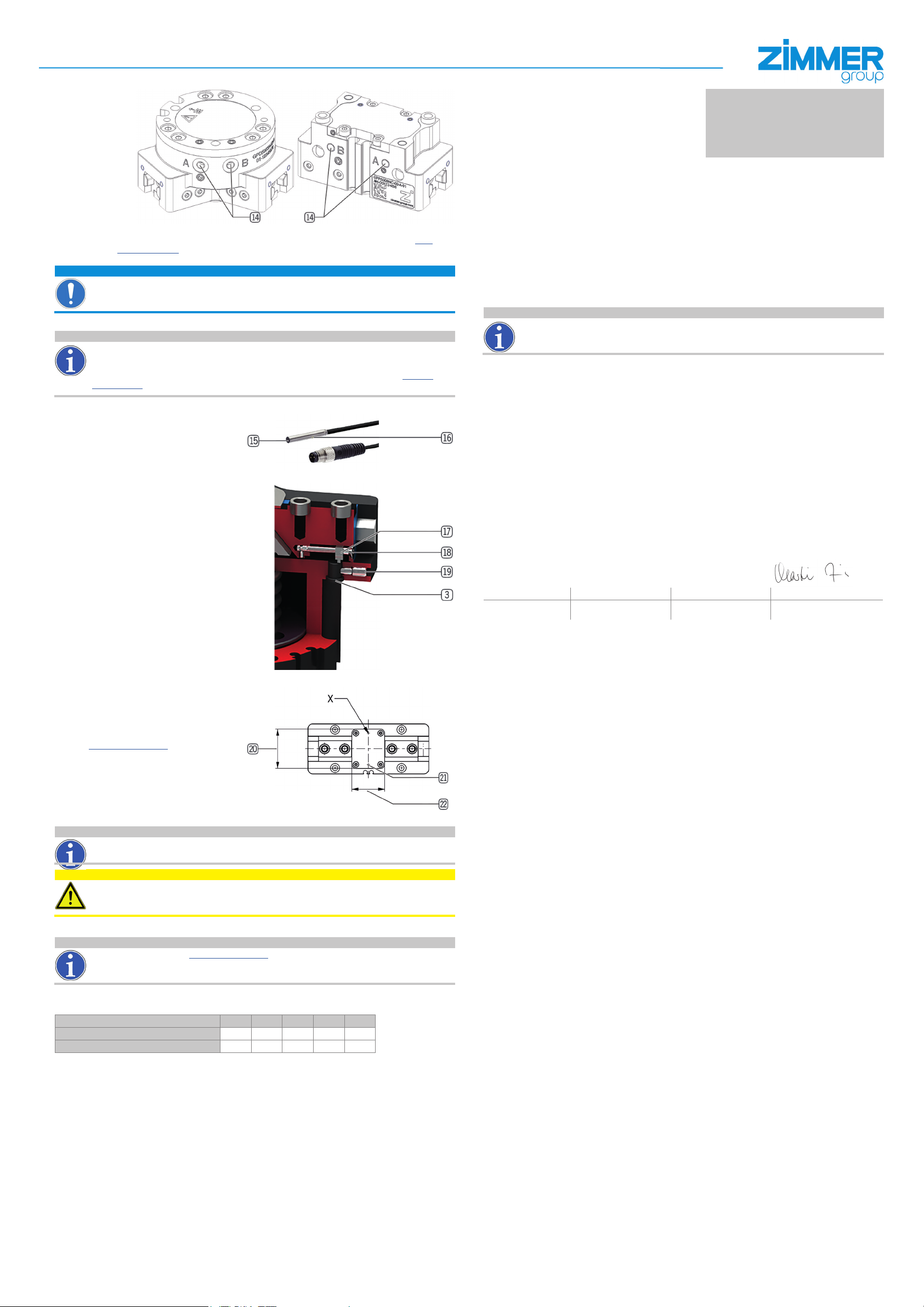
6.3 Power supply installation
9 Transport/storage/preservation
► The transport and storage of the gripper must take place exclusively in the original packaging.
► If the gripper has already been installed on the higher-level machine unit, it must be ensured during transport that no
uncontrolled movements take place. Before commissioning the machine after transport, check all power and communication connections as well as all mechanical connections.
► If the product is stored for an extended period, the following points are to be observed:
Ö Keep the storage location as dust-free and dry as possible.
Power supply bp is located laterally on the housing.
Ö The exact positions are referenced in the technical data sheet, which you can view online at www.
zimmer-group.com.
Ö Refer to the technical data sheet for alternative power supply positions!
NOTICE:
Close o the unused pneumatic connections with dummy plugs.
Use compressed air in accordance with DIN ISO 8573-1 [4:4:4].
6.4 Installation of accessories
INFORMATION:
If any accessories not marketed or authorized by Zimmer GmbH are used, the function of the gripper cannot be
guaranteed.
The accessories from Zimmer GmbH are specically tted for the individual grippers.
Corresponding optional accessories and those included in the scope of supply can be found at www.zim-
mer-group.com.
6.6 Installing and adjusting inductive proximity switches
Using the inductive proximity switches, any
desired position of the gripper ngers can be
detected directly at the mechanical system.
Inductive proximity switches can be used in
ascending order starting from sizes GPP/GPD
5006!
The following variants are excluded:
GPP/GPD50-AL-A
The following work steps must be observed when
installing/adjusting inductive proximity switches:
► Insert the inductive proximity switch
designated mounting block
► Slide in as far as it will go and secure with
clamping screw bu.
► Connect the inductive proximity switch bq to
the operating voltage (10 - 30 V DC).
► Bring the gripper jaws into the desired grip-
ping position.
► Adjust the cam switch bs using the setscrew
bq in
3.
bt until the function display br illuminates on
the inductive proximity switch.
► The inductive proximity switch bq is ready for
operation.
10 Decommissioning and disposal
11 Declaration of Incorporation
Ö Avoid temperature uctuations/observe and adhere to the temperature range.
Ö Avoid wind/drafts/water condensation formation.
Ö Store product packaged.
Ö During storage, it must be kept from direct sunlight.
► Visually inspect all of the components.
► Remove all foreign objects.
► Close pneumatic connections using suitable covers.
INFORMATION:
If the gripper reaches the end of its operational phase, it can be completely disassembled and disposed of
according to material groups. Disconnect the gripper from the power supply completely. When disposing of it,
observe the locally applicable environmental regulations and codes and regulations for disposal.
In terms of the EU Machinery Directive 2006/42/EC (Annex II 1 B).
Name and address of the manufacturer:
Zimmer GmbH, Im Salmenkopf 5, 77866 Rheinau, Germany +49 7844 9138 0, +49 7844 9138 80,
www.zimmer-group.com
We hereby declare that the incomplete machine described below
Product designation: Gripper, pneumatic
Type designation: GPP/GPD5 series
satises the following basic requirements of the Machinery Directive 2006/42/EC:
No. 1.1.2., No. 1.1.3., No. 1.1.5., No. 1.3.2., No. 1.3.4., No. 1.3.7., No. 1.5.3., No. 1.5.4., No. 1.5.8., No. 1.6.4., No. 1.7.1., No.
1.7.4
We also declare that the specic technical documents were produced in accordance with Annex VII Part B of this Directive.
We undertake to provide the market supervisory bodies with electronic versions of special documents for the incomplete
machine through our documentation department, should they have reason to request them.
The incomplete machine may only be commissioned if it has been ascertained, if applicable, that the machine or
system in which the incomplete machine is to be installed satises the requirements of Directive 2006/42/EC on
Machinery and an EC Declaration of Conformity has been drawn up in accordance with Annex II 1 A.
Authorized representative for the compilation of
relevant technical documents
Kurt Ross See manufacturer's address Rheinau, Germany, 8/1/2019 Martin Zimmer
First name, last name Address Place and date of issuance
Installation and
operating instructions
GPP/GPD5000 series
DDOC00196
Index g
EN / 8/13/2019
(Legally binding signature)
Managing Director
Im Salmenkopf
77866 Rheinau,
Germany
+49 7844 9138 0
+49 7844 9138 80
www.zimmer-group.de
6.7 Installingacustomer-specicsupport
structure
It is possible to remove the cover plate cm
installed by the manufacturer in order to use a
customer-specic support structure.
The dimensions required for the customer-spe-
cic support structure are referenced in the
technical data sheet found on our website at
Ö www.zimmer-group.com
The dimension cn must under no circum-
stances be exceeded by the customer-specic
support structure. The support structure must
be designed such that it does not impede the
movement of the gripper jaws.
The dimension cl may be exceeded by the
customer-specic support structure.
There are additional blind holes with ts for a customer-specic connection below the cover plate cm.
INFORMATION:
Make sure to observe the following for GPD5000 series grippers:
If the gripper has been mounted using a pressure piece, no additional support structure can be incorporated.
CAUTION:
Non-compliance may result in injuries!
The customer-specic support structure must not collide with other parts of the machine in which the gripper is
installed while the gripper is moving.
7 Technical data
INFORMATION:
Please refer to our website Ö www.zimmer-group.com for technical data.
This data varies within the series depending on the specic design. If you should have further questions about
products or technical data, please contact Zimmer GmbH Customer Service.
8 Maintenance
Maintenance-free operation of the dierent gripper variants is ensured within the following parameters.
Cycles Variant AL 00 20 21 24
15 million maintenance-free cycles (max.)
30 million maintenance-free cycles (max.)
The maintenance interval may shorten under the following circumstances:
• Operation with compressed air that does not comply with DIN ISO 8573-1 [4:4:4].
• Dir ty environment.
• Improper use and use that does not comply with the power specications.
• Ambient temperature of above 60 °C
Even though the gripper is, as mentioned, maintenance-free, perform a regular visual inspection to check for any damage
or contamination.
We recommend using Zimmer Customer Service for maintenance.
Dismantling and reassembling the gripper without authorization may result in complications, as special installation equipment is required in some cases.
Zimmer GmbH shall not be liable in the event of unauthorized dismantling and reassembling of the gripper or in the event
of any malfunction or damage resulting from this.
X
X X X X
Zimmer GmbH
●
Im Salmenkopf 5 ● 77866 Rheinau, Germany ● +49 (0) 7844 9138 80
●
+49 7844 9138 80
●
www.zimmer-group.com
 Loading...