

Page 1
INSTALLATION AND
OPERATING INSTRUCTIONS
Handling
technology
GPP/GPD5000IL series
"The Hybrid"
THE KNOW-HOW FACTORY
Zimmer GmbH ● Im Salmenkopf 5 ● 77866 Rheinau, Germany ● Phone: +49 7844 9138-0
Link
IO-
www.IO-Link.com
●
Fax: +49 7844 9138-80 ● www.zimmer-group.de
Page 2

INSTALLATION AND OPERATING INSTRUCTIONS: Pneumatic gripper, intelligent GPP/GPD5000IL series
Content:
1. Supporting documents 3
2. Proper use 3
3. Personnel qualication 3
4. Safety notes 3
5. Product description 4
5.1 GPP5000IL function (NO/NC) 4
5.2 GPD5000IL function (NO/NC) 5
5.3 GPP/GPD5000IL function (N) 5
6. Installation 5
6.1 Safety notes 5
6.2 Installing the gripper 5
6.3 Installing the gripper ngers 6
6.4 Static charge 6
6.5 Inuencing the position sensor 6
6.6 Pneumatic connection 6
7. Commissioning 6
7.1 IO-Link commissioning 6
7.2 Control 7
7.3 LED display 8
7.4 Process data 8
7.5 Control with cyclical process data 9
7.5.1 Procedure for data transfer 9
7.5.2 "ControlWord" parameter 10
7.5.3 "DeviceMode" parameter 11
7.5.4 "WorkpieceNo." parameter 11
7.5.5 "TeachPosition" parameter 12
7.5.6 "PositionTolerance" parameter 12
7.5.7 "StatusWord" parameter 13
7.5.8 "Diagnosis" parameter 13
7.5.9 "ActualPosition" parameter 14
7.6 Sensing of end positions 14
7.7 Service parameters 14
7.7.1 StatusWord 0x40 14
7.7.2 Diagnostics 0x41 14
7.7.3 Cycle counter 0x42 15
7.7.4 System temperature 0x43 15
7.7.5 ControlWord 0x44 15
7.7.6 Error code 0x45 15
7.7.7 Error code 0x46 15
7.7.8 Operating seconds counter 0x47 15
7.7.9 ActualPosition 0x100 16
7.7.10 TeachPosition 0x101 16
7.7.11 WorkpieceNo. 0x102 16
7.7.12 DeviceMode 0x103 16
7.7.13 PositionTolerance 0x104 16
7.7.14 Current operating pressure 0x110 16
7.7.15 Pressure switch bottom 0x111 17
7.7.16 Pressure switch top 0x112 17
7.7.17 Pressure hysteresis 0x113 17
7.7.18 Base/Work position switching thresholds 0x114 17
7.7.19 Movement detection 0x115 17
8. Error diagnostics 18
9. Accessories 19
10. Glossary 20
11. Maintenance 21
12. Fault exclusion 21
13. Installer's Declaration (in accordance with the Machinery Directive) 22
14. Declaration of Conformity (in accordance with the EMC Directive) 23
15. Your notes 24
DDOC00247 enu / 2018-09-14 / Index a
Zimmer GmbH ● Im Salmenkopf 5 ● 77866 Rheinau, Germany ● Phone: +49 7844 9138-0
●
Fax: +49 7844 9138-80 ● www.zimmer-group.de
2
Page 3
INSTALLATION AND OPERATING INSTRUCTIONS: Pneumatic gripper, intelligent GPP/GPD5000IL series
1. Supporting documents
Note:
The following documents are available for download on our website.
Only the documents currently available on the website are valid.
• Catalog
• Drawings, performance data, information about accessory parts, etc.
• General terms and conditions, including warranty information
2. Proper use
Note:
The gripper should only be used in its original state with its original accessories, without any unauthorized
changesandwithinthescopeofitsdenedparametersforuse.
Zimmer GmbH shall accept no liability for any damage caused by improper use.
The gripper is designed exclusively for operation using a 24 V DC power supply.
The operating pressure is in the range of 3-8 bar for standard grippers and 4-7 bar for the respective NC/NO versions.
The gripper is used as dened under "Proper use" in enclosed rooms to temporarily grip, handle and hold parts.
The gripper is not suitable for clamping workpieces during a machining process.
Direct contact with perishable goods/food is not permitted.
3. Personnel qualications
Installation, commissioning and operation may be undertaken by trained specialists only. They must have read and understood the
installation and operating instructions in full.
4. Safety notes
1. Installation, commissioning, maintenance and repairs may only be performed by qualied experts in accordance with
these installation and operating instructions.
2. The gripper is state-of-the-art. It is tted to industrial machines and is used to hold workpieces. The following are ex-
amples of situations in which the gripper may cause a hazard:
- the gripper is not properly tted, used or maintained
- the gripper is not used for its intended purpose
- failure to observe the local regulations (legislation, guidelines, directives), such as the EC Machinery
Directive,
- the Accident Prevention Regulations (UVV) and the assembly and operating instructions
are not observed.
3. The gripper may be used only in accordance with its proper use and technical data.
ZIMMER GmbH shall accept no liability for any damage caused by improper use.
4. Any use other than the proper use requires written approval from Zimmer GmbH
5. Make sure that the energy supply is disconnected and before you install, retool, maintain or repair the gripper.
6. In case of maintenance, renovation or expansion work, remove the gripper from the machine and carry out the work
outside the danger zone.
7. When commissioning or testing, make sure that the gripper cannot be actuated by mistake.
8. Modications to the gripper, such as adding drill holes or threads, may be made only with prior approval from Zimmer
GmbH.
9. The specied maintenance intervals and compressed air quality specications are to be observed; also refer to the
Maintenance section. When using the gripper under extreme conditions (see Item 11), the maintenance interval must
be adapted depending on the extent of the contamination. Please contact our hotline for this purpose.
10. Use of the gripper under extreme conditions, such as aggressive liquids and abrasive dust, is subject to prior approval
from Zimmer GmbH
11. When disassembling grippers with integrated springs, exercise increased caution because spring tension is always
present.
DDOC00247 enu / 2018-09-14 / Index a
Zimmer GmbH ● Im Salmenkopf 5 ● 77866 Rheinau, Germany ● Phone: +49 7844 9138-0
●
Fax: +49 7844 9138-80 ● www.zimmer-group.de
3
Page 4
INSTALLATION AND OPERATING INSTRUCTIONS: Pneumatic gripper, intelligent GPP/GPD5000IL series
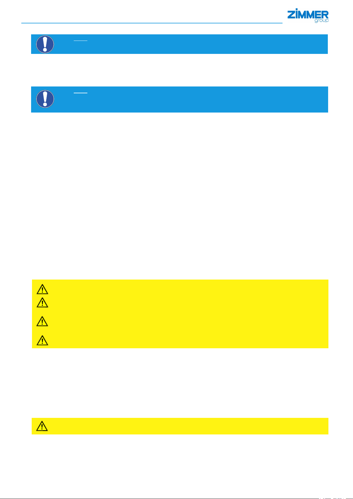
5. Product description
• Alternating ventilation moves the internal pneumatic piston 1
up and down.
• The power generated in this process is transferred 2 to
the gripper jaws 3 via a kinematic system to produce the
gripping force.
• The double-lip seal 5 reliably prevents lubricant from
escaping and guarantees protection with IP 64 from the
exterior.
• Integrated gripping force safety device 4 (only for NC / NO)
Spring inserted in the cylinder chamber used for energy
storage
• The pneumatic piston is controlled by integrated
3/2 NC 24 V DC directional valves. 6
• Communication is carried out over an IO-Link interface 7.
3
2
5
4
1
6
7
The 3-jaw concentric grippers from the GPD5000IL series
operate according to the same principle.
3
2
5
4
1
7
6
INFORMATION:
Useofltered,compressedair,oil-free,inaccordancewithENISO8573-1,Class3.4.3
Note:
The gripping force safety device with an integrated spring as an energy storage unit is only available
fortheNCandNOversions.TheNversionhasno gripping force safety device in either gripping direction.
5.1 GPP5000IL function (NO/NC)
The gripper ngers of the parallel gripper are arranged successively on two shared
steel guide rails and can be moved alongside each other.
Compressed air that moves a piston is used to supply power.
The stroke movement of the piston is diverted to both gripper jaws via a connecting rod.
This generates the movement of the gripper jaws.
An internal spring is used to retain the gripping force when there is a drop in pressure.
The gripper is suitable for outward gripping. (NO = normally open)
The gripper is suitable for inward gripping. (NC = normally closed)
DDOC00247 enu / 2018-09-14 / Index a
Zimmer GmbH ● Im Salmenkopf 5 ● 77866 Rheinau, Germany ● Phone: +49 7844 9138-0
NO NC
●
Fax: +49 7844 9138-80 ● www.zimmer-group.de
4
Page 5
INSTALLATION AND OPERATING INSTRUCTIONS: Pneumatic gripper, intelligent GPP/GPD5000IL series
5.2 GPD5000IL function (NO/NC)
The gripper ngers of the three-jaw gripper are each positioned between two
steel guide rails.
Compressed air that moves a piston is used to supply power.
The stroke movement of the piston is diverted to both gripper jaws via a
connecting rod.
This generates the movement of the gripper jaws
An internal spring is used to retain the gripping force when there is a drop in
pressure.
The gripper is suitable for outward gripping. (NO = normally open)
The gripper is suitable for inward gripping. (NC = normally closed)
NO
5.3 GPP/ GPD5000IL function (N)
The gripper ngers of the three-jaw gripper are each positioned between two
steel guide rails.
Compressed air that moves a piston is used to supply power.
The stroke movement of the piston is diverted to both gripper jaws via a
connecting rod.
This generates the movement of the gripper jaws.
There is no gripping force retention in the event of a pressure or voltage loss.
The gripper is suitable for outward or inward gripping.
NC
6. Installation
6.1 Safety notes
CAUTION:
Bleed the pressure supply and switch o the power supply for the electronics before any assembly, installation
or maintenance work.
► Risk of injury
6.2 Installing the gripper
The gripper can be installed from several sides on a mounting surface that meets the specications for evenness.
If the length of the mounting surface is <100 mm, the permitted unevenness is <0.02 mm.
If the length of the mounting surface is >100 mm, the permitted unevenness is <0.05 mm.
The following work steps are to be carried out to install the gripper:
► Insert centering sleeves/alignment pins into the provided matching parts on the gripper.
► Position the gripper on the intended mounting surface using the centering sleeves/alignment pins.
► Secure the gripper with cylinder screws of strength class 8.8.
► Connect the M12 5-pin supply cable for the IO-Link Port Class B.
DDOC00247 enu / 2018-09-14 / Index a
Zimmer GmbH ● Im Salmenkopf 5 ● 77866 Rheinau, Germany ● Phone: +49 7844 9138-0
●
Fax: +49 7844 9138-80 ● www.zimmer-group.de
5
Page 6

INSTALLATION AND OPERATING INSTRUCTIONS: Pneumatic gripper, intelligent GPP/GPD5000IL series
6.3 Installing the gripper ngers
Before installing the gripper ngers, make sure they are of a suitable length for the selected gripper variant.
The following work steps should be performed to install the gripper ngers:
► Insert centering sleeves into the provided matching parts on the gripper jaws
► Position the gripper ngers on the gripper jaws using the centering sleeves
► Secure the gripper ngers using cylinder screws with strength class of at least 8.8
NOTE:
For details on the tightening torque, screw diameter and maximum weight and length of the gripper ngers, refer to
the product data sheet.
6.4 Static charge
Many dierent non-conductive parts move around in the gripper. As a consequence, high voltages can arise as a result of
electrostatic charges, which can also discharge to the component. If this is not desired, it must be ensured that the gripper can be
discharged of electrostatic charges via its mounting surface.
NOTE:
Grounding the gripper attachment is recommended if parts sensitive to electrostatic discharge come into contact
with the gripper.
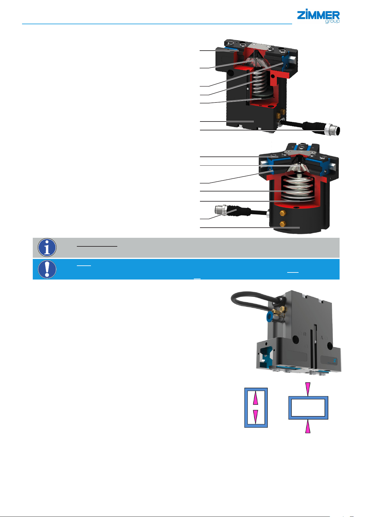
6.5 Inuencing the position sensor
In the adjacent gure, an area in which no magnets or components with
ferromagnetic properties may be fastened is marked.
This can have a signicant inuence on accuracy of the position sensor and/
or result in a malfunction of the position sensor.
NOTE:
The position sensor itself must never be covered up by fer-
romagnetic attachment or design elements.
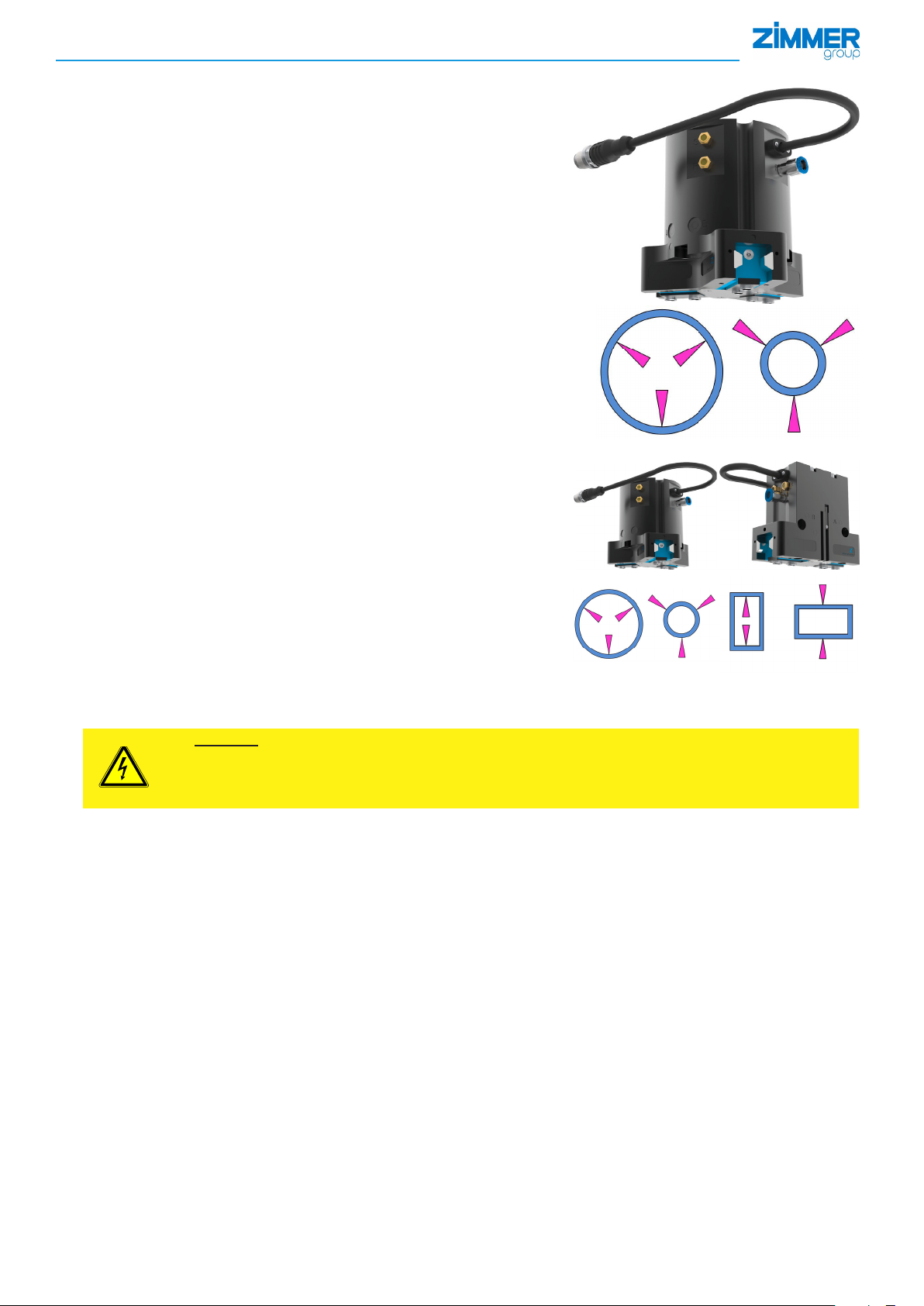
6.6 Pneumatic connection
7 Connection "R": Exhaust air with
mounted silencer
8 Connection "S": Exhaust air with
mounted silencer
9 Connection "P": Compressed air
8
9
7
INFORMATION:
The pneumatic connections A and B right on the gripper are not used and are closed.
For applications with an IP64 protection class, we recommend installing hoses on the "R" and "S" connections
for diverting the exhaust air to prevent the condensate from damaging the silencers.
7. Commissioning
7.1 IO-LINK commissioning
► Connecting the gripper to the IO-Link master
► Ensuring the supply voltage (for Port Class A additional supply via Y-cable)
8
7
9
Pin Color Function Explanation
1 Brown
2 White
3 Blue
4 Black
5 Gray
DDOC00247 enu / 2018-09-14 / Index a
Zimmer GmbH ● Im Salmenkopf 5 ● 77866 Rheinau, Germany ● Phone: +49 7844 9138-0
+24V DC sensor Power supply for IO-Link communication
+24V DC actuator Actuator supply voltage
GND sensor Sensor 0 V DC supply voltage
C/Q IO-Link communication
GND actuator Actuator 0 V DC supply voltage
●
Fax: +49 7844 9138-80 ● www.zimmer-group.de
6
Page 7
INSTALLATION AND OPERATING INSTRUCTIONS: Pneumatic gripper, intelligent GPP/GPD5000IL series
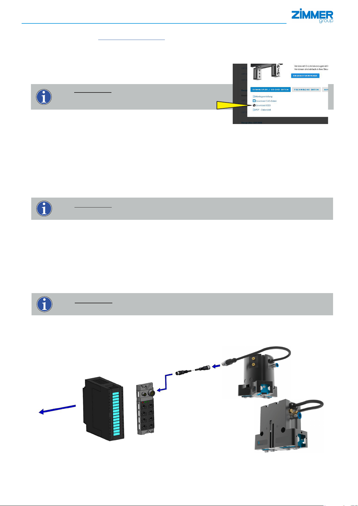
► Importing the IODD (device description) into the control system
Go the website https://ioddnder.io-link.com
Search for "Zimmer Group" in the search window that appears
Select the desired device and download the corresponding *.zip les
The complete content of the zip les is required for importing within the control
INFORMATION:
The IODD le can also be downloaded from
the product datasheet on our website.
Picture shown as example
When the hardware conguration is complete and the IO-Link connection to the gripper is established,
some data must already be visible in the process input data.
Some control systems demand a byte swap to bring this process data into a sequence that makes sense.
► To determine whether a byte swap is necessary, you can check Bit 6 [GripperPLCActive] in the "StatusWord".
► For this purpose, it is necessary to determine whether bit 6 [GripperPLCActive] is active in the rst or second status byte.
This bit must be the only one active in this byte.
If bit 6 in the rst byte is active, a byte swap still has to be applied here.
If bit 6 in the second byte is active, the bytes already have the correct sequence and you can continue with the rest of
the commissioning.
INFORMATION:
It is mandatory to carry out a verication of the process data
The gripper is controlled via IO-Link by means of the cyclical process data and the acyclical service data, with a cycle time of 5 ms.
During a communication cycle the IO-Link master sends 8 bytes to the gripper and receives 6 bytes of process data.
If the gripper is operational, a "1" must be sent in the "ControlWord" during a cold start for safety reasons. This "1" tells the gripper to
accept the current values that have been transmitted in the process data.
The gripper is now ready for operation. The gripper then moves to the proper position after receiving the corresponding command
in the "ControlWord" (decimal 256 or 512).
The gripper features bidirectional behavior. This means that the gripper cannot position itself on intermediate values. Each movement command is executed to the maximum possible position.
INFORMATION:
For more information, refer to the "StatusWord" section
7.2 Control
The gripper is controlled via IO-Link by means of the cyclical process data, with a minimum cycle time of 5 ms. During a communication cycle the IO-Link master sends 8 bytes to the gripper and receives 6 bytes of process data.
Fieldbus or PLC
DDOC00247 enu / 2018-09-14 / Index a
Zimmer GmbH ● Im Salmenkopf 5 ● 77866 Rheinau, Germany ● Phone: +49 7844 9138-0
IO-Link master
●
Fax: +49 7844 9138-80 ● www.zimmer-group.de
7
Page 8
INSTALLATION AND OPERATING INSTRUCTIONS: Pneumatic gripper, intelligent GPP/GPD5000IL series
The gripper is connected to the IO-Link master by a 5-pin M12 connector, in accordance with Port Class B. In doing so,
pin 1 (24 VDC) and pin 3 (0 VDC) are for supplying power.
Pin 2 (24 VDC) and pin 5 (0 VDC) are required for auxiliary power supply to the gripper.
Pin 4 is used for IO-Link communication between the gripper and the IO-Link master.
The actuator supply voltage acts on the internal valves. As a result of this voltage being switched-o, the valves will no longer be
able to be switched. In the event of an emergency (switch-o of the actuator voltage), the gripper bleeds the pistons and, depending
on the design of the gripper (N, NC, NO), there is no gripping force safety device present.
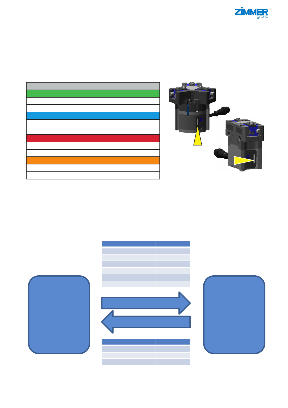
7.3 LED display
The color of the LED reects the status of the gripper.
Status Function
Green
On continuously Teach position
Flashing
Not currently assigned
Blue
On continuously Base position/Work position
Flashing
Not currently assigned
Red
On continuously The gripper has a fault
Flashing No IO-Link connection is available
Orange
On continuously Gripper is in undened position
Flashing
Not currently assigned
7.4. Process data
It is possible to control the gripper solely by the process data transmitted in each IO-Link cycle. To use this method of control,
a "0" must be continuously transmitted in the workpiece number.
As a result, the currently applied process data is used as a process parameter.
Unlike the gripping force and the "TeachPosition," the "ControlWord" and the "WorkpieceNo." are always valid!
If the gripper is controlled via the stored workpiece records, the values entered there are used as the current values. As a result, the
process data words "gripping force" and "TeachPosition" are devalued. The "WorkpieceNo." parameter is to be recognized as being
a selector switch.
Name Data type
ControlWord
DeviceMode.
WorkpieceNo.
TeachPosition
RESERVE
PositionTolerance
Outputs
UINT 16
UINT 8
UINT 8
UINT 16
UINT 8
UINT 8
GPP/GPD5000ILControl system
Inputs
DDOC00247 enu / 2018-09-14 / Index a
Zimmer GmbH ● Im Salmenkopf 5 ● 77866 Rheinau, Germany ● Phone: +49 7844 9138-0
Name Data type
Status
Diagnostics
ActualPosition
UINT 16
UINT 16
UINT 16
●
Fax: +49 7844 9138-80 ● www.zimmer-group.de
8
Page 9

INSTALLATION AND OPERATING INSTRUCTIONS: Pneumatic gripper, intelligent GPP/GPD5000IL series
7.5 Control with cyclical process data.
In general, the gripper can be controlled only by the cyclically exchanged process data.
However, this is possible only if a "0" is transmitted in the "WorkPosition" process data word.
Since very dierent gripper jaws exist for the gripper series, the required travel path can be determined directly with the gripper or
specially calculated by hand.
The process is as follows (gripping from the outside to the inside):
Step 1:
Insert the workpiece and set the "MoveToWork" bit (ControlWord = 512/0x200) by means of the "ControlWord" parameter.
This command makes the gripper move toward "WorkPosition" until it touches the workpiece.
Step 2:
If the gripper has been successfully stopped by the workpiece, then the corresponding travel path for this workpiece can be read
o using the actual position.
Step 3:
The travel path can be transferred to the gripper using the "TeachPosition." This allows the gripper to transmit feedback
about whether it has gripped the correct workpiece to the control system using the "Teach" bit in the "StatusWord"
(StatusWord = 512/0x0200). It may be necessary to adjust the position tolerance.
Step 4
To use this method, a "0" must be transmitted to the gripper in the WorkpieceNo." parameter.
Steps 1 and 2 can be repeated for as many workpieces as desired, and this allows dierent workpieces to be gripped securely
using the gripper.
The "StatusWord" parameter always tells the controller whether the gripper has gripped the workpiece.
INFORMATION:
The status of the gripper should be used to check whether a workpiece has been gripped correctly.
The position measurement resolution is 0.01 mm.
The position measurement accuracy is 0.01 mm.
If the "ActualPosition" parameter is used for detecting the workpiece, then uctuations around the exact value
must be taken into consideration during start-up.
7.5.1 Procedure for data transfer
All data that is transmitted to the gripper and is described in subsequent sections must be transmitted using the "handshake"
procedure.
INFORMATION:
This procedure is called "handshake" because it enables a "clean" transmission.
Data transmission takes place from "hand to hand" (between the control system and gripper).
"HANDSHAKE" procedure
The data transmission starts with the transmission of the
Subsequently, the response of the gripper must be tested using the
Data transmission is done by changing the corresponding process data and sending the "acquire" command by the
ControlWord = 0x01
The data transfer is completed with the
The gripper acknowledges this with
ControlWord = 0x00
ControlWord = 0x00
Status bit 12 = False
Status bit 12 = True
and the corresponding response from the gripper by
to the gripper.
.
.
the
"FAULT ACKNOWLEDGMENT" procedure
If the gripper has a fault, the error bit is set in the status word.
This fault can be reset by sending the
Status bit 12 = False
ControlWord = 0x8000
.
NOTE:
Not all faults can be reset. There are faults for which the error message is not reset after acknowledgment. The
user must wait until the gripper resets the fault by itself.
For example: Overtemperature fault case.
DDOC00247 enu / 2018-09-14 / Index a
Zimmer GmbH ● Im Salmenkopf 5 ● 77866 Rheinau, Germany ● Phone: +49 7844 9138-0
●
Fax: +49 7844 9138-80 ● www.zimmer-group.de
9
Page 10

INSTALLATION AND OPERATING INSTRUCTIONS: Pneumatic gripper, intelligent GPP/GPD5000IL series
Outputs: Process data from the IO-Link master to the GEP/GED5000IL
7.5.2 "ControlWord" parameter
Structure of the control word
Bit 15 Bit 14 Bit 13 Bit 12 Bit 11 Bit 10 Bit 9 Bit 8
Byte 1
Error
Reset
Bit 7 Bit 6 Bit 5 Bit 4 Bit 3 Bit 2 Bit 1 Bit 0
- - - - - "MoveToWork" "MoveToBase"
Byte 0
Note:
In the "ControlWord" parameter, only one single bit may be set at a time.
Only the values listed in the following table are valid.
Bit 0: "Datatransfer":
Setting this bit causes the gripper to take over the data transmitted in the process data ("WorkpieceNo." = 0) or the data
Bit 1: "WritePDU":
Setting this bit tells the gripper that it should write the current process data to the selected
workpiece recipe.
Bit 2: "ResetDirectionFlag":
Setting this bit tells the gripper that the direction ag needs to be reset. This makes it possible to repeatedly move to a
Adjust - - - Teach ResetDirectionFlag- WritePDU Data transfer
Decimal value Hexadecimal value
Data transfer
WritePDU
Teach
Adjust
MoveToWork
MoveToBase
Error Reset
stored in the workpiece data records ("WorkpieceNo." = 1 to 31) as the active data set.
position. This is useful when switching workpiece recipes.
1 0x1
2 0x2
8 0x8
128 0x80
256 0x100
512 0x200
32,768 0x8000
Bit 3: "Teach"
Setting this bit tells the gripper to save the current position as the "TeachPosition" in the selected "WorkpieceNo."
INFORMATION:
This only works if no "0" is transmitted in the workpiece No.!
Bit 7: "Adjust":
If no other bit is set in the control word, the "adjust" bit can be used to readjust the end position of the ngers. The "adjust"
bit has to be set briey. Afterwards, the gripper runs through an automated routine, which runs through a gripping cycle in
order to learn the end positions.
INFORMATION:
For more information on the dierent data sets of the "Adjust" parameter, refer to the "End positions" section.
Bit 8: "MoveToBase"
Setting this bit tells the gripper that it should move to the "BasePosition."
Bit 9: "MoveToWork"
Setting this bit tells the gripper that it should move to the "WorkPosition."
Bit 15: This bit can be used to acknowledge all errors that can be reset and thus reset them.
You can nd out whether an error is present from the error list.
DDOC00247 enu / 2018-09-14 / Index a
Zimmer GmbH ● Im Salmenkopf 5 ● 77866 Rheinau, Germany ● Phone: +49 7844 9138-0
●
Fax: +49 7844 9138-80 ● www.zimmer-group.de
10
Page 11

INSTALLATION AND OPERATING INSTRUCTIONS: Pneumatic gripper, intelligent GPP/GPD5000IL series
Details
Name ControlWord
Data type UINT 16
Permission Write
Transmission Cyclical
Value range 0–65535
7.5.3 "DeviceMode" parameter
This parameter is used to transmit the desired operating mode to the gripper.
Mode number Function
2 Switches valves o
100 Universal operation, internal and external gripping (N)
Details
Name DeviceMode
Data type UINT 8
Permission Write
Transmission Cyclical
Value range 0–255
INFORMATION:
All transmitted process data must be acquired using the "ControlWord" = 0x01 "Data transfer."
7.5.4 "WorkpieceNo." parameter
If a "0" is transmitted, the "TeachPosition" transmitted in the process data is considered valid for the gripper.
This parameter is used both for selecting the already stored workpiece data and for selecting the workpiece number record in order
to store it in the current process data.
Example: To use the data stored in workpiece record 3 ("PositionTolerance," "TeachPosition" and "DeviceMode"), a 3 (workpiece
number = 3) must be transmitted in the workpiece number of the process data.
Details
Name WorkpieceNo.
Data type UINT 8
Permission Write
Transmission Cyclical
Value range 0 - 32
INFORMATION:
For more information on the use of dierent data records of the parameter
"WorkpieceNo." refers to the "Work with workpiece numbers" section.
DDOC00247 enu / 2018-09-14 / Index a
Zimmer GmbH ● Im Salmenkopf 5 ● 77866 Rheinau, Germany ● Phone: +49 7844 9138-0
●
Fax: +49 7844 9138-80 ● www.zimmer-group.de
11
Page 12

INSTALLATION AND OPERATING INSTRUCTIONS: Pneumatic gripper, intelligent GPP/GPD5000IL series
7.5.5 "TeachPosition" parameter
The "TeachPosition" process data byte is only valid if, at the same time, the workpiece number is "0".
The "TeachPosition" tells the gripper the position at which the workpiece is expected. The "PositionTolerance" parameter can be
used to set a tolerance range around this position. Thus the gripper can distinguish whether a correct or incorrect workpiece has
been gripped. Conrmation that the correct workpiece has been gripped is communicated to the controller via the "StatusWord"
(input). If the detection is correct, the "teach" bit is set in this status word, thereby giving the user the option to monitor this work
step.
The stroke measurement system has a resolution of the position of 1/100 mm.
Product Stroke per gripper jaw Maximum "TeachPosition" (approx.)
GPP/GPD5006IL 6 mm 1200
GPP/GPD5008IL 8 mm 1600
GPP/GPD5010IL 10 mm 2000
Example: Explanation of the values using GPP5006IL
Full stroke of 6mm per gripper jaw:
"BasePosition" = 0
"WorkPosition" = 1200 (2*6*100 => 2 gripper jaws * 6 mm stroke per gripper jaw * Resolution at 1/100 mm)
The "TeachPosition" can acquire values from 0 to 1200
Details:
Name TeachPosition
Data type UINT 16
Permission Write
Transmission Cyclical
Value range 0–max. jaw stroke of the gripper
7.5.6. "PositionTolerance" parameter
This parameter can be used to transmit the current desired position detection tolerance for the workpiece to the gripper. Also see
Section 6.3.4
This can be input in mm/100 and always functions equally well in both the "+" direction and the "-" direction.
Details
Name Position tolerance
Data type UINT 8
Permission Write
Transmission Cyclical
Value range 0–255
INFORMATION:
All transmitted process data must be acquired using the "ControlWord" = 0x01 "Data transfer."
Refer to "HANDSHAKE" procedure
DDOC00247 enu / 2018-09-14 / Index a
Zimmer GmbH ● Im Salmenkopf 5 ● 77866 Rheinau, Germany ● Phone: +49 7844 9138-0
●
Fax: +49 7844 9138-80 ● www.zimmer-group.de
12
Page 13

INSTALLATION AND OPERATING INSTRUCTIONS: Pneumatic gripper, intelligent GPP/GPD5000IL series
Inputs: Process data from the IO-Link master to the GEP/GED5000IL
7.5.7. "StatusWord" parameter
Structure of the status word
Bit 15 Bit 14 Bit 13 Bit 12 Bit 11 Bit 10 Bit 9 Bit 8
Byte 1
Error
ControlWord
0x200
ControlWord
0x100
Data transfer
ok
undenedPosition WorkPosition TeachPosition BasePosition
Bit 7 Bit 6 Bit 5 Bit 4 Bit 3 Bit 2 Bit 1 Bit 0
Byte 0
Active
- - - - - -
GripperPLC
Bit 6: This bit is active as soon as the gripper has booted up after the cold start. This bit can be used to
verify a byte swap.
Bit 8: Active if the gripper is set to "BasePosition"
Bit 9: Active if the gripper is set to "TeachPosition"
Bit 10: Active if the gripper is set to "WorkPosition"
Bit 11: Active if the gripper is not set to any Teach Position
Bit 12: This bit is used for data transmission with the handshake.
This bit is active as soon as data has been taken over by the gripper by the parameter "ControlWord"=1 (DEZ)
Bit 13: This bit is a direction ag and is active when the last movement order was in the "BasePosition" direction
Bit 14: This bit is a direction ag and is active when the last movement order was in the "WorkPosition" direction
Bit 15: Error in the gripper. If this bit is active, the error message can be dened using the "Diagnostics" parameter.
INFORMATION:
For checking the correct gripping of the workpiece, the use of the "StatusWord" is
recommended.
The "TeachPosition" tolerance can be adjusted in another process parameter.
If the actual position is used to sense the correct position, the tolerances and uctuations of the value must be
observed during programming!
Details
Name StatusWord
Data type UINT 16
Permission Write
Transmission Cyclical
Value range 0–65535
7.5.8 "Diagnosis" parameter
The value returned in the "Diagnostics" parameter corresponds to the "Diagnostics code."
► refer to the "Error diagnostics" section
Details:
Name: Diagnostics
Data format: UINT16
Permission: Read
Transmission: Cyclical
Value range: 0 to 65535
DDOC00247 enu / 2018-09-14 / Index a
Zimmer GmbH ● Im Salmenkopf 5 ● 77866 Rheinau, Germany ● Phone: +49 7844 9138-0
●
Fax: +49 7844 9138-80 ● www.zimmer-group.de
13
Page 14

INSTALLATION AND OPERATING INSTRUCTIONS: Pneumatic gripper, intelligent GPP/GPD5000IL series
7.5.9 "ActualPosition" parameter
The "ActualPosition" parameter corresponds to the current position of the gripper jaws with respect to the full stroke of the gripper
and scaled to 0.01 mm.
Example: For a GPP5006IL gripper:
Depiction of the left gripper ngers:
Depiction of right gripper ngers:
Depiction of workpiece:
"Actual position" = "0" corresponds to the "Gripper to BasePosition" status (open): ...............
"Actual position" = "800" corresponds to the "Gripper to TeachPosition" status (workpiece gripped):
"Actual position" = "1200" corresponds to the "Gripper to WorkPosition" status (closed):
Details:
Name: ActualPosition
Data format: UINT16
Permission: Read
Transmission: Cyclical
Value range: 0 to max. jaw stroke of the gripper
7.6 Sensing of end positions
Two bits in the "status" parameter give feedback about the end positions.
The "BasePosition" bit (status = 768) is set when the base position is reached.
Accordingly, the "WorkPosition" bit (status = 1024) is set when the "WorkPosition" is reached.
The gripper is preset at the factory to have its end positions sensed at the maximum potential stroke of the gripper.
For special gripper jaws, if necessary, the end positions can be reset using an automated traversing routine. This means that the
"WorkPosition" or "BasePosition" will reference itself again accordingly.
► To this end, the "adjust" bit must be set in the "ControlWord" = 2048 for at least 2 seconds
The requirement here is that no additional bit is set in the "ControlWord"
If this bit is canceled before the end of the traversing routine, the procedure must be repeated because in this case the end
positions have not been correctly determined.
Warning:
At the gripper, a movement is triggered immediately when the bit is set!
► Risk of injury
► Before setting the bit, check whether the movement range of the gripper is clear.
7.7 Service parameters
Service data is not exchanged cyclically in each communication cycle. This data is exchanged only acyclically upon request of the
IO-Link master. Transmission of this acyclical data occurs over multiple communication cycles.
7.7.1 Status 0x40
This parameter can be used to read out the "StatusWord" of the gripper.
Details:
Name: StatusWord
Data format: UINT16
Permission: Read
Transmission: Acyclical
7.7.2 Diagnostics 0x41
This parameter can be used to read out the "DiagnosisWord" of the gripper.
Note: Corresponds to the process data eld
Details:
Name: Diagnostics
Data format: UINT16
Permission: Read
Transmission: Acyclical
DDOC00247 enu / 2018-09-14 / Index a
Zimmer GmbH ● Im Salmenkopf 5 ● 77866 Rheinau, Germany ● Phone: +49 7844 9138-0
●
Fax: +49 7844 9138-80 ● www.zimmer-group.de
14
Page 15

INSTALLATION AND OPERATING INSTRUCTIONS: Pneumatic gripper, intelligent GPP/GPD5000IL series
7.7.3 Cycle counter 0x42
This parameter can be used to read out the total number of cycles of the gripper.
During each gripping cycle, this parameter is incremented.
Details:
Name: Cycle counter
Data format: UINT32
Permission: Read
Transmission: Acyclical
7.7.4 System temperature 0x43
This parameter can be used to read out the current temperature of the electronics of the gripper.
Details:
Name: System temperature
Data format: INT16
Permission: Read
Transmission: Acyclical
7.7.5 ControlWord 0x44
This parameter can be used to read out the current ControlWord of the electronics of the gripper.
Details:
Name: ControlWord
Data format: UINT16
Permission: Read
Transmission: Acyclical
7.7.6 Error code 0x45
This parameter can be used to read out the fault status as a string.
Details:
Name: ErrorcodeDataformat STRING
Data format: UINT16
Permission: Read
Transmission: Acyclical
7.7.7 Error code 0x46
Returns the number of the faults that have occurred since the last restart.
Details:
Name: Error counter
Data format: UINT32
Permission: Read
Transmission: Acyclical
7.7.8 Operating seconds counter 0x47
This parameter can be used to read out the current operating time of the electronics of the gripper within seconds.
Details:
Name: Operating seconds counter
Data format: UINT32
Permission: Read
Transmission: Acyclical
DDOC00247 enu / 2018-09-14 / Index a
Zimmer GmbH ● Im Salmenkopf 5 ● 77866 Rheinau, Germany ● Phone: +49 7844 9138-0
●
Fax: +49 7844 9138-80 ● www.zimmer-group.de
15
Page 16

INSTALLATION AND OPERATING INSTRUCTIONS: Pneumatic gripper, intelligent GPP/GPD5000IL series
7.7.9 ActualPosition 0x100
The "ActualPosition" corresponds to the current position of the gripper jaws with respect to the full stroke of the gripper, scaled to
1/100 mm.
Details:
Name: ActualPosition
Data format: UINT16
Permission: Read
Transmission: Acyclical
Value range: 0–max. jaw stroke of the gripper
7.7.10 TeachPosition 0x101
This parameter can be used to read out the "TeachPosition" of the gripper that is currently being transmitted.
Details:
Name: TeachPosition
Data format: UINT16
Permission: Read
Transmission: Acyclical
7.7.11 WorkpieceNo. 0x102
This parameter can be used to read out the workpiece number of the gripper that is currently being transmitted.
Details:
Name: WorkpieceNo.
Data format: UINT8
Permission: Read
Transmission: Acyclical
7.7.12 DeviceMode 0x103
This parameter can be used to read out the driving mode of the gripper that is currently being transmitted.
Details:
Name: DeviceMode
Data format: UINT8
Permission: Read
Transmission: Acyclical
7.7.13 PositionTolerance 0x104
This parameter can be used to read out the tolerance of the "TeachPosition" of the gripper that is currently being transmitted.
Details:
Name: PositionTolerance
Data format: UINT8
Permission: Read
Transmission: Acyclical
7.7.14 Current operating pressure 0x110 -
This parameter can be used to read out the current operating pressure of the gripper. [in 1/10 bar]
Details:
Name: ActualPressure
Data format: UINT8
Permission: Read
Transmission: Acyclical
DDOC00247 enu / 2018-09-14 / Index a
Zimmer GmbH ● Im Salmenkopf 5 ● 77866 Rheinau, Germany ● Phone: +49 7844 9138-0
●
Fax: +49 7844 9138-80 ● www.zimmer-group.de
16
Page 17

INSTALLATION AND OPERATING INSTRUCTIONS: Pneumatic gripper, intelligent GPP/GPD5000IL series
7.7.15 Pressure switch bottom 0x111
This can be used to dene the minimum operating pressure (in increments of 0,1 bar) of the gripper, below which a diagnostic message is output.
Details:
Name: Low Pressure Error Threshold
Data format: UINT8
Permission: Read/write
Transmission: Acyclical
7.7.16 Pressure switch top 0x112
This can be used to dene the maximum operating pressure (in increments of 0,1 bar) of the gripper, above which a diagnostic
message is output.
Details:
Name: Pressure switch high
Data format: UINT16
Permission: Read
Transmission: Acyclical
7.7.17 Pressure hysteresis 0x113
This parameter can be used to specify the hysteresis-range of the pressure switch [in increments of 0,01 bar].
Details:
Name: PressureHysteresis
Data format: UINT8
Permission: Read/write
Transmission: Acyclical
7.7.18 Base/Work position switching thresholds 0x114
This parameter can be used to change the position switching thresholds for the Base- and WorkPosition.
Details:
Subindex 1: From the BasePosition to the outside
Subindex 2: From the BasePosition to the inside
Subindex 3: From the WorkPosition to the inside
Subindex 4: From the WorkPosition to the outside
Subindex 0: All 4 values at once
Name: Base/WorkPosition switching thresholds
Data format: UINT16 or UINT16[4]
Permission: Read/write
Transmission: Acyclical
7.7.19 Movement detection 0x115
With this, the threshold of the movement detection can be adjusted.
Details:
Name: Movement Threshold
Data format: UINT16
Permission: Read/write
Transmission: Acyclical
DDOC00247 enu / 2018-09-14 / Index a
Zimmer GmbH ● Im Salmenkopf 5 ● 77866 Rheinau, Germany ● Phone: +49 7844 9138-0
●
Fax: +49 7844 9138-80 ● www.zimmer-group.de
17
Page 18

INSTALLATION AND OPERATING INSTRUCTIONS: Pneumatic gripper, intelligent GPP/GPD5000IL series
8. Error diagnostics
Diagnostics
message
0x0 No error - -
0x100
0x101
0x102
The actuator power supply is not
available
Max. permitted temperature
exceeded
Temperature below min.
permitted temperature
0x104 Operating pressure too high
0x105 Operating pressure too low
0x300
0x301
0x304
0x305
0x306
0x307
The congured "ControlWord" is
implausible
The congured teach position is
outside the permitted range
The congured tolerance value
is outside the permitted range
The device has an incorrect
reference position
The congured "DeviceMode" is
not plausible
Movement order cannot be
carried out
0x308 "WorkpieceNo." not available
Error Possible causes Measures
• Actuator power supply not
connected
• Cable break
• Actuator power supply not
► Test of the actuator power supply
voltage
sucient
• Ambient temperature too high
• Gripper is overloaded
► Provide sucient ventilation/cooling
► Check the object to be gripped or the
gripper jaw
• Ambient temperature too low ► Provide a sucient operating
temperature
► Install the pressure control valve to
• Pressure in pressure supply set
too high
reduce the operating pressure
N: max. 8 bar
NC/NO: max. 7 bar
• Pressure supply not connected
• Line break
• Pressure in pressure supply set
► Check the pressure supply
(at least 2 bar)
too low
• Multiple bits are set in the
"ControlWord."
► Only one bit may be active on the
"ControlWord."
• Wrong value on the "TeachPosition" ► Test of the "TeachPosition"
parameters
Permissible range, depending on
design size.
Max. position value corresponds to
the back jaw stroke x 200
e.g.:
HRC with approx. 12 mm
Jaw stroke:
0 ≤ "TeachPosition" ≤ 1200
• Wrong value on the
"PositionTolerance" parameter
► Test of the "PositionTolerance"
parameters
Permitted range:
0 < "PositionTolerance" ≤ 255
• Gripper does not have any
reference position
• Wrong value on the "DeviceMode"
parameter
• Modied process data were not
taken over
Zimmer Group Service
► Adjusting the "DeviceModes"
Universal = 100
Grip workpiece outside = 60
Grip workpiece inside = 70
• Multiple move commands to the
same direction
• Move command transmitted
► Reset direction ag and resend move
command.
despite existing error
• Transmitted workpiece number is
outside the permitted range 0 to 32
• Modied process data were not
taken over
► Check the values of the
"WorkpieceNo." parameter
► Take over the process data with a
"Handshake"
DDOC00247 enu / 2018-09-14 / Index a
Zimmer GmbH ● Im Salmenkopf 5 ● 77866 Rheinau, Germany ● Phone: +49 7844 9138-0
●
Fax: +49 7844 9138-80 ● www.zimmer-group.de
18
Page 19

INSTALLATION AND OPERATING INSTRUCTIONS: Pneumatic gripper, intelligent GPP/GPD5000IL series
Diagnostics
message
Error Possible causes Measures
"TeachPosition" does not
0x309
correspond to the active value in
the gripper
Teach position tolerance does
0x30F
0x310
not correspond to the active
value in the gripper
"DeviceMode" sent by the
master does not correspond to
• Process data sent by the master
has been changed
the active value in the gripper
"WorkpieceNo." sent by the
0x311
master does not correspond to
the active value in the gripper
0x312
Initial status after a gripper
restart
• After a restart, a one-time data
takeover through "ControlWord"
= 1 must be carried out
0x404 Error of the position sensor
• Fault of the integrated position
sensor
0x406 System error • Internal system error
► Conrming the newly transmitted
process data with a "Handshake"
"ControlWord" = 0x1
► Conrming the current process data
with a "Handshake" "ControlWord" = 0x1
► Check whether the integrated position
sensor is influenced by an external
magnetic field
► Ensure the necessary distance between
the sensor and ferromagnetic materials
Zimmer Group Service
Zimmer Group Service
9. Accessories
If any accessories not sold or authorized by Zimmer Group are used, the function of the gripper cannot be guaranteed.
The accessory range of the Zimmer Group is specically tailored to and certied for the individual grippers.
Corresponding optional accessories or those included in the scope of supply can be found in the respective product data sheets at
www.zimmer-group.com.
DDOC00247 enu / 2018-09-14 / Index a
Zimmer GmbH ● Im Salmenkopf 5 ● 77866 Rheinau, Germany ● Phone: +49 7844 9138-0
●
Fax: +49 7844 9138-80 ● www.zimmer-group.de
19
Page 20

INSTALLATION AND OPERATING INSTRUCTIONS: Pneumatic gripper, intelligent GPP/GPD5000IL series
10. Glossary
Term/
abbreviation
"BasePosition"
"WorkPosition"
"TeachPosition"
"ActualPosition"
"ControlWord"
"DeviceMode"
"Workpiece No."
"PositionTolerance"
Base position
Initial position from which the gripper moves
Work position,
Any position of the gripper within the maximum and minimum possible movement range
Teach position,
for conditioning the gripper to the workpiece.
Current position,
Position of the gripper jaws with respect the maximum
possible stroke
Control word,
Parameter for command execution
Process parameter,
Switch that changes between movement proles of the gripper
Workpiece number,
Option for saving multiple recipes
Position tolerance,
referring to the tolerance of the teach position
Description
HRC
Human-Robot-Collaboration
Status Display parameter
Diagnostics
Diagnostics
Display parameter = error number
Oset Value for the subsequent correction of a parameter
"GripForce"
Direction
Gripping force
Value in the data set of the controller
Command/signal from the controller
Specication of the movement direction of the gripper jaws
Normal N The gripper can be used for both external and internal gripping (no gripping force safety device).
normally open
normally closed
NO The gripper is set up for external gripping.
With gripping force safety device
NC The gripper is set up for internal gripping.
With gripping force safety device
GND Ground/power supply 0V
Workpiece No.
Workpiece number
Designation of the data set in the control system
GPD Pneumatic gripper/three-jaw version
GPP Pneumatic gripper/two-parallel-jaw version
Traversing routine
Travel path
Adjust
DDOC00247 enu / 2018-09-14 / Index a
Zimmer GmbH ● Im Salmenkopf 5 ● 77866 Rheinau, Germany ● Phone: +49 7844 9138-0
Traversing routine
Dened process for moving the gripper jaws
Travel path
Path on which the gripper jaws travel
adjust
The gripper carries out an adjustment run
●
Fax: +49 7844 9138-80 ● www.zimmer-group.de
20
Page 21

INSTALLATION AND OPERATING INSTRUCTIONS: Pneumatic gripper, intelligent GPP/GPD5000IL series
11. Maintenance
INFORMATION:
B
value: 30.000.000 cycles.
10d
Maintenance-free operation of the gripper is guaranteed for up to 30 million gripping cycles.
The maintenance interval may shorten under the following circumstances:
Operation with compressed air that does not comply with DIN ISO 8573-1 quality class 4
Dirty environment
Improper use and use that does not comply with the performance data
Ambient temperature of more than 50°C; lubricants harden faster!
We recommend using the Zimmer GmbH repair service for maintenance and the replacement of seals.
Dismantling and reassembling the gripper without authorization may result in complications, as special installation equipment is
required in some cases.
12. Fault exclusion
► Inherently safe design engineering
The safety function is implemented using moving parts that are connected to each other through positive locking
No indirect triggering of the safety function caused by coupler elements (sensors, etc.)
► Proven technology
Methods in accordance with ISO 13949-1, Annex C, C.2 "Methods of good engineering practice"
MTTFd value = 150 years
Failure of the spring 4 "on the safe side" – No safety function failure
– Fatigue strength conrmed by the manufacturer
Failure of spring 4 – Fatigue strength conrmed by the manufacturer
Gate broken: Gripper jaw is no longer pulled inwards = force buildup no longer possible
► Wear resistance
Verication in above-mentioned endurance test that any potential wear does not impede the safety function
Use of wear-resistant materials for the safety-relevant components
Material of the gripper nger: 16MnCr5
DDOC00247 enu / 2018-09-14 / Index a
Zimmer GmbH ● Im Salmenkopf 5 ● 77866 Rheinau, Germany ● Phone: +49 7844 9138-0
●
Fax: +49 7844 9138-80 ● www.zimmer-group.de
21
Page 22

INSTALLATION AND OPERATING INSTRUCTIONS: Pneumatic gripper, intelligent GPP/GPD5000IL series
13. Declaration of incorporation
intermsoftheEUMachineryDirective2006/42/EC(AppendixII1B)
Name and address of the manufacturer:
Zimmer GmbH, Im Salmenkopf 5, D-77866 Rheinau, Germany, Phone: +49 7844 91380,
www.zimmer-group.de
We hereby declare that the incomplete machines described below
Product designation: Pneumaticparallelgripper/pneumaticthree-jawgripper
with intelligent control system
Type designation: GPP50��IL-/GPD50��IL-Series
conform to the requirements of the Machinery Directive, 2006/42/EC, Article 2g, Annex VII,b – Annex II,b, in their
design and the version we put on the market.
The following harmonized standards have been used:
• Basichealthandsafetyrequirements:No.1.1.2,No.1.1.3,No.1.1.5,No.1.3.1,No.1.3.2,No.1.3.4,No.1.3.7,No.1.5.1,
No.1.5.3,No.1.5.4,No.1.6.4,No.1.7.1,No.1.7.3.
• DINENISO12100:2011-03 Safetyofmachinery–Generalprinciplesfordesign–Riskassessment
and risk reduction
• DINEN60204-1 Safetyofmachinery–Electricalequipmentofmachines,part1
• DINENISO13849-1/-2 Safetyrelatedpartsofcontrolsystems
• DINENISO4414 Fluidpower–Generalrules–Safetyrequirementsforpneumaticsystems
and their components
Afulllistofappliedstandardsisavailableforviewingatthemanufacturer'sfacilities.
Commissioning of the incomplete machine is prohibited until it has been found that—where applicable—the
machine in which the above-mentioned incomplete machine is to be installed complies with the Machinery Directive
(2006/42/EC).
Authorized representative for compiling the
relevant technical documents
Kurt Ross Seemanufacturer'saddress Rheinau,Germany,2017-09-01 MartinZimmer
First name, last name Address (Placeanddateofissuance) (Legallybindingsignature)
ManagingPartner
DDOC00247 enu / 2018-09-14 / Index a
Zimmer GmbH ● Im Salmenkopf 5 ● 77866 Rheinau, Germany ● Phone: +49 7844 9138-0
●
Fax: +49 7844 9138-80 ● www.zimmer-group.de
22
Page 23

INSTALLATION AND OPERATING INSTRUCTIONS: Pneumatic gripper, intelligent GPP/GPD5000IL series
14. Declaration of conformity
intermsoftheEUDirective2014/30/EConelectromagneticcompatibility
Name and address of the manufacturer:
Zimmer GmbH, Im Salmenkopf 5, D-77866 Rheinau, Germany, Phone: +49 7844 91380,
www.zimmer-group.de
We hereby declare that the products described below
Product designation: Pneumaticparallelgripper/pneumaticthree-jawgripper
with intelligent control system
Type designation: GPP50��IL-/GPD50��IL-Series
conform to the requirements of the Electromagnetic Compatibility Directive 2014/30/EU in their design and the
version we put on the market.
The following harmonized standards have been used:
DINENISO12100:2011-03 Safetyofmachinery–Generalprinciplesfordesign–Riskassessmentand
risk reduction
DINEN61000-6-3 EMCGenericstandard,Emissionstandardforresidential,commercialandlight-industrial
environments
DINEN61000-6-2 EMCGenericstandard,Immunityforindustrialenvironments
DINEN61000-6-4 EMCGenericstandard,Emissionstandardforindustrialenvironments
Afulllistofappliedstandardsisavailableforviewingatthemanufacturer'sfacilities.
Authorized representative for compiling
the relevant technical documents
Kurt Ross Seemanufacturer'saddress Rheinau,Germany,2017-09-01 MartinZimmer
First name, last name Address (Placeanddateofissuance) (Legallybindingsignature)
ManagingPartner
DDOC00247 enu / 2018-09-14 / Index a
Zimmer GmbH ● Im Salmenkopf 5 ● 77866 Rheinau, Germany ● Phone: +49 7844 9138-0
●
Fax: +49 7844 9138-80 ● www.zimmer-group.de
23
Page 24

INSTALLATION AND OPERATING INSTRUCTIONS: Pneumatic gripper, intelligent GPP/GPD5000IL series
15. Your notes
DDOC00247 enu / 2018-09-14 / Index a
Zimmer GmbH ● Im Salmenkopf 5 ● 77866 Rheinau, Germany ● Phone: +49 7844 9138-0
●
Fax: +49 7844 9138-80 ● www.zimmer-group.de
24
 Loading...