

Zimmer GEP5006, GED5006, GEP5008, GED5008, GEP5010 Installation And Operating Instructions
...Page 1

INSTALLATION AND OPERATING
INSTRUCTIONS
Handling
Technology
GEP/GED5000 series
Electric gripper
THE KNOW-HOW FACTORY
Page 2
INSTALLATION AND OPERATING INSTRUCTIONS: ELECTRIC GRIPPER GEP/GED5000 SERIES
1. Supporting documents
Note:
The following documents are available for download on our website.
Only the documents currently available on the website are valid.
• Catalog
• Drawings, performance data, information about accessory parts, etc.
• General terms and conditions, including warranty information
2. Proper use
Note:
The gripper is to be used only in its original state with its original accessories, without any unauthorized
changes and within the scope of its dened parameters of use.
ZIMMER GmbH shall accept no liability for any damage caused by improper use.
The gripper is designed exclusively for electric operation using a supply voltage of 24 V DC.
The gripper is used as dened under "Proper use" in enclosed rooms to temporarily grip, handle and hold parts.
The gripper is not suitable for clamping workpieces during a machining process.
Direct contact with perishable goods/food is not permitted.
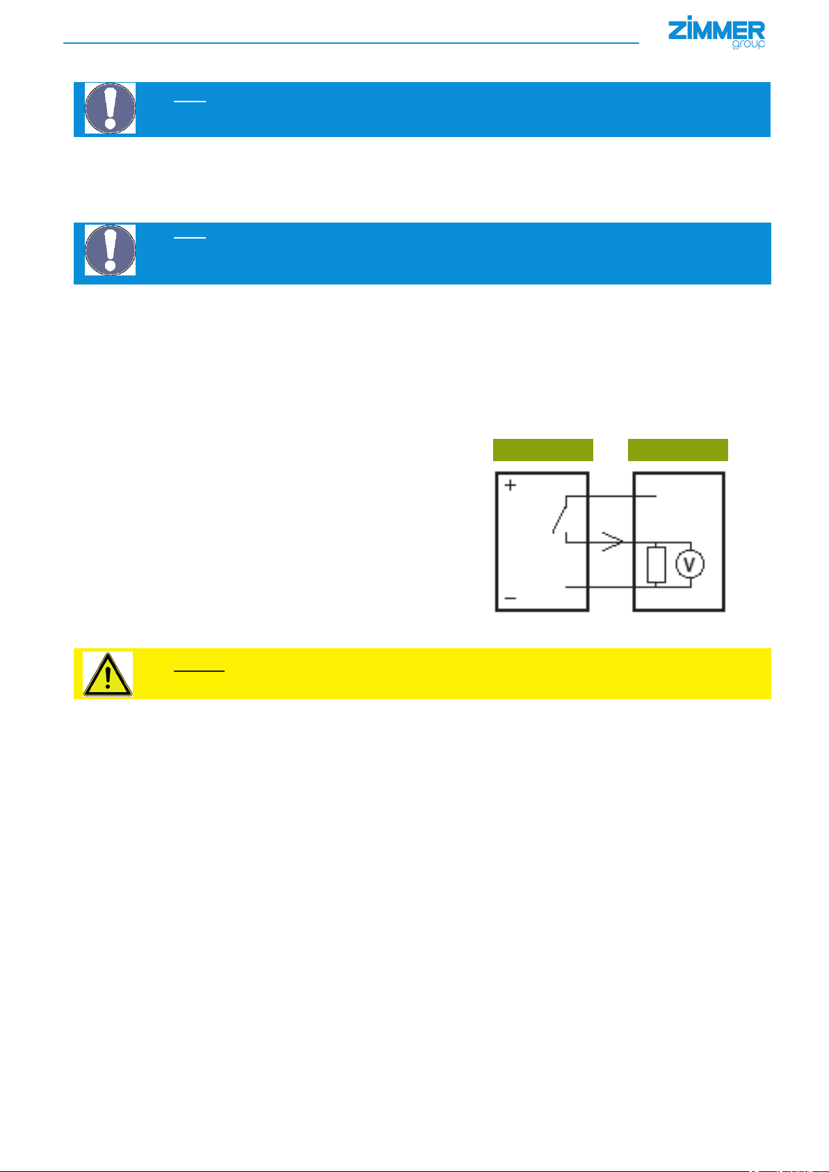
3. PNP switching logic used
If a sensor is connected to the input stage of a PLC, the input stage detects the state that the sensor is in (on or o). The prerequisite is that the PLC features the same switching logic as the sensor.
PNP sensor PNP input
When a PNP sensor is connected to a PNP input,
current ows from the sensor to the input. This means that a PNP input
must lower the current at the location where a PNP sensor draws current
Signal
Source current Sink current
Caution:
In the reverse case, an NPN sensor lowers current and an NPN input draws current.
EN/2015-10-07
DDOC00198/t
Zimmer GmbH ● Im Salmenkopf 5 ● 77866 Rheinau, Germany ● Phone: +49 7844 9138-0
●
Fax: +49 7844 9138-80 ● www.zimmer-group.de
2
Page 3
INSTALLATION AND OPERATING INSTRUCTIONS: ELECTRIC GRIPPER GEP/GED5000 SERIES
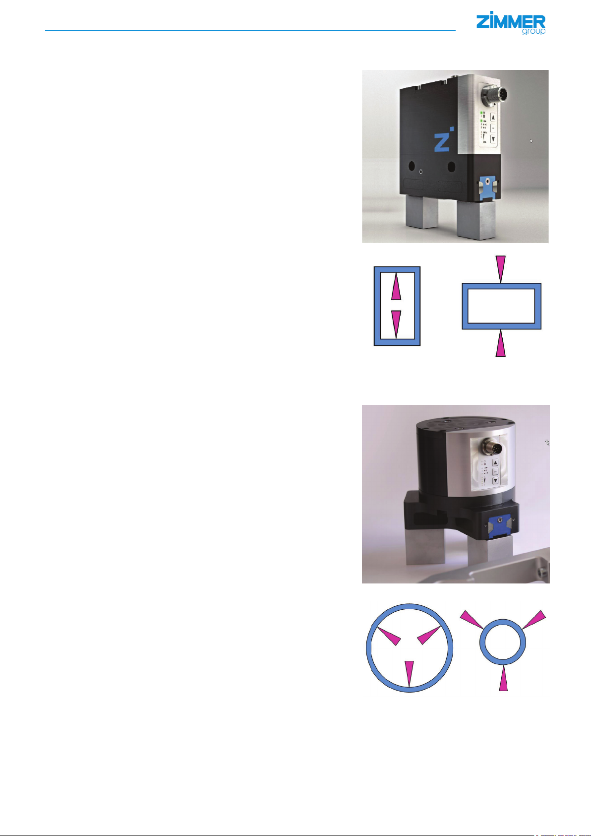
4. Function
4.1 GEP5000 function
The gripper ngers of the parallel gripper are arranged successively on two
shared guide rails and can be moved alongside each other.
A brushless DC motor* is used as the drive.
The rotational movement of the motor is converted into a linear movement using
a spindle drive to generate the opening and closing movement of the gripper.
The gripper is suitable for outward gripping. (NO = normally open) This means
the gripper moves at high speed back into the starting position
The gripper is suitable for inward gripping. (NC = normaly closed) This means
the gripper moves at high speed back into the starting position
4.2 GED5000 function
The gripper ngers of the three-jaw gripper are each positioned between two
steel guide rails.
A brushless DC motor* is used as the drive.
The rotational movement of the motor is converted into a linear movement using
a spindle drive to generate the opening and closing movement of the gripper.
The gripper is suitable for outward gripping. (NO = normally open) This means
the gripper moves at high speed back into the starting position
NCNO
The gripper is suitable for inward gripping. (NC = normally closed) This means
the gripper moves at high speed back into the starting position
EN/2015-10-07
*) See "Glossary" section for denitions
DDOC00198/t
Zimmer GmbH ● Im Salmenkopf 5 ● 77866 Rheinau, Germany ● Phone: +49 7844 9138-0
●
Fax: +49 7844 9138-80 ● www.zimmer-group.de
NCNO
3
Page 4

INSTALLATION AND OPERATING INSTRUCTIONS: ELECTRIC GRIPPER GEP/GED5000 SERIES
5. Personnel qualications
Installation, commissioning and operation may be undertaken by trained specialists only. They must have read and understood the
installation and operating instructions in full.
6. Installation
6.1 Safety notes
CAUTION:
Non-compliance may result in minor to serious injuries
Switch o the power supply for the electronics before any assembly, installation or maintenance work.
►
Risk of injury
NOTE:
Non-compliance may result in damage to the system
Switch o the power supply for the electronics before any assembly, installation or maintenance work.
►
6.2 Installing the gripper
The gripper can be installed from several sides on a mounting surface that meets the specications for evenness.
The following work steps are to be carried out to install the gripper:
► Insert centering sleeves into the provided matching parts on the gripper
► Position the gripper on the designated mounting surface using the centering sleeves
► Secure the gripper with cylinder screws of strength class 8.8
► Install the KAG1000B8 power supply cable (straight plug) or the KAW1000B8 power supply cable (angled plug)
Damage to the electronics possible
NOTE:
Non-compliance may result in damage to the system
For details on the tightening torque, screw diameter and maximum weight and length of the gripper ngers, refer
to the "Technical data" tables on the website www.zimmer-group-de.
Static charge
The seals move with the gripper jaws. This creates low voltages as a result of static charging. These charges cannot be
dissipated if the gripper is installed on an insulated surface,
nor can they be discharged through the workpiece.
NOTE:
Non-compliance may result in damage to the system
Grounding the gripper attachment/gripper jaws is recommended if ESD-sensitive parts* come into contact with
the gripper.
Heat dissipation
In the event of high ambient temperatures and a high clock frequency, the gripper has to be installed on heat-dissipating
materials.
EN/2015-10-07
*) See "Glossary" section for denitions
DDOC00198/t
Zimmer GmbH ● Im Salmenkopf 5 ● 77866 Rheinau, Germany ● Phone: +49 7844 9138-0
●
Fax: +49 7844 9138-80 ● www.zimmer-group.de
4
Page 5
INSTALLATION AND OPERATING INSTRUCTIONS: ELECTRIC GRIPPER GEP/GED5000 SERIES
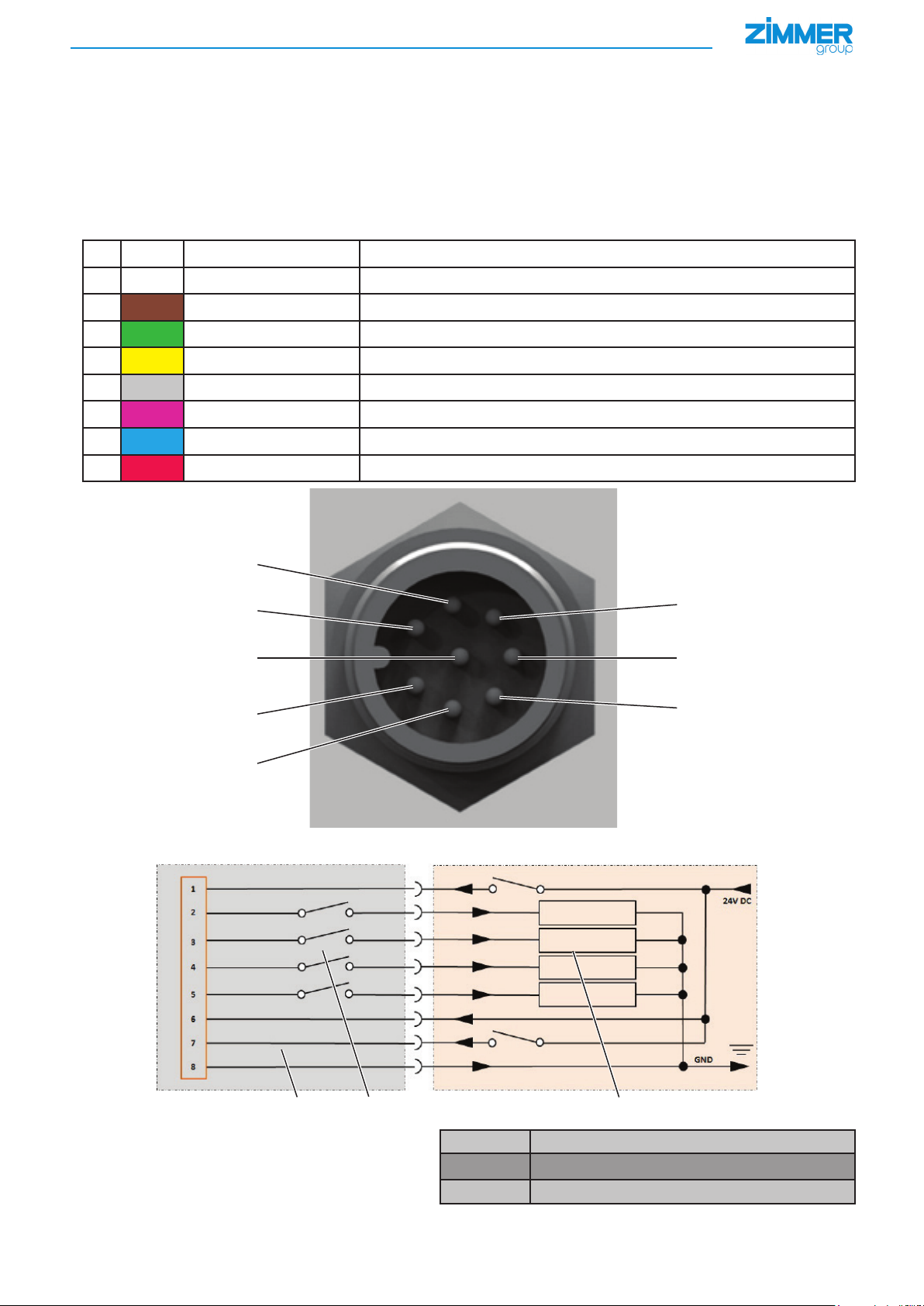
7. Commissioning
7.1 Control
To use the gripper, a voltage supply is required at pin 8 (0V) as well as at pin 6 (24 V DC/5 A).
Pin 1 serves as the control input used to open and close the gripper.
The signal of pin 1 must remain present until a counter movement of the gripper jaws is required.
The energy consumption during the movement of the gripper jaws is ≤ 5 A.
At resting position, the energy consumption of the gripper is < 150 mA.
The parameters can be set using the arrow keys on the membrane keyboard. (see section 7.3)
Cableconguration
Pin Color Function Explanation
1 White DIR* INPUT, open/close gripper control input, 24 V DC
2 Brown Work position OUTPUT, gripper in work position message
3 Green Error OUTPUT, error message
4 Yellow Teach position OUTPUT, gripper in programming position message
5
Gray Base position OUTPUT, gripper in programming position message
6 Pink +24 V DC +24 V DC/5A voltage supply
7 Blue Teach/adjust INPUT, control input, program/adjust workpiece
8 Red GND* Voltage supply 0V DC
7
1
8
2
3
6
5
4
Schematic view of controlling the GEP/GED 5000
10 11 12
EN/2015-10-07
*) See "Glossary" section for denitions
DDOC00198/t
Zimmer GmbH ● Im Salmenkopf 5 ● 77866 Rheinau, Germany ● Phone: +49 7844 9138-0
10
11
12
Gripper
Internal sensors, gripper position sensing
External control and programming unit
●
Fax: +49 7844 9138-80 ● www.zimmer-group.de
5
Page 6
INSTALLATION AND OPERATING INSTRUCTIONS: ELECTRIC GRIPPER GEP/GED5000 SERIES
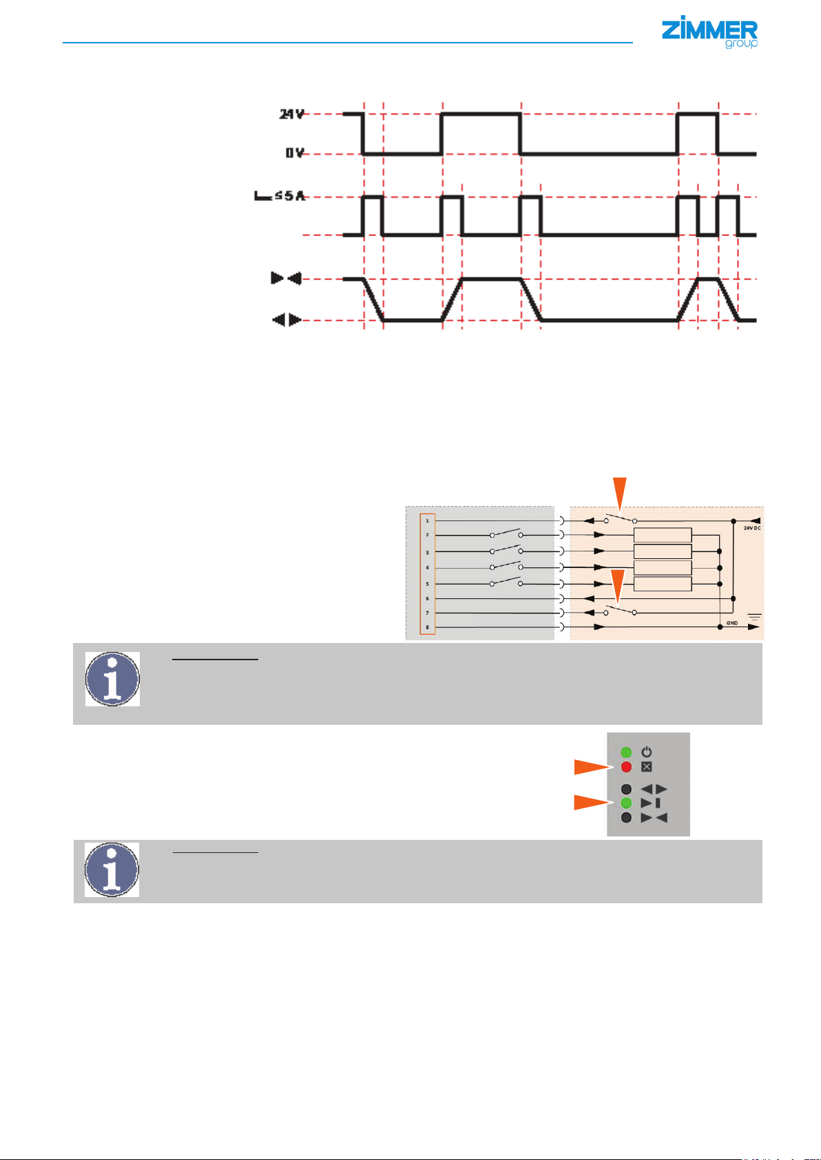
7.2 Switching sequence
Input 1 (DIR)
----------------------------------------------------------------------------------
Current draw
----------------------------------------------------------------------------------
Gripper position
-----------------------------------------------------------------------------------------------------------------------------------------------------------------------------------------------------------------------------------------------------
7.3 Intermediate position
• The intermediate position also called "workpiece gripped" can be programmed as desired.
• This requires moving the gripper jaws to the desired position (e.g. by gripping the workpiece).
• A signal (+24 V) is then applied to the pin 7 input (teach/adjust)* for a minimum of 0.5 seconds and a maximum of 3 seconds.
• Feedback is received via the pin 4 output (teached position)* in the process.
• The statuses are also shown on the gripper via the LED display.
Course of action for teaching the gripper with workpiece
1
► Put the gripper jaws into the desired position –
for instance by inserting a workpiece
► Close the gripper by applying a signal (+24V) at the PIN 1
(arrow 1) input
Error display lights up red (arrow A)
2
INFORMATION:
Important for handling the product.
The error message (A) appears because the gripper is not able to reach its end position as a result of the
inserted workpiece.
"The gripper is not yet aware that it has a workpiece between the gripper jaws."
► Apply a signal (+24 V) (arrow 2) on the pin 7 input (teach/
adjust*) for 0.5 to 3 seconds
The middle LED position display lights up green
(arrow B)
A
B
INFORMATION:
Important for handling the product.
"The gripper has learned where the workpiece is."
After the teach-in, the error message (arrow A) disappears during the next gripping movement.
EN/2015-10-07
*) See "Glossary" section for denitions
DDOC00198/t
Zimmer GmbH ● Im Salmenkopf 5 ● 77866 Rheinau, Germany ● Phone: +49 7844 9138-0
●
Fax: +49 7844 9138-80 ● www.zimmer-group.de
6
Page 7

INSTALLATION AND OPERATING INSTRUCTIONS: ELECTRIC GRIPPER GEP/GED5000 SERIES
7.4 End positions
End position conrmation occurs via pin 2 (work position)* and pin 5 (base position)*.
The statuses are visualized on the gripper via the LED display.
The gripper's end position sensing is preset by the plant.
If necessary, end positions can be re-set via an automatic traversing routine*.
► To do so, a signal (+24 V DC) must be applied to the pin 7 output (teach/adjust)* for at least 15 seconds.
A requirement is that the DIR signal is simultaneously set to "0".
► After approximately 3 seconds, the traversing routine* begins and is completed after 5 gripping cycles.
NOTE: Non-compliance may result in damage to the system
If the signal (+24 V DC) is interrupted before the end of the traversing routine, the procedure must be repeated
because the end positions are not correctly determined.
INFORMATION: Important for handling the product.
The setting of the intermediate position (Section 6.3) is lost when teaching-in the end positions!
After teaching-in the end positions, the intermediate position must be taught-in once again!
7.5 Minimum travel path
The gripper requires a minimum travel path of > 1,25 mm per jaw before it is permitted to reach a workpiece.
Failure to do so means the gripper cannot establish the desired gripping force and displays an error.
The minimum travel path applies to both movement directions and is independent of the gripper's starting position.
8. Operation
8.1 Control panel
The control panel of the gripper continuously displays the current status of the device and provides the option to modify various settings of the gripper using multiple menus
1 Power LED, power supply
2 Error LED, error display
3 Position display, menu display
4 Parameter display, binary error code display
5 Plus key, increase parameter value
6 Set button
7 Minus key, decrease parameter value
8.2 Position display
The positions of the gripper are displayed on the operator panel via three LEDs.
Gripper in base position
NC = gripper jaws open
NO = gripper jaws closed
Gripper is on a teached-in workpiece item
(teach-in position/teach position)
Base position Work position
Gripper is at the work position
(working position)
1
5
2
6
3
7
4
Teach position
If the gripper has been taught-in at an end posi-
tion, two LEDs are switched on simultaneously.
(Ex.: End position, work position and teach
position
EN/2015-10-07
*) See "Glossary" section for denitions
DDOC00198/t
Zimmer GmbH ● Im Salmenkopf 5 ● 77866 Rheinau, Germany ● Phone: +49 7844 9138-0
●
Fax: +49 7844 9138-80 ● www.zimmer-group.de
7
Page 8

INSTALLATION AND OPERATING INSTRUCTIONS: ELECTRIC GRIPPER GEP/GED5000 SERIES
8.3 Menu structure
Remaining operational life
Not assigned
"Position" teach area
"Gripper mode" menu
"Width" teach area
Remaining operational life
Based on 30 million cycles
Menu
Not assigned
Changing the
value
Value
Teach - Oset 1 - 5
Changing the
value
Value
Universal mode
NC, NO - operation
Changing the
value
Value
Window width 1 - 5
Changing the
value
Force setting
3 sec.
Main menu
3 sec.
8.4 Menu cycle course of action
► Call up the main menu by pressing SET (3 seconds)
The menu display LEDs will ash
► You can access the edit mode of a value by pressing SET once again
Parameter display LEDs will ash
Only possible in menus that feature a selection point
► A value can be changed in a range from 1 to 5 using the arrow keys
► Pressing SET saves the value and goes back to the menu display
These LEDs will now ash
► You can scroll through the menu items using the arrow keys
► You can only leave the menu by pressing SET in the main menu
No LED will ash
Value
Force mode 1 - 5
Display
Error diagnosis
EN/2015-10-07
INFORMATION: Important for handling the product.
If no input occurs after 3 minutes, the menu is left without saving the values.
*) See "Glossary" section for denitions
DDOC00198/t
Zimmer GmbH ● Im Salmenkopf 5 ● 77866 Rheinau, Germany ● Phone: +49 7844 9138-0
●
Fax: +49 7844 9138-80 ● www.zimmer-group.de
8
Page 9

INSTALLATION AND OPERATING INSTRUCTIONS: ELECTRIC GRIPPER GEP/GED5000 SERIES
8.5 Menu functions
Menu Designation Description
Menu 0
Main menu
Main menu
The error codes are also displayed here.
Refer to the "Error display diagnosis" section
Menu 1
Menu 2
Menu 3
Setting for the gripping force and travel speed in 5 steps
1= low gripping force/slow travel speed
Force setting
"Width" teach area
"Gripper mode" menu
If the gripping direction is dened, the corresponding gripper mode 2 or 3 shall be used.
The entire gripping cycle is sped up on the basis of the shorter return time of the gripper jaws.
As a result, the gripper is operated mechanically and electrically milder, to ensure a long operational life.
5= high gripping force/fast travel speed
(For details, refer to the "Technical data" section)
Default value: 4
Setting for the width in 5 steps
1 = small width
5 = large width
(For further details, see "Technical data" section)
Default value: 3
1 = universal operation in accordance with inward or outward gripping, both
movements with the same speed
2 = NC operation inward gripping with the desired force mode, quick outward
movement for reducing the cycle time
3 = NO operation outward gripping with the desired force mode, quick inward
movement for reducing the cycle time
Default value: 1
The gripper cannot drive to a permanent limit stop (such as a workpiece) during a fast backward movement, because it would be stressed beyond the permissible forces!
Menu 4
Menu 5
Menu 6
EN/2015-10-07
"Position" teach area
Menu not used
Remaining operational life
Oset for the teached-in position in 5 steps
1 = large oset in the direction of the base position
2 = small oset in the direction of the base position
3 = no oset
4 = small oset in the direction of the work position
5 = large oset in the direction of the work position
(For further details, see "Technical data" section)
Default value: 3
The parameter display LEDs show the remaining operational life of the gripper
relative to 30 million cycles.
5 = long remaining operational life
1 = short remaining operational life (less than 2 million cycles)
*) See "Glossary" section for denitions
DDOC00198/t
Zimmer GmbH ● Im Salmenkopf 5 ● 77866 Rheinau, Germany ● Phone: +49 7844 9138-0
●
Fax: +49 7844 9138-80 ● www.zimmer-group.de
9
Page 10

INSTALLATION AND OPERATING INSTRUCTIONS: ELECTRIC GRIPPER GEP/GED5000 SERIES
8.6 Menu settings
8.6.1 Menu 1: "Force settings"
INFORMATION:
For the technical data and gripping force charts, please visit our website:
www.zimmer-group.de
Should you have further questions about products or technical data, please contact ZIMMER GmbH Customer
Service. For this purpose, please call our technology hotline at +49 7844 9138-0.
8.6.2 Menu 2: "Width" teach area
Teach area Width [mm]
Teach area "width" [1] ≃ 0,2 mm
Teach area "width" [2] ≃ 0,4 mm
Teach area "width" [3] ≃ 0,6 mm
Teach area "width" [4] ≃ 1,2 mm
GEP5006/GED5006
Teach area "width" [5] ≃ 2,4 mm
Teach area Width [mm]
Teach area "width" [1] ≃ 0,2 mm
Teach area "width" [2] ≃ 0,4 mm
Teach area "width" [3] ≃ 0,6 mm
Teach area "width" [4] ≃ 1,2 mm
GEP5008/GED5008
Teach area "width" [5] ≃ 2,4 mm
Teach area Width [mm]
Teach area "width" [1] ≃ 0,2 mm
Teach area "width" [2] ≃ 0,4 mm
Teach area "width" [3] ≃ 0,6 mm
Teach area "width" [4] ≃ 1,2 mm
GEP5010/GED5010
Teach area "width" [5] ≃ 2,4 mm
EN/2015-10-07
DDOC00198/t
Zimmer GmbH ● Im Salmenkopf 5 ● 77866 Rheinau, Germany ● Phone: +49 7844 9138-0
●
Fax: +49 7844 9138-80 ● www.zimmer-group.de
10
Page 11

INSTALLATION AND OPERATING INSTRUCTIONS: ELECTRIC GRIPPER GEP/GED5000 SERIES
8.6.3 Menu 3: "Gripper mode"
N positioning mode
Force setting Value 1 Value 2 Value 3 Value 4 Value 5
Gripping force during closing [N] 540 620 710 860 960
Gripping force during opening [N] 540 620 710 860 960
Travel time during closing [s] 0,22 0,2 0,18 0,16 0,15
Travel time during opening [s] 0,22 0,2 0,18 0,16 0,15
Eective closing time [s] 0,255 0,235 0,215 0,195 0,185
Eective opening time [s] 0,255 0,235 0,215 0,195 0,185
GEP5006/GED5006
Max. length of gripper jaws [mm] 100 90 90 85 85
Response time [s] 0,035 0,035 0,035 0,035 0,035
NC positioning mode
Force setting Value 1 Value 2 Value 3 Value 4 Value 5
Gripping force during closing [N] 540 620 710 860 960
Gripping force during opening [N] - - - - -
Travel time during closing [s] 0,22 0,2 0,18 0,16 0,15
Travel time during opening [s] 0,13 0,13 0,13 0,13 0,13
Eective closing time [s] 0,255 0,235 0,215 0,195 0,165
Eective opening time [s] 0,165 0,165 0,165 0,165 0,165
GEP5006/GED5006
Max. length of gripper jaws [mm] 100 100 90 85 85
Response time [s] 0,035 0,035 0,035 0,035 0,035
NO positioning mode
Force setting Value 1 Value 2 Value 3 Value 4 Value 5
Gripping force during closing [N] - - - - -
Gripping force during opening [N] 540 620 710 860 960
Travel time during closing [s] 0,13 0,13 0,13 0,13 0,13
Travel time during opening [s] 0,22 0,2 0,18 0,16 0,15
Eective closing time [s] 0,165 0,165 0,165 0,165 0,165
Eective opening time [s] 0,255 0,235 0,215 0,195 0,185
GEP5006/GED5006
Max. length of gripper jaws [mm] 100 100 90 85 85
Response time [s] 0,035 0,035 0,035 0,035 0,035
EN/2015-10-07
DDOC00198/t
Zimmer GmbH ● Im Salmenkopf 5 ● 77866 Rheinau, Germany ● Phone: +49 7844 9138-0
●
Fax: +49 7844 9138-80 ● www.zimmer-group.de
11
Page 12

INSTALLATION AND OPERATING INSTRUCTIONS: ELECTRIC GRIPPER GEP/GED5000 SERIES
N positioning mode
Force setting Value 1 Value 2 Value 3 Value 4 Value 5
Gripping force during closing [N] 650 790 920 1090 1150
Gripping force during opening [N] 650 790 920 1090 1150
Travel time during closing [s] 0,29 0,27 0,25 0,22 0,18
Travel time during opening [s] 0,29 0,27 0,25 0,22 0,18
Eective closing time [s] 0,335 0,305 0,285 0,255 0,215
Eective opening time [s] 0,335 0,305 0,285 0,255 0,215
GEP5008/GED5008
Max. length of gripper jaws [mm] 125 115 115 105 105
Response time [s] 0,035 0,035 0,035 0,035 0,035
NC positioning mode
Force setting Value 1 Value 2 Value 3 Value 4 Value 5
Gripping force during closing [N] 650 790 920 1090 1150
Gripping force during opening [N] - - - - -
Travel time during closing [s] 0,29 0,27 0,25 0,22 0,18
Travel time during opening [s] 0,15 0,15 0,15 0,15 0,15
Eective closing time [s] 0,335 0,305 0,285 0,255 0,215
Eective opening time [s] 0,185 0,185 0,185 0,185 0,185
GEP5008/GED5008
Max. length of gripper jaws [mm] 125 115 115 105 105
Response time [s] 0,035 0,035 0,035 0,035 0,035
NO positioning mode
Force setting Value 1 Value 2 Value 3 Value 4 Value 5
Gripping force during closing [N] - - - - -
Gripping force during opening [N] 650 790 920 1090 1150
Travel time during closing [s] 0,15 0,15 0,15 0,15 0,15
Travel time during opening [s] 0,29 0,27 0,25 0,22 0,18
Eective closing time [s] 0,185 0,185 0,185 0,185 0,185
Eective opening time [s] 0,335 0,305 0,285 0,255 0,215
GEP5008/GED5008
Max. length of gripper jaws [mm] 125 115 115 105 105
Response time [s] 0,035 0,035 0,035 0,035 0,035
EN/2015-10-07
DDOC00198/t
Zimmer GmbH ● Im Salmenkopf 5 ● 77866 Rheinau, Germany ● Phone: +49 7844 9138-0
●
Fax: +49 7844 9138-80 ● www.zimmer-group.de
12
Page 13

INSTALLATION AND OPERATING INSTRUCTIONS: ELECTRIC GRIPPER GEP/GED5000 SERIES
N positioning mode
Force setting Value 1 Value 2 Value 3 Value 4 Value 5
Gripping force during closing [N] 980 1080 1200 1400 1520
Gripping force during opening [N] 980 1080 1200 1400 1520
Travel time during closing [s] 0,32 0,29 0,27 0,24 0,21
Travel time during opening [s] 0,32 0,29 0,27 0,24 0,21
Eective closing time [s] 0,335 0,325 0,305 0,275 0,245
Eective opening time [s] 0,345 0,325 0,295 0,275 0,245
GEP5010/GED5010
Max. length of gripper jaws [mm] 160 145 145 135 135
Response time [s] 0,035 0,035 0,035 0,035 0,035
NC positioning mode
Force setting Value 1 Value 2 Value 3 Value 4 Value 5
Gripping force during closing [N] 980 1080 1200 1400 1520
Gripping force during opening [N] - - - - -
Travel time during closing [s] 0,32 0,29 0,27 0,24 0,21
Travel time during opening [s] 0,16 0,16 0,16 0,16 0,16
Eective closing time [s] 0,345 0,325 0,295 0,275 0,245
Eective opening time [s] 0,2 0,2 0,2 0,2 0,2
GEP5010/GED5010
Max. length of gripper jaws [mm] 160 145 145 135 135
Response time [s] 0,035 0,035 0,035 0,035 0,035
NO positioning mode
Force setting Value 1 Value 2 Value 3 Value 4 Value 5
Gripping force during closing [N] - - - - -
Gripping force during opening [N] 980 1080 1200 1400 1520
Travel time during closing [s] 0,16 0,16 0,16 0,16 0,16
Travel time during opening [s] 0,32 0,29 0,27 0,24 0,21
Eective closing time [s] 0,2 0,2 0,2 0,2 0,2
Eective opening time [s] 0,345 0,325 0,295 0,275 0,245
GEP5010/GED5010
Max. length of gripper jaws [mm] 160 145 145 135 135
Response time [s] 0,035 0,035 0,035 0,035 0,035
EN/2015-10-07
DDOC00198/t
Zimmer GmbH ● Im Salmenkopf 5 ● 77866 Rheinau, Germany ● Phone: +49 7844 9138-0
●
Fax: +49 7844 9138-80 ● www.zimmer-group.de
13
Page 14

INSTALLATION AND OPERATING INSTRUCTIONS: ELECTRIC GRIPPER GEP/GED5000 SERIES
8.6.4 Menu 4: "Position" teach area
"Position" teach area Oset[mm]
Teach area "oset" [1] ≃ - 0,8 mm
Teach area "oset" [2] ≃ - 0,4 mm
Teach area "oset" [3] ≃ 0 mm
Teach area "oset" [4] ≃ + 0,4 mm
GEP5006/GED5006
Teach area "oset" [5] ≃ + 0,8 mm
"Position" teach area Oset[mm]
Teach area "oset" [1] ≃ - 0,8 mm
Teach area "oset" [2] ≃ - 0,4 mm
Teach area "oset" [3] ≃ 0 mm
Teach area "oset" [4] ≃ + 0,4 mm
GEP5008/GED5008
Teach area "oset" [5] ≃ + 0,8 mm
"Position" teach area Oset[mm]
Teach area "oset" [1] ≃ - 0,8 mm
Teach area "oset" [2] ≃ - 0,4 mm
Teach area "oset" [3] ≃ 0 mm
Teach area "oset" [4] ≃ + 0,4 mm
GEP5010/GED5010
Teach area "oset" [5] ≃ + 0,8 mm
EN/2015-10-07
DDOC00198/t
Zimmer GmbH ● Im Salmenkopf 5 ● 77866 Rheinau, Germany ● Phone: +49 7844 9138-0
●
Fax: +49 7844 9138-80 ● www.zimmer-group.de
14
Page 15

INSTALLATION AND OPERATING INSTRUCTIONS: ELECTRIC GRIPPER GEP/GED5000 SERIES
9. Maintenance
9.1 Maintenance intervals
The gripper does not require maintenance.
The operational life of up to 30 million cycles may become reduced under the following circumstances:
• Dirty environment
• Improper use
• Unapproved performance data and parameters for use
• Use of sealing air
9.2 Disassembling the gripper
We recommend using the Zimmer Group Repair Service for repairs.
Unauthorized dismantling and reassembly of the gripper can result in complications as in some cases, special mounting equipment
is required. In addition, the warranty is void if the gripper is opened.
10. Remedy
10.1 Error diagnosis
The red error LED indicates that an error has occurred. The main menu must be selected to see the error code. The ve lower LEDs
represent the current error code in binary form.
In the following example, error code 7 is active:
The error is acknowledged via a new DIR signal.
1 "Error" LED display
2 Position display
3 Error code display
1
2
3
10.2 Display troubleshooting
Error code Error Possible cause •Measure
0
1
2
3
No error
Motor has slight overcurrent in
several consecutively following
cycles
Motor has strong excess
current
Motor has excess current in
idle mode
• Gripper is dicult to move
• Travel path of the gripper is
impeded
• Object being gripped or gripper
• Check the gripper's freedom of
movement
• Check the object being gripped
and gripper jaws
jaws are elastic
• Gripper is blocked
• Internal error
• Restore the free movement of the
gripper once again
• Zimmer Group Service
• Internal error • Zimmer Group Service
4
Motor output stage
temperature above the limit
value
EN/2015-10-07
*) See "Glossary" section for denitions
DDOC00198/t
Zimmer GmbH ● Im Salmenkopf 5 ● 77866 Rheinau, Germany ● Phone: +49 7844 9138-0
• Ambient temperature too high
• Gripper is overloaded
●
Fax: +49 7844 9138-80 ● www.zimmer-group.de
• Provide sucient ventilation/
cooling
• Check the object to be gripped or
the gripper jaw
15
Page 16

INSTALLATION AND OPERATING INSTRUCTIONS: ELECTRIC GRIPPER GEP/GED5000 SERIES
5
6
7
8
9
Gripper is in reference run
mode
Gripper has no reference on
the jaw position
Motor is in setting drive mode
at the end positions
(see Section 6.4)
Gripper did not reach the end
position (base, teach-in or work
position)
Gripper does not reach the
target speed
• Internal error • Zimmer Group Service
• Gripper has lost its reference
position
• Setting drive has been started
(Caution: During the setting run,
positions are not evaluated)
• The gripper does not reach its work,
base or teach-in position
• Diculty moving the guide • Zimmer Group Service
• Zimmer Group Service
• Wait for completion of the
adjustment procedure
• Check the object being gripped
or the gripper jaws
10
11
12
13
14
The "jaw position" sensor has
an error
The temperature sensor has
an error
The gripper has a general
system error
DIR signal = 0, but the gripper
does not reach the base
position or the teach-in position
DIR signal = 1, but the gripper
does not reach the work
position or the teach-in position
• Internal error • Zimmer Group Service
• Internal error • Zimmer Group Service
• Internal error • Zimmer Group Service
• Gripper is blocked
• Diculty moving the guide
• Gripper is blocked
• Diculty moving the guide
• Restore the ease of movement of
the gripper
• Zimmer Group Service
• Restore the ease of movement of
the gripper
• Zimmer Group Service
15
EN/2015-10-07
*) See "Glossary" section for denitions
DDOC00198/t
Zimmer GmbH ● Im Salmenkopf 5 ● 77866 Rheinau, Germany ● Phone: +49 7844 9138-0
Gripper is blocked • Gripper is dicult to move
• Travel path of the gripper is
impeded
●
• Restore the ease of movement of
the gripper
Fax: +49 7844 9138-80 ● www.zimmer-group.de
16
Page 17

INSTALLATION AND OPERATING INSTRUCTIONS: ELECTRIC GRIPPER GEP/GED5000 SERIES
16
17
18
The gripper has exceeded the
maximum travel time
Gripper does not reach
the target speed when
approaching
Gripper is in NC or NO mode
and is blocked from free run
(see Section 7.5, menu 3 menu
function)
• Gripper is dicult to move
• Travel path of the gripper is impeded
• Diculty moving the guide • Zimmer Group Service
• Gripper is dicult to move
• In its fast backward movement, the
gripper moves to a xed stop (i.e.
object being gripped)
• Restore the ease of movement of
the gripper
• Change gripper mode
• Zimmer Group Service
INFORMATION:
Important for handling the product.
Errors remain active until a switchover of the DIR signal or a zero crossing of the grippers' voltage supply. An
error can therefore be acknowledged with a switchover of the DIR signal.
EN/2015-10-07
*) See "Glossary" section for denitions
DDOC00198/t
Zimmer GmbH ● Im Salmenkopf 5 ● 77866 Rheinau, Germany ● Phone: +49 7844 9138-0
●
Fax: +49 7844 9138-80 ● www.zimmer-group.de
17
Page 18

INSTALLATION AND OPERATING INSTRUCTIONS: ELECTRIC GRIPPER GEP/GED5000 SERIES
11. Declaration of Incorporation
in the context of EU Machinery Directive 2006/42/EC (Annex II 1 B)
Name and address of the manufacturer:
ZIMMER GmbH, Im Salmenkopf 5, D-77866 Rheinau, Germany, Phone: +49 7844 91380,
www.zimmer-group.de
We hereby declare that the incomplete machines described below
Product designation: Electric parallel gripper, electric three-jaw gripper
Type designation: GEP5
���-/GED5���-Series
conform to the requirements of the Machinery Directive, 2006/42/EC, Article 2g, Annex VII,b – Annex II,b, in their
design and the version we put on the market.
The following harmonized standards have been used:
• Basic health and safety requirements: No. 1.1.2, No. 1.1.3, No. 1.1.5, No. 1.3.1, No. 1.3.2, No. 1.3.4, No. 1.3.7, No. 1.5.1,
No. 1.5.3, No. 1.5.4, No. 1.6.4, No. 1.7.1, No. 1.7.3.
•DIN EN ISO 12100:2011-03 Safety of machinery – General principles for design - Risk assessment and risk reduction
•DIN EN 60204-1 Safety of machinery – Electrical equipment of machines, part 1
•DIN EN ISO 13849-1 Safety function for superimposed hazards
•DIN EN ISO 13849-2 Safety related parts of control system
A full list of applied standards can be obtained from the manufacturer.
Commissioning of the incomplete machine is prohibited until it has been found that—where applicable—the
machine in which the above-mentioned incomplete machine is to be installed complies with the Machinery Directive
(2006/42/EC).
Authorized representative for compiling the
relevant technical documents
Kurt Ross See manufacturer's address Rheinau, Germany, 2013-11-21 Martin Zimmer
First name, last name Address (Place and date of issuance) (Legally binding signature)
Managing Partner
12. Declaration of Conformity
in the context of EC Directive 2014/30/EC on electromagnetic compatibility
Name and address of the manufacturer:
ZIMMER GmbH, Im Salmenkopf 5, D-77866 Rheinau, Germany, Phone: +49 7844 91380,
www.zimmer-group.de
We hereby declare that the products described below
Product designation: Electric gripper
Type designation: GEP5
���-/GED5���-Series
conform to the requirements of the Electromagnetic Compatibility Directive 2014/30/EU in their design and the
version we put on the market.
The following harmonized standards have been used:
DIN EN ISO 12100:2011-03 Safety of machinery - General principles for design - Risk assessment and risk reduction
DIN EN 61000-6-3 EMC Generic standard, Emission standard for residential, commercial and light-industrial
environments
DIN EN 61000-6-2 EMC Generic standard, Immunity for industrial environments
DIN EN 61000-6-4 EMC Generic standard, Emission standard for industrial environments
A full list of applied standards can be obtained from the manufacturer.
Authorized representative for compiling the
relevant technical documents
EN/2015-10-07
Kurt Ross See manufacturer's address Rheinau, Germany, 2013-11-21 Martin Zimmer
First name, last name Address (Place and date of issuance) (Legally binding signature)
Managing Partner
DDOC00198/t
Zimmer GmbH ● Im Salmenkopf 5 ● 77866 Rheinau, Germany ● Phone: +49 7844 9138-0
●
Fax: +49 7844 9138-80 ● www.zimmer-group.de
18
Page 19

INSTALLATION AND OPERATING INSTRUCTIONS: ELECTRIC GRIPPER GEP/GED5000 SERIES
13. Accessories/scope of delivery
If any accessories not sold or authorized by Zimmer Group are used, the function of the gripper cannot be guaranteed. Zimmer
Group's range of accessories is specially tailored to the individual grippers.
Corresponding optional accessories and those included in the scope of supply can be found at www.zimmer-group.com.
14. Glossary
AC motor Motor run on AC power
Adjust Congure
Base position Base position of the gripper
DC motor Motor run on DC power
DIR Direction/24 V supply line
Error Fault, error message
ESD Electrostatic discharge, electrostatic sensitivity
GED Gripper/electrically powered/three-jaw design
GEP Gripper/electrically powered/2 parallel jaws
GND Abbreviation for "Ground" – ground connection
LED Light-emitting diode
NO "Normally Open" gripper mode – inward gripping - the gripper is open when not activated
NC "Normally Closed" gripper mode – outward gripping - the gripper is closed when not activated
Oset Correction value
Teach position Programming/teaching the gripper to the position of the workpiece
Work-Position Work position of the gripper
VAC Volts in AC current
VDC Volts in DC current
Traversing routine Dened process for the movement of the clamping jaws
Travel path Path on which the gripper jaws return
EN/2015-10-07
DDOC00198/t
Zimmer GmbH ● Im Salmenkopf 5 ● 77866 Rheinau, Germany ● Phone: +49 7844 9138-0
●
Fax: +49 7844 9138-80 ● www.zimmer-group.de
19
 Loading...